
Related Manuals for Carrier 09VE


Summary of Contents for Carrier 09VE
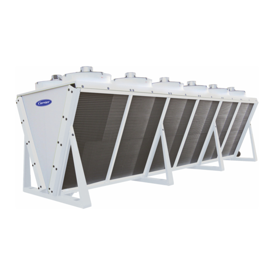
- Page 1 O P E R AT I O N A N D M A I N T E N A N C E I N S T R U C T I O N S DRYCOOLER 09VE Translation of the original document...
-
Page 3: Table Of Contents
CONTENTS 1 - RECEIVING THE UNIT .................................. 4 1.1 - General checks ..................................4 1.2 - Unloading ....................................4 2 - SAFETY INSTRUCTIONS ................................4 2.1 - In an emergency..................................4 2.2 - The 4 main risks ..................................4 3 - GENERAL INFORMATION ................................5 3.1 - Unit functions..................................... -
Page 4: Receiving The Unit
■ After unpacking the unit, please inspect it for any damage. ■ If any items are missing or in case of damage, specify this on the delivery slip and inform the carrier by registered letter within 3 days of delivery of the unit. 1.2 - Unloading ■... -
Page 5: General Information
3 - GENERAL INFORMATION 3.1 - Unit functions ■ Drycooler: Device in which a fluid in liquid state is cooled by heat exchange with the ambient air, without direct contact between the ambient air and the fluid. ■ Misting option: System for cooling air by misting of water droplets under high pressure. ■ These devices must only be used for the purpose for which they are intended. In particular, it is formally prohibited to use any fluid other than that specified in the order documents. 3.2 - Standards ■ Every unit meets standards EN 60-204 as well as the following European directives: - Machinery 2006/42/EU - EMC 2014/30/EU - PED 2014/68/EU ■ Technicians who install, commission, operate and service the unit must understand the instructions given in this manual and be familiar with the specific technical characteristics of the installation site. -
Page 6: Instructions For Lifting And Transportation
5 - INSTRUCTIONS FOR LIFTING AND TRANSPORTATION ■ The weights are given on the data plates. ■ To lift the units, it is essential to refer to the yellow lifting labels affixed to the unit and fix the slings to the slinging points shown on these The lifting mode is shown on the dimensional drawing supplied with the order. 5.1 - Handling units using rings fixed to the roof: standard units Standard units from 6 to 16 FMAs Yellow "Lifting instructions"... -
Page 7: Handling Units Using Sling Stops Fixed Underneath: Special Units
5 - INSTRUCTIONS FOR LIFTING AND TRANSPORTATION 5.2 - Handling units using sling stops fixed underneath: special units e.g.: C5M, copper fins, STAINLESS STEEL pipe wiring bundles, ATEX, STAINLESS STEEL casing. Textile slings only Slings Yellow "Lifting instructions" sticker Sling stop 3390 4540 5690 6840 4600 4600 6900 6900 4100 4100 5000 6000 4100 4000 6100 6100... -
Page 8: Location
7 - LOCATION ■ For structures with a "special" seismic risk, please consult us. ■ Before setting up the unit in its intended location, the installer must check the following points: - The unit must be installed outdoors in an area protected from flooding. Ensure that all conditions have been taken into account (negative outdoor temperatures, corrosive atmosphere, altitude, etc.) - The ground surface or structure must be level and strong enough to bear the unit's weight. - Raise the unit if it is installed in a snowy area, in order to ensure a sufficient air intake height. -
Page 9: Installation Recommendations
8 - INSTALLATION RECOMMENDATIONS ■ Ensure sufficient devices are provided to guarantee the protection of persons and property, and to enable maintenance operations to be carried out in complete safety. ■ If a malfunction would have significant human, environmental or financial consequences, take appropriate steps to limit the effects. ■ Ensure that the installation complies with the legal texts and codes in force in the country of operation, and that it complies with the safety rules applicable to the site where it is being used (explosive atmosphere, for example). ■ If necessary, affix to the machine the hazard symbol corresponding to the fluid in accordance with current standards. ■ Install burn hazard signs wherever the internal temperature of pipes exceeds 65°C. ■ Fit safety devices to prevent the fluid temperature or pressure from exceeding the values indicated in the order. Approval for operation at higher conditions must be obtained from us. ■ The unit must be fitted with an immediately accessible emergency stop device; this visible device must allow the electrical supply to the unit and its accessories to be cut completely. ■... -
Page 10: Connections
9 - CONNECTIONS 9.1 - Electrical connection ■ All wiring must be connected in accordance with the regulations that apply to the installation site (e.g. NF C 15100 in France). ■ In all cases, refer to the "ELECTRICAL CONNECTION" document or wiring diagram attached to the unit. ■... -
Page 11: Operation
10 - OPERATION 10.1 - First commissioning ■ Read the guides for commissioning any accessories very carefully and follow all advice. ■ Check that the supply voltage corresponds to that given on the data plate. ■ Retighten the connections of the electrics box. ■ Switch the unit on and check that all the fans are turning in the correct direction (direction of rotation shown on the labels). In the event of abnormal noise coming from the fan motor assemblies, immediately switch off the power supply and contact us. -
Page 12: Ac Fan Motor Assemblies
11 - AC FAN MOTOR ASSEMBLIES 11.1 - AC motor protection ■ All the motors are equipped with a thermal cut-out, which is available in the motor terminal box. Wiring for the thermal cut-out is optional 11.2 - Fan with AC motor (3-ph 230 V/400 V 50 Hz) ■ On a 3-ph/400 V/50 Hz network, the motors have 2 rotation speeds, via star (Y) or delta connection (Δ). - Low speed with Y connection - High speed with Δ connection ■ On a 3-ph/230 V/50 Hz electrical network, the motors have 1 rotation speed via delta connection (Δ): - Low speed with Δ connection Impeller diameter Motor type 3-PH/230 V supply... -
Page 13: Ec Fan Motor Assemblies
12 - EC FAN MOTOR ASSEMBLIES 12.1 - EC motor protection ■ These motors feature integrated protection and monitoring devices. They are protected against thermal overload of the electronic components and motors, and against any failure of the Hall effect sensors to analyse the position of the rotor. ■... -
Page 14: Maintenance
13 - MAINTENANCE 13.1 - Recommendations for maintenance ■ Make sure power to the unit has been disconnected before servicing. ■ Reduce the temperature and pressure before carrying out any work on the bundle. ■ Do not make any modifications without our agreement. ■ Do not walk directly on the unit. ■... -
Page 15: Removing And Refitting A Fan
13 - MAINTENANCE 13.4 - Removing and refitting a fan ■ The removal of a fan is a simple operation, however special care must be taken during handling, in particular: - Do not pull on the blades. - Place the fan motor assembly on a safe surface away from areas of activity. - If the unit is to be shipped, provide the necessary protection and packing materials. - Do not remove the panel. - Page 16 13 - MAINTENANCE ■ To refit, position the fan on the 12 unit inserts and carry out the operations in the reverse order to removal, using only the bolts provided: - M8x25 bolts and flat washer for V units (tightening torque 12 Nm). - M10x25 bolts for flatbed units (tightening torque 24 Nm). M8x25 bolts and flat washer M10x25 bolts Torx bolts for protective grille (tightening torque 6 Nm). ■ Before turning the unit back on, make sure: - the ends of the blades do not touch the collar (centring of the blades in their collar): rotate the impeller by hand. - the wiring is correct and the terminals are properly tightened. - the motor electrics box seal is correctly in place and that the bolts keeping it closed are tightened to 2.5 Nm for ECs and 1.3 Nm for ACs.
-
Page 17: Protection Cabinet Option
14 - PROTECTION CABINET OPTION Purpose ■ Protects the motors Power supply ■ See connection sheet or wiring diagram supplied with the cabinet. Limits of use ■ Ambient air: - Storage temperature: -40/+60°C - Operating temperature: -25/+55°C Components ■ Packing boxes are provided for the installer on the base of the cabinet. ■ A padlockable front disconnect switch, with auxiliary contact, fitted with a device requiring the power supply to be switched off before the door is opened. This works as an emergency stop. ■... -
Page 18: Control Cabinet With Electronic Board Option
15 - CONTROL CABINET WITH ELECTRONIC BOARD OPTION Purpose ■ Protects and controls the motors. The control electronic board makes it possible to control the temperature or pressure, monitor the operating parameters, communicate with certain chillers, diagnose and store faults and communicate with the remote control console, additional boards or a BMS. - Page 19 15 - CONTROL CABINET WITH ELECTRONIC BOARD OPTION Electronic board functions. ■ See the user manual for the electronic board. Options ■ 400/230 V transformer for the control circuit, for 400 V 3-phase supplies without neutral. ■ Water loop temperature sensor (drycooler) to be installed with freecooling upstream of the valve: Fluid 90 °C max. – 6 m cable – G 1/2" sensor pocket. ■...
-
Page 20: Control Cabinet Controlled By The Chiller Option (Aux1)
16 - CONTROL CABINET CONTROLLED BY THE CHILLER OPTION (AUX1) Purpose ■ Protects and controls the motors. The electronic board enables communication with certain chillers that have the board embedded, allowing the temperature or pressure to be used for control. Power supply ■... -
Page 21: Electrics Box Option
17 - ELECTRICS BOX OPTION Purpose ■ The electrics box centralises the wiring and fans on the front of the unit. Specifications ■ Ambient air: - Storage temperature: -40/+60°C - Operating temperature: -25/+60°C ■ Sealing: IP55 ■ Cable routing diameter: M20 Components ■ Packing boxes are provided for the installer on the base of the box. ■ 1 x 3-stage terminal (U1, V1, W1) for each fan for phase connection. ■ 1 x 3-stage terminal (1, 2, PE) for each fan for thermal cut-out connection. ■ 1 x 3-stage terminal (1, 2, PE) for each fan line for 0/10 V signal (EC FMA option). ■ A single common value of 0/10 V must be connected on the two terminal strips provided for this purpose... -
Page 22: Staging For Control Cabinet And Control Cabinet Controlled By The Chiller Options (Aux1)
18 - STAGING FOR CONTROL CABINET AND CONTROL CABINET CONTROLLED BY THE CHILLER OPTIONS (AUX1) Key: Number of motors Number of stages... -
Page 23: Special Information For Atex Areas
19 - SPECIAL INFORMATION FOR ATEX AREAS in accordance with directive 2014/34/EU (explosive atmospheres) 19.1 - General information Evaluation of the level of danger of explosion established in accordance with standards EN 13463-1 and EN 1127-1. The units are certified as complying with the recommendations in standard EN 13463-5 "Protection by constructional safety ''c''. The user must classify the various potentially explosive areas in accordance with directive 1999/92/EC. The units are selected and manufactured according to the type of area defined by the user. A unit must never be operated under conditions other than those for which it was designed. Labelling Each unit is supplied with an ATEX certificate of conformity. The ATEX labelling is affixed to the data plate as shown below: II 2G IIB / IIB + H... -
Page 24: Periodic Inspections/Checks
19 - SPECIAL INFORMATION FOR ATEX AREAS Exchanger coils: The temperature of the fluids circulating in the coils must not exceed the value given on the unit's name plate. It must be below the surface temperature limit (or temperature class) corresponding to the ATEX atmosphere for which the unit is certified (see labelling). Electrical connections: All electrical connections must be performed by qualified, ATEX-approved personnel. Under no circumstances may we be held liable for the performance of these connections, which are outside the scope of our services. -
Page 25: Using Tools In An Explosive Atmosphere
19 - SPECIAL INFORMATION FOR ATEX AREAS CHECK ■ For fans fitted with straps: - Perform a visual inspection of the ground straps (check they are present) and check that the ground strap terminal retaining screws are correctly tightened. - With the fan switched off, measure the resistance between one ground strap terminal on the intake section and the connection terminal ... -
Page 26: Appendix
19 - SPECIAL INFORMATION FOR ATEX AREAS 19.4 - Appendix Control sheet. Check Number of Date Initial values hours Type of operation Comments Approved Failed Test performed of service Vibration speed on the motor bearing, control side. (According to standard ISO 14694) Ground strap between the motor and the fan. -
Page 27: Destruction Of The Unit
20 - DESTRUCTION OF THE UNIT Shutting down ■ Separate the units from their energy sources, allow them to cool then drain them completely. Recommendations for disassembly ■ Handling operations must be carried out by qualified personnel using PPE. The PPE must comply with the safety rules. ■ Use the original lifting equipment. ■ If the signs relating to lifting have been removed (anchoring points, slinging instructions, weight) you must find out this information. ■ Sort the components according to their material for recycling or disposal, in accordance with regulations in force. ■... - Page 28 Order No: EN7536635-06, 09.2020 - Supersedes order No: EN7536635-05, 04.2020. Manufacturer: CIAT S.A, Culoz, France. Manufacturer reserves the right to change any product specifications without notice. Printed in the European Union.