
Related Manuals for Carrier C708


Summary of Contents for Carrier C708
- Page 1 Models C708/C709/C716/C717 Heat Treatment Soft Serve Freezers Service Manual 059061-S 6/15/05...
-
Page 3: Table Of Contents
............Model C708 Specifications . - Page 4 ........Box A.-Cap & Relay - X56931-27 (Model C708) .
- Page 5 ......Plate A.-Dec - X56959 (C708) / X58860 (C709) ......
- Page 6 Notes: Table of Contents Models C708/C709/C716/C717...
-
Page 7: Section 1: Introduction
Section 1: Introduction Safety Refrigerant Specifications General Installation Instructions Running Specifications Important to the Operator Introduction Models C708/C709/C716/C717... -
Page 8: Safety
78 dB(A) when measured at a distance of For additional information regarding applicable local 1.0 meter from the surface of the machine and at a laws, please contact the municipal facility and/or height of 1.6 meters from the floor. local distributor. 050920 Introduction Models C708/C709/C716/C717... -
Page 9: Models C708/C709/C716/C717
It will be the owners’ compressor, call the local Taylor Distributor or the responsibility to make this fact known to any Taylor Factory. Be prepared to provide the technicians they employ. model/serial number of the unit in question. Introduction Models C708/C709/C716/C717... -
Page 10: Model C708 Specifications
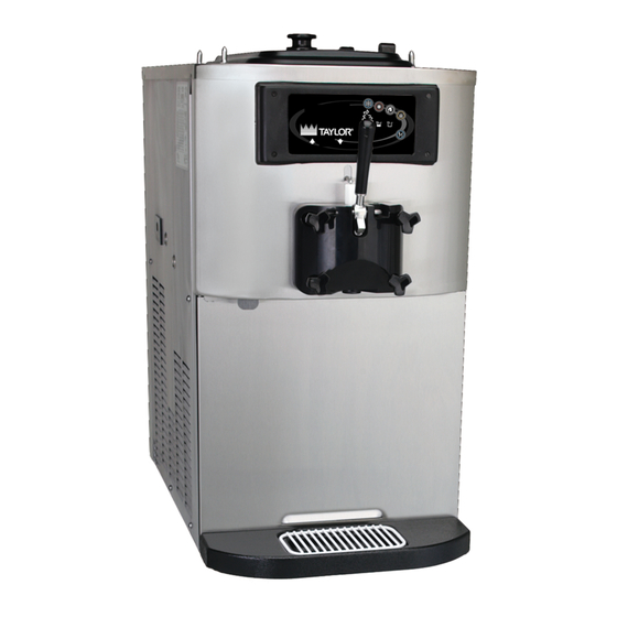
Model C708 Specifications Freezing Cylinder for availability. (For exact electrical information, always refer to the data label of the unit.) One, 3.4 quart (3.2 liter) Air Cooled Mix Hopper Clearance: A minimum of 6” (152 mm) is required on both sides, and the back of the unit placed against One, 20 quart (18.9 liter) -
Page 11: Model C709 Specifications
Net: 335 lbs. (152.0 kgs) Crated: 375 lbs. (170.1 kgs) This unit may be manufactured in other electrical characteristics. Refer to the local Taylor Distributor Volume: 30.6 cu. ft. (0.86 cu m) Note: Shown with optional air discharge chute. Figure 2 Introduction Models C708/C709/C716/C717... -
Page 12: Model C716 Specifications
*Mounted on standard casters Left Right Left Right 208--230/60/1 Air Approximate Weights 208--230/60/1 Water 208--230/60/3 Air Net: 778 lbs. (353 kgs) 220--240/50/1 Air Crated: 816 lbs. (370 kgs) 380--415/50/3N~Air Volume: 66.5 cu. ft. (1.88 cu. m.) Figure 3 Introduction Models C708/C709/C716/C717... -
Page 13: Model C717 Specifications
*Mounted on standard casters Left Right Left Right 208--230/60/1 Air Approximate Weights 208--230/60/3 Air 208--230/60/3 Water Net: 728 lbs. (330 kgs) 220--240/50/1 Air Crated: 766 lbs. (348 kgs) 380--415/50/3N~Air Volume: 66.5 cu. ft. (1.88 cu. m.) Figure 4 Introduction Models C708/C709/C716/C717... -
Page 14: General Installation Instructions
This deactivates the safety feature which prevents the operation of the machine C708 & C709: These units require a minimum of 6” when the door is not installed. (152 mm) air clearance on both sides, and the back of the unit placed against the wall to prevent Place the power switch in the ON position. -
Page 15: Models C708/C709/C716/C717
The syrup rail can be mounted to either the left or Press the PUMP symbol on the control panel. right side of the C708 or C709 units if a top air This will activate the pump motor only. discharge chute is used. -
Page 16: Models C708/C709/C716/C717
Figure 6 Install the (3) Nutserts (021106) in the panel. Install the (3) Holding Collars (046551) using the (3) Screws-10-32X3/4 OVAL HD-SS. Hang the Syrup Rail Assembly (048015-27) on the holding collars. Introduction Models C708/C709/C716/C717... -
Page 17: Running Specifications
Note: Make this adjustment with mix in the cylinder Be sure to allow adequate time for the pressure to and the freezer in the AUTO mode. Be sure to allow stabilize. adequate time for pressure to stabilize. Introduction Models C708/C709/C716/C717... -
Page 18: Important To The Operator
VACUUM FLUORESCENT DISPLAY KEYPADS MIX OUT INDICATOR STANDBY INDICATOR MIX LOW INDICATOR SELECT KEY SERVICE MENU KEY BRUSH CLEAN COUNTER ARROW KEYS SYRUP HEATER KEY NOTE: MODELS C709 & C717 DO NOT HAVE MIX PUMP KEYS. Figure 9 050622 Introduction Models C708/C709/C716/C717... -
Page 19: Models C708/C709/C716/C717
Your Taylor equipment is designed with these International symbols. ITEM DESCRIPTION ITEM DESCRIPTION AUTO DOWN ARROW HEAT CYCLE UP ARROW WASH HEATER MIX PUMP (C708/C716 ONLY) STANDBY MIX OUT MIX OUT STANDBY MIX LOW HEATER-RIGHT SIDE (C716/C717 ONLY) MIX PUMP MIX LOW WASH SELECT... -
Page 20: Models C708/C709/C716/C717
Indicator Lights Beater Motor Overload MIX LOW - When the MIX LOW symbol is C708/C709: The beater motor overload is located in illuminated, the mix hopper has a low supply of mix the service panel on the left side. and should be refilled as soon as possible. -
Page 21: Models C708/C709/C716/C717
Condenser Fan Motor (C708 & C716 Only) The condenser fan motor is driven by the software. C708: The reset button for the pump is located on The L1 to the fan is connected to the interface board the left side. -
Page 22: Models C708/C709/C716/C717
Notes: Introduction Models C708/C709/C716/C717... -
Page 23: Section 2: Controls, Systems And Operations
Freezer Lock-out Power Interrupt Pump Operation Timers Jumper Pins - UVC3 Beater Stir Cycles Setting Viscosity Control Overview Refrigeration System - Hot Gas Treatment Checking and Setting Refrigeration Valves Refrigeration Schematic Refrigeration System Components Controls, Systems and Operations Models C708/C709/C716/C717... -
Page 24: Universal Control Programming
Note: The displays illustrated in this section are those seen on the Models C708/C709. The Model C716/C717 versions may vary slightly. Power Up Memory (Initializing) Initializing System Data The seven segment display should display “00”... -
Page 25: Models C708/C709/C716/C717
The heat cycle data records are checked for integrity when the record is accessed, presently only through UNIT CLEANED the HEAT CYCLE DATA menu option. (For additional Heat Cycle Data information, see page 26.) Controls, Systems and Operations Models C708/C709/C716/C717... -
Page 26: Models C708/C709/C716/C717
When the entire heat cycle has been completed, the HEAT symbol will no longer be illuminated. The machine will enter the STANDBY mode (STANDBY symbol illuminates). The machine can be placed in Figure 13 AUTO or left in STANDBY. Controls, Systems and Operations Models C708/C709/C716/C717... -
Page 27: Models C708/C709/C716/C717
HEAT CYCLE DATA (8309) until all four numbers are displayed, then touch the SEL symbol. The Manager’s Menu list will SYSTEM INFORMATION display on the screen, provided the correct access CURRENT CONDITIONS code is entered. Controls, Systems and Operations Models C708/C709/C716/C717... -
Page 28: Models C708/C709/C716/C717
To disable the Daylight Saving Time NO CHANGES ALLOWED feature, touch the DOWN arrow to move the arrow Press Any Key to “Disable”. Then touch the SEL symbol to save the new setting. Controls, Systems and Operations Models C708/C709/C716/C717... -
Page 29: Models C708/C709/C716/C717
> Disable STANDBY MODE Enable the AUTO START TIME by touching the UP arrow symbol to move the arrow up to Enable. > EXIT Touch the SEL symbol to advance to the next screen. Controls, Systems and Operations Models C708/C709/C716/C717... -
Page 30: Models C708/C709/C716/C717
HPCO COMPRESSOR - Place the power switch in > Enable the OFF position. Wait 5 minutes for the machine to Disable cool. Place the power switch in the ON position and restart in AUTO. Controls, Systems and Operations Models C708/C709/C716/C717... -
Page 31: Models C708/C709/C716/C717
Use the arrow symbols to advance forward or move backward to view each screen. Listed below are the HPCO H/C - The high pressure switch opened variable messages that may appear. during the heat treatment cycle. Controls, Systems and Operations Models C708/C709/C716/C717... -
Page 32: Models C708/C709/C716/C717
41°F (5°C) during the COOL HRS SINCE HC phase. HRS SINCE 150 HC SINCE BC PEAK = Highest temperature reading for the hopper (h) and barrel (b) during the Heat Treatment Cycle. 051025 Controls, Systems and Operations Models C708/C709/C716/C717... -
Page 33: Models C708/C709/C716/C717
Listed below are variable failure code messages which could appear on line 2. SOFTWARE VERSION C708 CONTROL UVC3 VERSION 1.06 HEAT TIME FAILURE > Next Mix temperature did not rise above 151_F (66.1_C) in less than 90 minutes. -
Page 34: Models C708/C709/C716/C717
MIX LEVEL AUDIBLE Temp screen is displayed upon selecting this option. FAULT DESCRIPTION LOCKOUT HISTORY STANDBY TEMP HEAT CYCLE SUMMARY CUT IN AT 39.0 HEAT CYCLE DATA CURRENT 39.0 SYSTEM INFORMATION > Next CURRENT CONDITIONS 060821 Controls, Systems and Operations Models C708/C709/C716/C717... -
Page 35: Models C708/C709/C716/C717
HEATING 160.0 accepts the setting and returns to the Service Menu CURRENT 41.0 screen. Pressing the MENU symbol with any screen > Next showing ignores any changes and returns to the Service Menu screen. Controls, Systems and Operations Models C708/C709/C716/C717... -
Page 36: Models C708/C709/C716/C717
DELAY by one second respectively. Pressing the SEL symbol accepts the respectively. Pressing the SEL symbol accepts the setting and returns to the Service Menu screen. setting and returns to the Service Menu screen. Controls, Systems and Operations Models C708/C709/C716/C717... -
Page 37: Models C708/C709/C716/C717
Mix Pump Off Delay (C708 & C716 Only) Repeat the operation as described previously. Once the correct freezer Serial Number has been entered, pressing the SEL symbol displays the Store ID This option allows the technician to set the amount screen. -
Page 38: Models C708/C709/C716/C717
ARE YOU SURE? feature. > MANUAL CONTROL ERROR MACHINE MUST Figure 15 BE IN (OFF) MODE PRESS SEL KEY Moving the cursor to YES and selecting the Calibration key will restore all factory default values. 060821 Controls, Systems and Operations Models C708/C709/C716/C717... -
Page 39: Heat Treatment Cycle
HEAT phase of the Heat Treatment Cycle. If the that the machine is operating in the STANDBY timer exceeds 90 minutes, the unit will lock-out. mode. Controls, Systems and Operations Models C708/C709/C716/C717... -
Page 40: Heat Treatment Graph
41_F (5_C). At this point the machine enters Standby operation. While the time given for the COOL Phase is 90 minutes, the actual time is closer to 30 minutes. Figure 15 Controls, Systems and Operations Models C708/C709/C716/C717... -
Page 41: Freezer Lock-Out
FREEZER LOCKED Cylinder or Hopper) occurred during a Heat cycle. The following screen will be displayed if a Brush Clean Cycle Time has occurred. BRUSH CLEAN TIMEOUT FREEZER LOCKED CLEANING REQ’D > BRUSH CLEAN Controls, Systems and Operations Models C708/C709/C716/C717... -
Page 42: Models C708/C709/C716/C717
If a PRODUCT OVER TEMPERATURE condition lock is indicated on the second line. occurs during operation, the following screen will appear. NO HEAT CYCLE START PRODUCT OVER TEMP REASON > HEAT CYCLE > HEAT CYCLE BRUSH CLEAN BRUSH CLEAN Controls, Systems and Operations Models C708/C709/C716/C717... -
Page 43: Models C708/C709/C716/C717
Once the timer counts down to zero, the lockout is Note: A record of Heat Cycle Data and Lock Out cleared. History can be found in the Manager’s Menu. Controls, Systems and Operations Models C708/C709/C716/C717... -
Page 44: Power Interrupt
Completion of a successful brush clean resets the UNIT CLEANED Brush Clean Cycle timer and removes the locked condition. A new brush clean date is calculated the first time that the Auto or Standby mode is entered. Controls, Systems and Operations Models C708/C709/C716/C717... -
Page 45: Pump Operation
Screw-1/4-20 x 3/4 020128-2 Sleeve A.-Mix Pump X44761 Motor-Reducer (50/60 Soft Serve) 036955-34 Coupling-Motor-Flexible 047936 Motor (Soft Serve) 049246-34 Seal-Input 048836 Gear (50/60 Hz Soft Serve) 049247-34 Seal-Output 048837 Mount-Motor 036934 Nut-Pump Sleeve 036933 *Not Shown Controls, Systems and Operations Models C708/C709/C716/C717... -
Page 46: Timers
Heat Phase of the Heat Treatment Cycle (90 minutes). If the timer This timer times out 5 minutes when all conditions exceeds 90 minutes, the unit will lock out. for a successful brush cleaning are met. Controls, Systems and Operations Models C708/C709/C716/C717... -
Page 47: Jumper Pins - Uvc3
If a jumper is present on the left interface board, it resets the brush clean date. If a jumper is present on the right interface board, it enables the 59°F (15°C) product temperature fault. 060207 Controls, Systems and Operations Models C708/C709/C716/C717... -
Page 48: Beater Stir Cycles
As the product freezes may range from 16_F to 19_F (-8.8_C to -7.2_C). (thickens), the amperage load increases. When the amperage load reaches the setpoint, the refrigeration cycle discontinues. VISCOSITY SETTING VISC AMPS CURRENT Controls, Systems and Operations Models C708/C709/C716/C717... -
Page 49: C708/C709 Control Overview
C708/C709 Control Overview Systems, Controls and Operations Models C708/C709/C716/C717... -
Page 50: C716/C717 Control Overview
C716/C717 Control Overview Systems, Controls and Operations Models C708/C709/C716/C717... -
Page 51: Refrigeration System - Hot Gas Treatment
Cool Phase. Both liquid line solenoids are closed during the Hot Gas Heat Note: This information applies to both sides on the Phase. C716 and C717 - independent systems. Systems, Controls and Operations Models C708/C709/C716/C717... -
Page 52: Checking And Setting Refrigeration Valves
DBV valve to 10 - 11 psi (69 - 76 kPa) by reading the suction gauge at the service valves. Adjust the EPR valve to 60 psi (414 kPa) by reading the suction gauge on the EPR access fitting. Systems, Controls and Operations Models C708/C709/C716/C717... -
Page 53: Refrigeration Schematic
Refrigeration Schematic Systems, Controls and Operations Models C708/C709/C716/C717... -
Page 54: Refrigeration System Components
Alco, OPR-10, Outlet Pressure Downstream Regulator - 057008 Liquid injection valve, TREV 3/8 x 3/8 220 *161* - 055378 Discharge bypass valve - 046365 (AXV) Filter/Dryer Dryer-Filter-HP62-3/8 x 1/4S - 048901 Heat Exchanger 15.25 joined length Receiver Accumulator - 047062 Systems, Controls and Operations Models C708/C709/C716/C717... -
Page 55: Models C708/C709/C716/C717
SV06 Discharge bypass line Prevents leakage of Opens any time the hopper is solenoid valve refrigerant past the DBV. being cooled. Systems, Controls and Operations Models C708/C709/C716/C717... -
Page 56: Models C708/C709/C716/C717
Receiver The liquid receiver is a The use of a liquid reciever storage tank for liquid makes the quantity of refrigerant. refrigerant in a system less critical. Systems, Controls and Operations Models C708/C709/C716/C717... -
Page 57: Section 3: Troubleshooting
Section 3: Troubleshooting General Troubleshooting Electrical Troubleshooting Pump Style Freezer Troubleshooting Solenoid Valve Failure Troubleshooting Bacteria Troubleshooting Troubleshooting Models C708/C709/C716/C717... -
Page 58: General Troubleshooting Guide
Worn or missing drive shaft seal. a. If worn, nicked or missing, replace the rear of the unit into the drip the drive shaft seal. pan. b. Inadequate lubrication. b. Lubricate properly. c. Drive shaft rotates forward. c. Check gear alignment. Troubleshooting Models C708/C709/C716/C717... -
Page 59: Models C708/C709/C716/C717
Fill hopper with mix. freezing cylinder. out light is lit). b. Air/mix pump incorrectly b. Assemble pump according to assembled (C708/C716). instructions in the Operator’s Manual. c. Incorrect usage of the mix feed c. Follow the correct feed tube tube (C709/C717). -
Page 60: Models C708/C709/C716/C717
Set the draw rate at 5 - 7-1/2 ounces of product per 10 seconds. b. Pump is assembled/lubed b. Assemble pump according to incorrectly (C708/C716). instructions in the Operator’s Manual. c. Freezer has been turned on and c. Place the unit in the “OFF” position off several times. -
Page 61: Models C708/C709/C716/C717
The 24V relay is faulty. d. Replace the relay. e. The agitator motor is faulty. e. Replace the motor. There is low voltage from the 24V Check the power supply transformer. connections, shorts, replace transformer. Troubleshooting Models C708/C709/C716/C717... -
Page 62: Electrical Troubleshooting Guide
Electrical Troubleshooting Guide MODES OF OPERATION: COMPONENT HEAT STANDBY WASH AUTO PUMP Heat Hold Cool Compressor Beater Motor Air/Mix Pump Motor Agitator Troubleshooting Models C708/C709/C716/C717... -
Page 63: C708/C709 Electrical Troubleshooting Guide
C708/C709 Electrical Troubleshooting Guide Power Cord Plugged In/Power Switch in the To operate the agitator, L1 is supplied to the agitator OFF Position motor power transformer (24V) from the power switch. The transformer supplies power to terminal L1 power from the power cord connection travels J5, pin 1 of the interface board. -
Page 64: C716/C717 Electrical Troubleshooting Guide
3 for the hopper liquid solenoid and hot gas bypass (DBV) 2 - Agitator Motor 2 for the barrel liquid solenoid 1 - Barrel Hot Gas Solenoid Relay 1 for the compressor contactor coil 2 - Hopper Hot Gas Solenoid Relay Troubleshooting Models C708/C709/C716/C717... -
Page 65: Pump Style Freezer Troubleshooting
Lubricate properly. of pump cylinder. b. Ball crank rotates clockwise. b. Rewire ball crank rotation to rotate counterclockwise. 3. Not enough pressure in the a. Malfunctioning draw switch. a. Reposition or replace the freezing cylinder. microswitch. Troubleshooting Models C708/C709/C716/C717... -
Page 66: Solenoid Valve Failure Troubleshooting
Will fail heat cycle, cool phase. Product will not cool in Auto or Standby modes. Suction pressure is below DBV setting with hopper only cooling. b. Stuck Open/Leaking: Will fail the heat cycle in the heat phase. In Auto or Standby modes, the hopper product cools to 32°F (0°C). Troubleshooting Models C708/C709/C716/C717... -
Page 67: Models C708/C709/C716/C717
Too high will cause over amping of the compressor in the heat cycle heat phase and high pressure cut out in the cool phase. The OPR is very sensitive to high ambient conditions. Must be set in the ambient the machine will run in. TXV: The TXV is not adjustable. Troubleshooting Models C708/C709/C716/C717... -
Page 68: Bacteria Troubleshooting
After sanitizing a freezer, use fresh mix to flush remaining sanitizer from the freezing cylinder. b. Provide the proper brushes, lubricants, and single service towels. c. Store sanitizer in a cool, dry place. Use chemicals according to their labels. Troubleshooting Models C708/C709/C716/C717... -
Page 69: Models C708/C709/C716/C717
45_F. will allow cell division in as little as one hour. f. Once the mix is placed in the hopper, covers must be properly installed to maintain adequate refrigeration and to prevent airborne contaminants from entering the mix. Troubleshooting Models C708/C709/C716/C717... -
Page 70: Models C708/C709/C716/C717
Notes: Troubleshooting Models C708/C709/C716/C717... -
Page 71: Section 4: Parts
Section 4: Parts Parts Warranty Explanation Parts Identification Parts List Wiring Diagrams Parts Models C708/C709/C716/C717... -
Page 72: Parts Warranty Explanation
NOTE: Taylor reserves the right to deny warranty claims on equipment or parts if a non-approved refrigerant was installed in the machine, system modifications were performed beyond factory recommendations, or it is determined that the failure was caused by neglect or abuse. NOTE: See your Authorized Taylor Distributor for possible labor warranty. Parts Models C708/C709/C716/C717... -
Page 73: Models C708/C709/C716/C717
Notes: Parts Models C708/C709/C716/C717... -
Page 74: Model C708 Exploded View
Model C708 Exploded View Parts Models C708/C709/C716/C717... -
Page 75: Models C708/C709/C716/C717
Model C708 Exploded View Parts Identification ITEM DESCRIPTION PART NO. ITEM DESCRIPTION PART NO. SHELL A.-INSULATED X56969 VALVE-SOLENOID 7/640RF 043449-27 BEARING-REAR SHELL-NICK 031324 VALVE-SOL 1/8ORF 1/4 IN 053511-27 WASHER-BEARING LOCK 012864 VALVE-EXP-AUTO-1/4S X1/4 046365 NUT-BRASS BEARING 028991 VALVE-THERMOSTATIC 057002 GUIDE-DRIP SEAL 028992 PROBE A.-MIX... -
Page 76: Models C708/C709/C716/C717
Model C708 Exploded View Parts Identification (Continued) ITEM DESCRIPTION PART NO. ITEM DESCRIPTION PART NO. HOUSING A.-AGITATOR X56586-03 BODY-AGITATOR HOUSING 056588 CAP-AGITATOR HOUSING 056589 *62h SCREW-8-32 X 3/16 ALLEN 006812 O-RING-1-3/8 OD X .070W 017395 PUMP A.-MIX SIMPLIFIED S.S. X57029-14 MAGNET A.-AGITATOR... -
Page 77: Operator Parts (Model C708)
Operator Parts (Model C708) ITEM DESCRIPTION PART NO. ITEM DESCRIPTION PART NO. PANEL-SIDE-LEFT 056963 SCREW-1/4-20X3/8 RHM-STNLS 011694 PAN-DRIP 11-5/8 LONG 027503 PANEL A-SIDE-RIGHT X57871 PIN-RETAINING-HOPPER CVR 043934 PANEL A.-FRONT-UPPER X57017 COVER-HOPPER *BLACK 053809-1 PANEL A.-FRONT-LOWER X56954 BLADE A.-AGITATOR X56591 STUD-NOSE CONE 055987 PUMP A.-MIX SIMPLIFIED S.S. -
Page 78: Model C709 Exploded View
Model C709 Exploded View Parts Models C708/C709/C716/C717... -
Page 79: Models C708/C709/C716/C717
VALVE-EPR 057009 STUD-NOSE CONE 055987 VALVE-SOLENOID 7/16 ORF 048626-27 BRACKET-CONTROL BOX 056927 LINE A.-DRYER/VALVES X59352-27 CONTROL A. X59240-27 DRYER-FILTER-HP62-3/8 048901 COVER-CONTROL BOX 056929 VALVE-TREV 3/8 X 3/8 220 055378 BLADE A.-AGITATOR X56591 VALVE-SOLENOID 7/640RF 043449-27 *NOT SHOWN Parts Models C708/C709/C716/C717... -
Page 80: Models C708/C709/C716/C717
SCREW-4-40 X 1/4 SOC SS 600165 SWITCH A.-DRAW X56147 PLATE-HOLDING-AGITATOR 056587 HOUSING A.-AGITATOR X56586-03 MOTOR-AGITATOR-24VAC 050535-03 CAP-AGITATOR HOUSING 056589 BODY-AGITATOR HOUSING 056588 O-RING-1-3/8 OD X .070W 017395 *62h SCREW-8-32 X 3/16 ALLEN 006812 MAGNET A.-AGITATOR X57341 PROBE-MIX OUT 056908 *NOT SHOWN Parts Models C708/C709/C716/C717... -
Page 81: Operator Parts (Model C709)
PANEL A.-FRONT-UPPER X59423 PIN-RETAINING-HOPPER CVR 043934 PANEL A.-FRONT-LOWER X58955 COVER-HOPPER *BLACK 053809-1 STUD-NOSE CONE 055987 BLADE A.-AGITATOR X56591 SHELF-TRAY-DRIP 056076 TUBE A.-FEED-OUTER-HT X34641 TRAY-DRIP 056858 PANEL-REAR 056077-SP1 SHIELD-SPLASH 049203 ORIFICE 022465-100 TUBE A.-FEED-SC-INNER X32824-2 SCREW-1/4-20X3/8 RHM-SS 011694 Parts Models C708/C709/C716/C717... -
Page 82: Model C716 Exploded View
Model C716 Exploded View Parts Models C708/C709/C716/C717... -
Page 83: Models C708/C709/C716/C717
VALVE-TREV 3/8 X 3/8 220 055378 RECEIVER A.-RIGHT*COPE X59968 VALVE A.-AXV-HOT GAS*LEFT X59939-27 RECEIVER A.-LEFT*COPE-A X59967 VALVE-EXP-AUTO-1/4S X 1/4 046365 EXCHANGER A.-HEAT-R. X59966 VALVE-SOLENOID 7/64 ORF 043449-27 VALVE A.-LIQUID *RIGHT X59964-27 VALVE-SOL 1/8 ORF 1/4 IN X 3/8 053511-27 Parts Models C708/C709/C716/C717... -
Page 84: Models C708/C709/C716/C717
PUMP A.-MIX SIMPLIFIED S.S. X57029-14 LINE A.-DBV *LEFT X59961-27 BLOWER-HIGH OUTPUT-HTGS 059750-27 VALVE-EXP-AUTO-1/4S X 1/4 046365 GUIDE A.-FILTER-LEFT X59931 VALVE-SOLENOID 7/64 ORF 043449-27 ACTUATOR-DRAW SWITCH X62401 BLADE A.-AGITATOR X56591 SWITCH A.-DUAL LEVER X62400 HOUSING A.-AGITATOR X56586-03 SWITCH-TOGGLE-3PDT 032532 Parts Models C708/C709/C716/C717... -
Page 85: Operator Parts (Model C716)
TRAY-DRIP-19-5/8 L X 4-7/8 033812 PUMP A.-MIX SIMPLIFIED X57029-14 SHIELD-SPLASH-WIRE-19-3/4 L 033813 PANEL-SIDE-RIGHT 059907 PAN-DRIP 19-1/2 LONG 035034 PANEL A.-FRONT X59920 STUD-NOSE CONE 055987 PANEL A.-FRONT X59836 PIN-RETAINING-HOPPER CVR 043934 PAN-DRIP 12.5 059736 PANEL-SIDE-LEFT 059906 FILTER-AIR-POLY-FLO 052779-11 Parts Models C708/C709/C716/C717... -
Page 86: Model C717 Exploded View
Model C717 Exploded View Parts Models C708/C709/C716/C717... -
Page 87: Models C708/C709/C716/C717
RECEIVER A.-COPE L-A/C X63030 VALVE-SOL 1/8 ORF 1/4” X 3/8 053511-27 EXCHANGER A.-HEAT-R. X63022 VALVE A.-TXV-LEFT X63037 VALVE A.-LIQUID *RIGHT X63028-27 EXCHANGER A.-HEAT-L. X63031 DRYER-FILTER 3/8 X 3/8 SOL 049154 PLATE A.-DEC X62128 VALVE-TREV 3/8 X 3/8 220 055378 Parts Models C708/C709/C716/C717... -
Page 88: Models C708/C709/C716/C717
056588 VALVE-ACCESS-1/4 MFL X 3/8 053565 PROBE A.-MIX X56912 SWITCH-PRESSURE 440 PSI 048230 SPACER-PROBE-MIX-UPPER 056910 LINE A.-DBV *LEFT X63033-27 PROBE-MIX OUT 056908 VALVE-EXP-AUTO-1/4S X 1/4 046365 SPACER-PROBE-MIX-MIDDLE 056907 VALVE-SOLENOID 7/64 ORF 043449-27 SPACER-PROBE-MIX 056985 BLADE A.-AGITATOR X56591 Parts Models C708/C709/C716/C717... -
Page 89: Operator Parts (Model C717)
SCREW-1/4-20 X 3/8 RHM-SS 011694 O-RING-.643 OD X .077 W 018572 DEFLECTOR-BLOWER EXHAUS 059929 PANEL-REAR 059917 SHIELD-SPLASH-WIRE-19-3/4 L 033813 PANEL-SIDE*RIGHT 059907 TRAY-DRIP-19-5/8 L X 4-7/8 033812 PAN-DRIP 12.5 059736 PAN-DRIP 19-1/2 LONG 035034 PANEL A.-FRONT X59920 PANEL-SIDE-LEFT 059906 Parts Models C708/C709/C716/C717... -
Page 90: Control A. - X59239- (Model C708)
Control A. - X59239- (Model C708) ITEM DESCRIPTION PART NO. ITEM DESCRIPTION PART NO. BUSHING-SNAP 1-5/16ID 017008 NUT-OVERLOAD RESET 045026 PCB A.-CONTROL X59209-SER OVERLOAD-TI #2BM-20V9R 044464 CHIP-SOFTWARE C708 UVC3 X40828 BRACKET-PUMP OV-SGL 044465 CONTROL-UVC3 SURFACE MT 062529 BRACKET-CONTRACTOR MNT 056928... -
Page 91: Control A. - X59240- (Model C709)
SCREW-6X5/16 RD HD TYP B 013646 SCREW-8X1/4 SL HEX HD 009894 SOCKET-RELAY-FOR US 052112 BUSHING-SNAP 1-5/8ID X 2 OD 043637 TRANS.-CONT.-32VA 120/200/2 054834 SCREW-10 X 3/8 TYPE B-SERR 015582 TRANS.-120/208/240V PRI 24V 051660 TERMINAL-RING #10 18-22WIR 023531 CAPACITOR-MOTOR-AGITAT 057525 Parts Models C708/C709/C716/C717... -
Page 92: Control A. - X59497- (Model C716)
BUSHING-SNAP 5/8ID X 3/4 017462 CAPACITOR-MOTOR-AGITATR 057525 TRANS.-CONT.-32VA 120/200/ 054834 BUSHING-SNAP 1-5/8IDX2 OD 043637 BARRIER-SHIELD 062601 SCREW-6X5/16 RD HD TYP B 013646 CHIP-SOFTWARE C716 UVC X40890 FUSE-15A 250 VAC CERAMIC 062352 COVER-CONTROL BOX 062599 BLOCK-TERMINAL AND FUSE 062351 *NOT SHOWN Parts Models C708/C709/C716/C717... -
Page 93: Control A. - X59498- (Model C717)
FUSE-15A 250 VAC CERAMIC 062352 TRANS.-CONT.-32VA 054834 BLOCK-TERMINAL AND FUSE 062351 120/200/24 CAPACITOR-MOTOR-AGITATR 057525 BARRIER-SHIELD 062601 BUSHING-SNAP 1-5/8ID X 2 043637 CHIP SOFTWARE C716 UVC3 X40890 SOCKET-RELAY-FOR US 052112 COVER-CONTROL BOX 062599 RELAY-DPDT 100UA TO 7A 1/8 052111-03 *NOT SHOWN Parts Models C708/C709/C716/C717... -
Page 94: Box A.-Cap & Relay - X56931-27 (Model C708)
Box A.-Cap & Relay - X56931-27 (Model C708) ITEM DESCRIPTION PART NO. ITEM DESCRIPTION PART NO. BLOCK-TERMINAL 3P 20A, 300V 051331 RELAY-MTR START 039725-27 TI#4CR-1-625 SCREW-8X1/4 SL HEX HD B 009894 CONNECTOR-BX 3/4 STR- 031231 CAPACITOR-START 033044-1 SCREW-10X3/8TYPEB-HWH 015582 189-227UF/33... -
Page 95: Box A.-Cap & Relay - X58849-27 (Model C709)
ITEM DESCRIPTION PART NO. ITEM DESCRIPTION PART NO. BLOCK-TERMNL 3P 20A, 300V 051331 STRAP-CAPACITOR 7-11/32 037890 SCREW-8X1/4 SL HEX HD B 009894 SCREW-10X3/8TYPEB-HWH 015582 CAPACITOR-START 053106 CAPACITOR-RUN 35UF/440V 048132 189-227UF/25 RELAY-START-COMPRESSOR 051957-27 CONNECTOR-BX 3/4 STR-2 SC 031231 Parts Models C708/C709/C716/C717... -
Page 96: Box A.-Cap & Relay - X59499-27 (Model C716)
PART NO. CAPACITOR-START 033044-1 SCREW-8-32X3/8 TAPTITE-HEX 041951 189-227UF/33 RELAY-START-COMPRESSOR 052401-27 CAPACITOR-RUN 40MF/440V 036049 SCREW-6-32X1-1/4 RD HD 017310 STRAP-CAPACITOR 7-11/32 037890 BLOCK-TERMINAL 2P L1,L2 039422 SCREW-6-32X5/8 TAPTITE PAN 041250 LUG-GROUNDING 4-14GA 017667 CONNECTOR-BX 3/4 STR-2 031231 WIRE SCREW Parts Models C708/C709/C716/C717... -
Page 97: Box A.-Cap & Relay - X59500-27 (Model C717)
PART NO. CAPACITOR-START 053106 SCREW-8-32X3/8 TAPTITE-HEX 041951 189-227UF/25 RELAY-START-COMPRESSOR 051957-27 CAPACITOR-RUN 35UF/440V 048132 SCREW-6-32X1-1/4 RD HD 017310 STRAP-CAPACITOR 7-11/32 037890 BLOCK-TERMINAL 2P L1,L2 039422 SCREW-6-32X5/8 TAPTITE PAN 041250 LUG-GROUNDING 4-14GA 017667 CONNECTOR-BX 3/4 STR-2 031231 WIRE SCREW Parts Models C708/C709/C716/C717... -
Page 98: Switch A.-Draw - X56147 (C708/C709)
Switch A.-Draw - X56147 (C708/C709) ITEM DESCRIPTION PART NO. ITEM DESCRIPTION PART NO. SCREW-4-40X1 RD HD STEEL 028890 SPRING-RETURN-LEFT- 041660 SWITCH-LEVER-SPDT-10A-125 028889 ARM A.-DRAW X56253 BRACKET A.-SWITCH X56254 E-RING 3/16 .335 O.D. 049178 PIN-PIVOT 015478 NUT-4-40 HEX -PLATED 038623 SPRING-RETURN-RIGHT... -
Page 99: Switch A.-Dual Lever - X62400 (C716/C717)
Switch A.-Dual Lever - X62400 (C716/C717) ITEM DESCRIPTION PART NO. ITEM DESCRIPTION PART NO. SCREW-4-40X1” TAPTITE PAN 045141 BRACKET-SWITCH 062394 ACTUATOR-TANDEM LEAF 062408 SWITCH-LEVER-SPDT-10A-125 028889 Parts Models C708/C709/C716/C717... -
Page 100: Actuator A.-Draw Switch - X62401 (C716/C717)
Actuator A.-Draw Switch - X62401 (C716/C717) ITEM DESCRIPTION PART NO. ITEM DESCRIPTION PART NO. SPRING-RETURN-LEFT-TWIN 038923 E-RING 1/4 032190 TWIST ARM-SWITCH-DRAW-R 038650 BRACKET A.-SPRING RETURN X38257 ARM-SWITCH-DRAW-L 038649 SPRING-RETURN-RIGHT-TWIN 038924 ROD-SPRING RETAINER 038254 TWIST SPRING-EXTENSION.375X.045 038922 PIN-PIVOT-DRAW SWITCH 038484 BRACKET-SWITCH 038253 Parts Models C708/C709/C716/C717... -
Page 101: Pump A.-Mix Simplified - X57029- (C708/C716)
Pump A.-Mix Simplified - X57029- (C708/C716) ITEM DESCRIPTION PART NO. ITEM DESCRIPTION PART NO. 1 - - 7 PUMP ASSEMBLY - MIX X57029-XX* CRANK-DRIVE 039235 SIMPLIFIED SOFT SERVE SHAFT-DRIVE 041948 CYLINDER-PUMP-HOPPER-SS 057943 O-RING - DRIVE SHAFT 048632 PIN A.-RETAINING X55450... -
Page 102: Door And Beater Assembly (Model C708
Door and Beater Assembly (Model C708) ITEM DESCRIPTION PART NO. ITEM DESCRIPTION PART NO. HANDLE A.-DRAW-WELDED X56246 SHOE-FRONT HELIX *FRONT* 050347 NUT-STUD SHORT (2) 058764 BEATER A.-3.4QT-1 PIN X46231 DOOR A.-W/BAFFLE X57332-SER BLADE-SCRAPER-PLASTIC 046235 VALVE A.-DRAW X55820 CLIP-SCRAPER BLADE 7.00 046236 O-RING-DRAW VALVE-S.S. -
Page 103: Door And Beater Assembly (Model C709
GASKET-DOOR HT 4”-DBL 048926 SCREW-ADJUSTMT-5/16-24 056332 BEARING-FRONT 050216 NUT-STUD BLACK 3.250” 058765 BEATER A.-3.4 QT HELICORE X31761 NUT-STUD BLACK 2.563“ 058764 BLADE-SCRAPER-PLASTIC 035174 DOOR A.-W/BAFFLE X57332-SER SHAFT-BEATER 056078 VALVE A.-DRAW X55820 SEAL-DRIVE SHAFT 032560 O-RING-DRAW VALVE-S.S. 014402 Parts Models C708/C709/C716/C717... -
Page 104: Plate A.-Dec - X56959 (C708) / X58860 (C709
Plate A.-Dec - X56959 (C708) / X58860 (C709) ITEM DESCRIPTION PART NO. ITEM DESCRIPTION PART NO. PLATE-DEC (MODEL C708) 056958 GASKET-DEC PLATE 056991 PLATE-DEC (MODEL C709) 058859 WASHER-#6 FLAT STNLS 023546 CABLE-USB 056785 SCREW-6-32X7/8 RHM 007017 HARNESS-WIRE-5V SHIELDED 057729 PCB A.-INTERFACE... -
Page 105: Door And Beater Assembly (Model C716
BEATER A.-3.4QT-1 PIN X46231 GASKET-DOOR HT 4”-DOUBLE 048926-1 SHAFT-BEATER 032564 O-RING--7/8 OD X .103W 014402 SEAL-DRIVE SHAFT 032560 VALVE A.-DRAW X59888 O-RING-1/4 OD X .070W 50 015872 VALVE A.-DRAW*CENTER X59890 SCREW-ADJUSTMENT-5/16-24 056332 SHOE-FRONT HELIX *FRONT* 050347 060221 Parts Models C708/C709/C716/C717... -
Page 106: Door And Beater Assembly (Model C717
NUT-STUD BLACK 3.250 LONG 058765 SEAL-DRIVE SHAFT 032560 NUT-STUD BLACK 2.563 LONG 058764 VALVE A.-DRAW-L&R X59888 DOOR A.-*LG BAF*W/O PRG X59924-SER VALVE A.-DRAW-CENTER X59890 PIN-HANDLE-TWIN 059894 SEAL-DRAW VALVE 034698 GASKET-DOOR HT 4”-DOUBLE 048926-1 O-RING-7/8 OD X .103W 014402 BEARING-FRONT 050216 060221 Parts Models C708/C709/C716/C717... -
Page 107: Plate A.-Dec - X62127 (C716) / X62128 (C717
Plate A.-Dec - X62127 (C716) / X62128 (C717) ITEM DESCRIPTION PART NO. ITEM DESCRIPTION PART NO. PLATE-DEC *SYRUP RAIL 062123 INSULATOR-PCB-INTERFACE 057168 (C716) SCREW-6-32X3/8 BIN.HD 002201 PLATE-DEC *SYRUP RAIL 062124 SLOT (C717) CABLE-RIBBON-14C-3”L-SIL 056864 PCB A.-INTERFACE X62101-SER Parts Models C708/C709/C716/C717... -
Page 108: Accessories
X56085 TOOL-O-RING REMOVAL 048260-WHT KIT A.-TUNE-UP (C709) X49463-58 TOOL-SHAFT-DRIVE PUMP 057167 KIT A.-TUNE-UP (C716) X49463-82 (C708/C716) KIT A.-TUNE-UP (C717) X49463-79 LUBRICANT-TAYLOR HI-PERF 048232 KIT A.-PARTS TRAY (C708) X57797 PAIL-MIX 10 QT. 013163 KIT A.-PARTS TRAY (C716) X58449 Parts Models C708/C709/C716/C717... -
Page 109: Models C708/C709/C716/C717
Brush Kit Assembly X44127 (C708/C716) ITEM DESCRIPTION PART NO. ITEM DESCRIPTION PART NO. BLACK BRISTLE BRUSH 013071 BRUSH SET (3) 050103 DOUBLE END BRUSH 013072 YELLOW BRISTLE BRUSH 039719 WHITE BRISTLE BRUSH 013073 WHITE BRISTLE BRUSH 023316 (1” x 2”) (3”... -
Page 110: Models C708/C709/C716/C717
Brushes - C709/C717 ITEM DESCRIPTION PART NO. ITEM DESCRIPTION PART NO. BRUSH-REAR BEARING 013071 BRUSH-WHITE BRISTLE 3” X 7” 023316 BRUSH-DOUBLE-ENDED 013072 BRUSH-END-DOOR SPOUT 039719 BRUSH-WHITE BRISTLE 1” X 2” 013073 Parts Models C708/C709/C716/C717... -
Page 111: Parts List
Parts List + Available Separately Models C708/C709/C716/C717 Parts List... -
Page 112: Parts List
+ Available Separately Parts List Models C708/C709/C716/C717... -
Page 113: Parts List
+ Available Separately 060221 Models C708/C709/C716/C717 Parts List... -
Page 114: Parts List
+ Available Separately Parts List Models C708/C709/C716/C717... -
Page 115: Parts List
+ Available Separately 060221 Models C708/C709/C716/C717 Parts List... -
Page 116: Parts List
+ Available Separately Parts List Models C708/C709/C716/C717... -
Page 117: Parts List
+ Available Separately Models C708/C709/C716/C717 Parts List... -
Page 118: Parts List
+ Available Separately Parts List Models C708/C709/C716/C717... -
Page 119: Parts List
+ Available Separately Models C708/C709/C716/C717 Parts List... -
Page 120: Parts List
+ Available Separately Parts List Models C708/C709/C716/C717... -
Page 121: Parts List
+ Available Separately Models C708/C709/C716/C717 Parts List... -
Page 122: Parts List
+ Available Separately Parts List Models C708/C709/C716/C717... -
Page 123: Parts List
+ Available Separately Models C708/C709/C716/C717 Parts List... -
Page 124: Parts List
+ Available Separately Parts List Models C708/C709/C716/C717... -
Page 125: Parts List
+ Available Separately 060221 Models C708/C709/C716/C717 Parts List... -
Page 126: Parts List
+ Available Separately Parts List Models C708/C709/C716/C717... -
Page 127: Parts List
+ Available Separately 060221 Models C708/C709/C716/C717 Parts List... -
Page 128: Parts List
+ Available Separately Parts List Models C708/C709/C716/C717... -
Page 129: Parts List
+ Available Separately Models C708/C709/C716/C717 Parts List... -
Page 130: Parts List
+ Available Separately Parts List Models C708/C709/C716/C717... -
Page 131: Parts List
+ Available Separately Models C708/C709/C716/C717 Parts List... -
Page 132: Parts List
+ Available Separately Parts List Models C708/C709/C716/C717... - Page 133 C708/C709 057010-27 Rev. 6/05...
- Page 134 C708/C709 057010-33 Rev. 6/05...
- Page 135 C708/C709 057010-40 Rev. 6/05...
- Page 136 C708/C709 057010-58 Rev. 6/05...
- Page 137 Model C716 059900-27 Rev. 2/06...
- Page 138 Model C716 059900-27 Inset 1 2/06...
- Page 139 Model C716 059900-27 Inset 2 2/06...
- Page 140 Model C716 059900-33 Rev. 2/06...
- Page 141 Model C716 059900-40 Rev. 2/06...
- Page 142 Model C716 059900-58 Rev. 2/06...
- Page 143 Model C717 059901-27 6/05...
- Page 144 Model C717 059901-27 Inset 1 6/05...
- Page 145 Model C717 059901-27 Inset 2 6/05...
- Page 146 Model C717 059901-33 6/05...
- Page 147 Model C717 059901-40 6/05...
- Page 148 Model C717 059901-58 6/05...