
Related Manuals for American Standard ACONT602AF22MA


Summary of Contents for American Standard ACONT602AF22MA
- Page 1 ACONT602AF22MA Programmable Comfort Control Installation Instructions Pub. No. 11-HD02D11-3 69-1833-02...
- Page 2 Product Application This Comfort Control provides electronic control of 24 VAC single-stage and multi- stage heating and cooling systems. System Types Power (up to 2 heat/2 cool) • Common wire only • Gas, oil or electric heat with • Common wire with battery backup air conditioning Changeover Options •...
-
Page 3: Table Of Contents
Table of contents Installation Appendices Pre-installation checklist ....2 Quick reference to controls ..12 Wallplate installation ...... 3 Quick reference to display ... 12 Wiring ..........4 Battery replacement ..... 12 Wiring diagrams ......5 In case of difficulty ....... 13 Power options ........ -
Page 4: Pre-Installation Checklist
Pre-installation checklist Package contents Check to make sure your package includes the following items: Quick Programmable Owner's Guide reference Comfort Control card (wallplate attached to back) Wall anchors and AA alkaline mounting screws (2 batteries (2) each) Required tools & supplies •... -
Page 5: Wallplate Installation
Wallplate installation Remove battery holder. Remove the wallplate from the Comfort Control as shown at left, then Pull here to remove wallplate follow directions below for mounting. from new Comfort Control. 1 Insert quick reference card in slot in back of Comfort Control. 2 Pull wires through wire hole. -
Page 6: Wiring
Wiring CAUTION: ELECTRICAL HAZARD. Can cause electrical shock or equipment damage. Disconnect power before wiring. Wiring Keep wires in this shaded area 1 Loosen screw terminals, insert wires into terminal block, then re-tighten screws. 2 Push excess wire back into the wall opening. -
Page 7: Wiring Diagrams
Wiring diagrams Factory-installed jumper. Remove for 2-transformer systems only. • Provide Power Supply disconnect means and overload protection as required. Typical 1H/1C system: 1 transformer Typical 1H/1C system: 2 transformers SINGLE STAGE GAS FURNACE – SINGLE STAGE COOLING SINGLE STAGE OIL FURNACE – SINGLE STAGE COOLING SINGLE STAGE SINGLE STAGE 602 COMFORT CONTROL... - Page 8 Wiring diagrams Factory-installed jumper. Remove for 2-transformer systems only. • Provide Power Supply disconnect means and overload protection as required Typical 2H/2C system (1 transformer) Typical 2H/1C heat pump system TWO STAGE VARIABLE SPEED GAS FURNACE – TWO STAGE COOLING HEAT PUMP –...
-
Page 9: Power Options
Power options & mounting AC Power The Comfort Control must be powered by 24 VAC power. To wire the Comfort Control for AC Connect common Jumper power, connect the common side of side of transformer the cooling transformer to the “B” to “B”... -
Page 10: Installer Setup
Installer setup Follow the procedure below to configure the Comfort Control to match the installed heating/cooling system, and customize feature operation as desired. Function Setting number Done Next To begin, press and hold the Press to change settings buttons until the display changes Press to advance to next function next... - Page 11 Installer setup Follow the procedure below to configure the Comfort Control to match the installed heating/cooling system, and customize feature operation as desired. Function Setting number Done Next To begin, press and hold the Press to change settings buttons until the display changes Press to advance to next function next...
-
Page 12: Installer System Test
Installer system test Follow the procedure below to test the heating, cooling and fan. System test System number status Done Next To begin, press and hold the Press to turn on system buttons until the display changes Press to turn off system Press to advance to next test next... -
Page 13: Explanation Of Features
Auto Changeover (Setup Function 12) Auto Changeover is a feature used in climates where both air conditioning and heating are used on the same day. When the system is set to Auto, the Comfort Control automatically selects heating or cooling depending on the indoor temperature. -
Page 14: Quick Reference To Controls
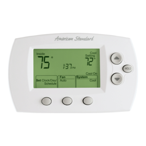
Quick reference to controls Digital display screen Battery holder Temperature buttons Press to adjust temperature settings Hold button Press to override programmed temperature control Function buttons Press to select the function displayed just above each button. (Functions change depending on the task.) Quick reference to display screen Current inside temperature Low battery warning... -
Page 15: In Case Of Difficulty
In case of difficulty If you have difficulty with your Comfort Control, please try the suggestions below. Most problems can be corrected quickly and easily. Display is blank • Check circuit breaker and reset if necessary. • Make sure power switch at heating & cooling system is on. •... -
Page 16: Accessories/Replacement Parts
91 mm H x 147 mm W x 38 mm D 6200 Troup Highway Tyler, TX 75711-9010 www.americanstandardair.com ® U.S. Registered Trademark • Patents Pending © 2008 American Standard Heating & Air Conditioning All rights reserved Pub. No. 11-HD02D11-3 01/08 69-1833—02...