
Related Manuals for Zeiss OPMI PROergo S7


Summary of Contents for Zeiss OPMI PROergo S7
- Page 1 ZEISS ® ® S7 / OPMI PROergo Instructions for Use G-30-1435-en Version 11.0 2018-11-30...
- Page 2 – S7 Centro suspension system, reference number: 000000-1254-580 Trademarks OPMI und PROergo is a trademark/are trademarks or registered trademark(s) of Carl Zeiss Meditec AG or other companies of the ZEISS Group in Germany and/or other countries. Manufacturer's details Carl Zeiss Meditec AG...
- Page 3 S7 / OPMI PROergo be prevented. Version 11.0 G-30-1435-en Page 3...
- Page 4 S7 / OPMI PROergo Version 11.0 Page 4 G-30-1435-en...
- Page 5 S7 / OPMI PROergo Summary of the section Section: Safety measures Section: Device overview Section: Preparations for use Section: Operation Section: What to do in the event of malfunctions Section: Care and maintenance Section: Device data Section: Keyword index Version 11.0 G-30-1435-en Page 5...
- Page 6 S7 / OPMI PROergo Version 11.0 Page 6 G-30-1435-en...
-
Page 7: Table Of Contents
S7 / OPMI PROergo Safety measures Safety measures Key to symbols ................. 9 Hazard symbols ..................9 Information symbols ...................9 Target group ..................10 Field of use ..................10 Intended use ....................10 Normal use ....................10 Reasonably foreseeable misuse ..............11 Liability and warranty ..............11 Notes for the operator .............. - Page 8 Safety measures S7 / OPMI PROergo Labels on S7 wall mount and on S7 Centro suspension system ....46 Additional labels on S7 wall mount ............51 Labels on the light sources of the suspension systems ......52 Labels on the wall power outlet (optional) ..........55 Version 11.0 Page 8 G-30-1435-en...
-
Page 9: Key To Symbols
S7 / OPMI PROergo Safety measures Key to symbols We would like to inform you of the safety aspects that must be observed when handling this device. This chapter contains a summary of the most important information concerning matters relevant to instrument safety. Hazard symbols The following safety information has been incorporated into the Instructions for Use. -
Page 10: Target Group
It is the duty of the device owner/operator to train and brief all operating personnel. Additional service activities are not part of these Instructions for Use. They will be performed by staff specially trained for this purpose by ZEISS. Field of use Intended use... -
Page 11: Reasonably Foreseeable Misuse
S7 / OPMI PROergo Safety measures Reasonably foreseeable misuse CAUTION Injury to the patient's eye! • The S7 / OPMI PROergo must not be used for ophthalmic procedures! • Make sure that no light enters the patient's eyes. CAUTION Live video images and recorded video sequences, video clips (cut sequences) and single images shall not be used for diagnosis purposes. -
Page 12: Notes For The Operator
• Note the symbols and labels attached to the device! (See Page 28.) • Only use original accessories or consumables approved by ZEISS. Legal regulations • Check regularly that the legal regulations applicable in your country with regard to accident prevention and work safety are being complied with. - Page 13 The system may only be transported over long distances (e.g. during Transport & Service relocation, return for repair, etc.) in its original packaging or in special return packaging. Please contact your dealer or ZEISS Service for this purpose. • This instrument is a high-grade technological product. To ensure optimum performance and safe working order, we recommend having it checked by our service representative as part of regular scheduled maintenance.
- Page 14 (see section "Care and maintenance"). • Modifications and repairs of this device or any equipment operated together with this device may only be performed by ZEISS SERVICE or other specialists authorized by Carl Zeiss. Optics and light •...
-
Page 15: Requirements For Operation
Safety measures Requirements for operation Prior to the very first use The system is installed by ZEISS Service or by a specialist designated by ZEISS. Make sure that the following requirements continue to be met for subsequent operation: The connecting components have been properly connected. The screw connections have been firmly tightened. -
Page 16: Before Every Use
Safety measures S7 / OPMI PROergo Before every use • When mounting accessory equipment, please make sure that the admissible total weight of the surgical microscope is not exceeded. (see "maximum load" label or the section "Technical data"). • Before every use, make certain to compensate for any added weight; this will enable the surgical microscope to maintain its balance in all positions of the working range. - Page 17 Never use force when trying to connect any electrical connectors (plugs, sockets). If a connection cannot be made, check to make sure the plug fits the socket. If any of the connectors are damaged, have the ZEISS service team or authorized service representative repair them.
-
Page 18: During Use
If there is a failure and you cannot get any help from the chapter "What to do in the event of malfunctions", attach a sign "Out of order" to the system and contact ZEISS service representative. • Do not pull at the light guide, power cord or any other connecting cables. -
Page 19: After Every Use
S7 / OPMI PROergo Safety measures • Constantly monitor the system during use. • Risk of crushing - mind your fingers! Fingers may be crushed in the areas marked with the "Risk of crushing" sign. Do not touch these areas while the device is being moved. After every use •... -
Page 20: Risk Of Burn Injuries Caused By High Illumination Intensity
Safety measures S7 / OPMI PROergo Risk of burn injuries caused by high illumination intensity General The xenon illumination is a light source with high intensity. If used improperly, excessive illumination intensities may lead to third-degree burns. Keep the illuminated tissue moist and make sure it is sufficiently rinsed. Carefully monitor the effect of the illumination on the tissue, particularly under the following circumstances: –... - Page 21 Recommendations Due to the large number of different factors involved and the lack of scientific publications on this topic, ZEISS cannot provide guidance on acceptable illumination intensities and exposure durations. However, the surgical microscope has several features that can help the user to reduce the risk of burn injuries: Version 11.0...
- Page 22 The area of the incision should be constantly moistened. Concluding remarks ZEISS recommends that the illumination of the surgical field be kept to the necessary minimum, for the patient's safety and for a good microscopic image.
-
Page 23: Stand Safety Equipment
S7 / OPMI PROergo Safety measures Stand safety equipment Halogen lighting system 1 Manual switching to the backup lamp The lamp housing contains a backup lamp which automatically swings into position when the first lamp fails. If this automatic function fails, you can switch on the backup lamp by pressing this button. - Page 24 Safety measures S7 / OPMI PROergo Xenon lighting system CAUTION The xenon lamp has a limited service life of 500 h! If used beyond its maximum service life, the xenon lamp may explode. • Please replace the xenon lamp in due time. •...
- Page 25 S7 / OPMI PROergo Safety measures Version 11.0 G-30-1435-en Page 25...
- Page 26 Safety measures S7 / OPMI PROergo Ceiling mount with lifting column Lifting column Selector switch for setting the optimum viewing height of the surgical microscope or for downward movement into the working position. As long as the selector switch remains in the turned position, the lifting column moves upward (2) or downward (1), depending on the switch position.
- Page 27 S7 / OPMI PROergo Safety measures Version 11.0 G-30-1435-en Page 27...
-
Page 28: Symbols And Labels On The Device
Safety measures S7 / OPMI PROergo Symbols and labels on the device NOTE Please comply with the warning labels and notices! • If you notice that any label is missing on your device or has become illegible, please contact us or one of our authorized representatives. We will provide you with replacements. - Page 29 S7 / OPMI PROergo Safety measures Version 11.0 G-30-1435-en Page 29...
- Page 30 Safety measures S7 / OPMI PROergo 9 "Filter selector" marking The illustration on the left shows the marks on the filter selector knob: 10 Labeling of zoom and focusing switches Labeling of the zoom and focusing switches on the handgrips. 11 "Focusing knob"...
-
Page 31: Labels On The Connection Panel
S7 / OPMI PROergo Safety measures Labels on the connection panel 1 "Potential equalization" label (floor stand only) Identifies the potential equalization connection for other active devices or for redundant connection to the protective ground. 2 "CAN" connector label Identifies the CAN bus connector. 3 Warning sign "Power output socket"... -
Page 32: Labels On S7 Floor Stand
Safety measures S7 / OPMI PROergo Labels on S7 floor stand 1 "Risk of crushing" warning label Fingers may be pinched between the carrier and suspension arms. Do not touch this area while moving the surgical microscope. 2 "Maximum load" warning label The maximum load on the suspension arm must not exceed 14 kg. - Page 33 S7 / OPMI PROergo Safety measures Version 11.0 G-30-1435-en Page 33...
- Page 34 This plate indicates the date of manufacture for the device (year-month). 9 Rating plate The rating label contains the following information: – Manufacturer's symbol – Manufacturer (company name) Carl Zeiss Meditec AG – Manufacturer's address Goeschwitzer Strasse 51-52 07745 Jena, Germany – Serial number –...
- Page 35 S7 / OPMI PROergo Safety measures Version 11.0 G-30-1435-en Page 35...
- Page 36 – Manufacturer (company name) – Manufacturer's contact details, i.e. phone number, fax number and email address of the local contact for the national ZEISS sales organization. XXXX XXXXXX – SIP number A unique identification number assigned to your device. 13 "Observe the Instructions for Use" label Observe the Instructions for Use.
- Page 37 S7 / OPMI PROergo Safety measures Version 11.0 G-30-1435-en Page 37...
-
Page 38: Additional Labels On S7 Floor Stand (Instrument Tray Option)
Safety measures S7 / OPMI PROergo Additional labels on S7 floor stand (instrument tray option) 1 "Maximum load on instrument tray" indicating label The maximum load of accessories on the instrument tray must not exceed 13 kg. Version 11.0 Page 38 G-30-1435-en... - Page 39 S7 / OPMI PROergo Safety measures Version 11.0 G-30-1435-en Page 39...
-
Page 40: Labels On S7 Ceiling Mount
Safety measures S7 / OPMI PROergo Labels on S7 ceiling mount 1 "Risk of crushing" warning label Fingers may be pinched between the carrier and suspension arms. Do not touch this area while moving the surgical microscope. 2 "Maximum load" warning label The maximum load on the suspension arm must not exceed 14 kg. - Page 41 S7 / OPMI PROergo Safety measures Version 11.0 G-30-1435-en Page 41...
- Page 42 – Manufacturer (company name) – Manufacturer's contact details, i.e. phone number, fax number and email address of the local contact for the national ZEISS sales organization. XXXX XXXXXX – SIP number A unique identification number assigned to your device. 11 Rating label (for S7 ceiling mount with rigid column) The rating label contains the following information: –...
- Page 43 12 Rating label (for S7 ceiling mount with lifting column) The rating label contains the following information: – Manufacturer's symbol – Manufacturer (company name) Carl Zeiss Meditec AG – Manufacturer's address Goeschwitzer Strasse 51-52 07745 Jena, Germany – Serial number –...
-
Page 44: Additional Label On S7 Ceiling Mount With Lifting Column
Safety measures S7 / OPMI PROergo Additional label on S7 ceiling mount with lifting column 1 "Lifting column operation" indicating sign Switch for moving the vertical position upward or downward. 2 Lifting column activation time This label represents the maximum permissible operating time as well as the subsequent mandatory rest phase for the lifting column and indicates the ratio between the operating time and the rest phase. - Page 45 S7 / OPMI PROergo Safety measures Version 11.0 G-30-1435-en Page 45...
-
Page 46: Labels On S7 Wall Mount And On S7 Centro Suspension System
Safety measures S7 / OPMI PROergo Labels on S7 wall mount and on S7 Centro suspension system 1 "Risk of crushing" warning label Fingers may be pinched between the carrier and suspension arms. Do not touch this area while moving the surgical microscope. 2 "Maximum load"... - Page 47 S7 / OPMI PROergo Safety measures Version 11.0 G-30-1435-en Page 47...
- Page 48 – Manufacturer (company name) – Manufacturer's contact details, i.e. phone number, fax number and email address of the local contact for the national ZEISS sales organization. XXXX XXXXXX – SIP number A unique identification number assigned to your device. 11 Rating label on wall mount with short arm The rating label contains the following information: –...
- Page 49 Safety measures 12 Rating label on wall mount with long arm The rating label contains the following information: – Manufacturer's symbol – Manufacturer (company name) Carl Zeiss Meditec AG – Manufacturer's address Goeschwitzer Strasse 51-52 07745 Jena, Germany – Serial number –...
- Page 50 S7 / OPMI PROergo 13 Rating label on S7 Centro suspension system The rating label contains the following information: – Manufacturer's symbol – Manufacturer (company name) Carl Zeiss Meditec AG – Manufacturer's address Goeschwitzer Strasse 51-52 07745 Jena, Germany – Serial number –...
-
Page 51: Additional Labels On S7 Wall Mount
S7 / OPMI PROergo Safety measures Additional labels on S7 wall mount 14 "Risk of crushing" indicating label Fingers may be pinched between the carrier and suspension arms. Do not touch this area while moving the surgical microscope. Version 11.0 G-30-1435-en Page 51... -
Page 52: Labels On The Light Sources Of The Suspension Systems
Safety measures S7 / OPMI PROergo Labels on the light sources of the suspension systems xenon light source 1 Warning sign "Not for Ophthalmology" The xenon light source may not be used for ophthalmological surgeries. Make sure that no xenon light enters the patient's eyes. 2 "CAUTION"... - Page 53 S7 / OPMI PROergo Safety measures Version 11.0 G-30-1435-en Page 53...
- Page 54 Safety measures S7 / OPMI PROergo Halogen light source 1 "Filter selector for halogen light source" This label indicates the position of the filter wheel. 2 "Instructions for Use" sign Observe the Instructions for Use or further applicable documents. Version 11.0 Page 54 G-30-1435-en...
-
Page 55: Labels On The Wall Power Outlet (Optional)
S7 / OPMI PROergo Safety measures Labels on the wall power outlet (optional) 1 Label - Cable connection for the foot control panel 2 Remote connector Identifies a connector to which devices with a maximum breaking capacity of 24V/0.5A may be connected. Version 11.0 G-30-1435-en Page 55... - Page 56 Safety measures S7 / OPMI PROergo Version 11.0 Page 56 G-30-1435-en...
- Page 57 S7 / OPMI PROergo Device overview Device overview PROergo surgical microscope on S7 suspension system ....60 Properties ....................60 System components .................62 OPMI PROergo surgical microscope ..........64 Set-up ......................64 Control elements, Displays, Connections ...........66 Binocular tubes and eyepieces ..............72 Floor stand S7 ................76 Set-up ......................76 Suspension arm ..................78 Carrier arm, stand column, stand base ............80...
- Page 58 Device overview S7 / OPMI PROergo Connector panel of S7 ceiling mount ............. 104 Connectors for the optional wall outlet (ceiling mount) ......106 Illumination system ...............108 Halogen lighting system ................. 110 Xenon lighting system ................112 Control panel and menu overview ..........116 Structure of the menus ................
- Page 59 S7 / OPMI PROergo Device overview Version 11.0 G-30-1435-en Page 59...
-
Page 60: Proergo Surgical Microscope On S7 Suspension System
Because the stand moves so smoothly, it is easy to underestimate how heavy it is. Therefore, move the stand slowly and carefully! The S7 ceiling mount with rigid column is a suspension system for ZEISS surgical microscopes. It comprises a suspension arm, a carrier arm, a ceiling column and a ceiling flange. - Page 61 The "1Chip HD camera" option provides high-resolution video equipment for your surgical microscope. ZEISS Service can also retrofit existing surgical microscopes with the "1Chip HD camera" option on request. The "TRIO 610 HD video camera" option with the TRIO 600 CCU camera control unit is a non-medical accessory for surgical microscopes.
-
Page 62: System Components
Device overview S7 / OPMI PROergo System components 1 S7 ceiling mount 2 S7 ceiling mount with lifting column 3 S7 wall mount 4 Floor stand S7 5 S7 central stand 6 OPMI PROergo surgical microscope with 180° tiltable tube and magnetic eyepieces. The overall system comprises a suspension system and a microscope. - Page 63 S7 / OPMI PROergo Device overview Version 11.0 G-30-1435-en Page 63...
-
Page 64: Opmi Proergo Surgical Microscope
Device overview S7 / OPMI PROergo OPMI PROergo surgical microscope Set-up The OPMI PROergo surgical microscope comprises the following modules: 1 Microscope body 2 Balancing system including magnetic brakes This system allows balancing of the surgical microscope. When the magnetic brakes are unlocked, the surgical microscope can be positioned almost effortlessly. - Page 65 S7 / OPMI PROergo Device overview Version 11.0 G-30-1435-en Page 65...
-
Page 66: Control Elements, Displays, Connections
Device overview S7 / OPMI PROergo Control elements, Displays, Connections 1 Friction adjustment of vertical axis Use this knob to adjust the friction of the vertical axis as required. 2 Balance setting of lateral tilt motion Use this knob to adjust the balance setting of the lateral tilt motion. 3 Friction of the lateral tilt axis Use this knob to adjust the friction of the lateral tilt axis as required. - Page 67 S7 / OPMI PROergo Device overview Version 11.0 G-30-1435-en Page 67...
- Page 68 Device overview S7 / OPMI PROergo 8 Rotating the video image (option) This knob allows you to rotate the video image, i.e. the video image can be rotated to provide better orientation for the assistant or for documentation purposes. The zero position of the knob is indicated by a clickstop.
- Page 69 S7 / OPMI PROergo Device overview Version 11.0 G-30-1435-en Page 69...
- Page 70 Device overview S7 / OPMI PROergo 14 Release buttons, freely programmable In combination with an S7 suspension system, specific functions of the suspension system can be assigned to these buttons (e.g.: focus, zoom, brightness control, still and video camera release, etc.) Configuring these buttons is described on Page 124 (Handgrip Settings menu).
- Page 71 S7 / OPMI PROergo Device overview Version 11.0 G-30-1435-en Page 71...
-
Page 72: Binocular Tubes And Eyepieces
Device overview S7 / OPMI PROergo Binocular tubes and eyepieces CAUTION Damage to the eyes due to high light radiation! Looking into a light source through a tube, an objective lens or an eyepiece may cause eye injury. • Never look into a light source or the sun with a tube, an objective lens or an eyepiece. - Page 73 S7 / OPMI PROergo Device overview Straight tube 45° inclined tube 180° tiltable tube Foldable Tube f170 f260 Version 11.0 G-30-1435-en Page 73...
- Page 74 Device overview S7 / OPMI PROergo Widefield eyepieces with magnetic coupling NOTE Eyepieces have a magnetic field! Please keep in mind the usual rules for the handling of magnets with regard to eyepieces that have been removed from the tube: •...
- Page 75 S7 / OPMI PROergo Device overview Version 11.0 G-30-1435-en Page 75...
-
Page 76: Floor Stand S7
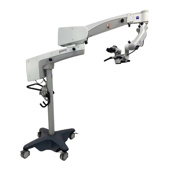
Device overview S7 / OPMI PROergo Floor stand S7 Set-up 1 Suspension arm 2 Lamp housing (either xenon or halogen illumination) 3 Support arm 4 Control panel 5 Connector panel 6 Handle 7 Cable supports (2x, on the right and left of the stand column) 8 Stand column 9 Stand base Version 11.0... - Page 77 S7 / OPMI PROergo Device overview Version 11.0 G-30-1435-en Page 77...
-
Page 78: Suspension Arm
Device overview S7 / OPMI PROergo Suspension arm 1 Lamp housing with halogen or xenon illumination The stand is equipped with an illumination system for light guides. Each lamp housing contains a backup lamp. When a halogen illumination system is used, the backup lamp will be automatically swung in if the first lamp fails. - Page 79 S7 / OPMI PROergo Device overview Version 11.0 G-30-1435-en Page 79...
-
Page 80: Carrier Arm, Stand Column, Stand Base
Device overview S7 / OPMI PROergo Carrier arm, stand column, stand base 1 Control and display panel The control and display panel permits you to control all electrical functions of the S7 floor stand and the surgical microscope. 2 Friction Knob for adjusting the friction of the carrier arm's swivel movement. - Page 81 S7 / OPMI PROergo Device overview Version 11.0 G-30-1435-en Page 81...
-
Page 82: Connector Panel Of S7 Floor Stand
Device overview S7 / OPMI PROergo Connector panel of S7 floor stand CAUTION Risk of electric shock caused by unapproved or defective accessories! Unapproved or defective accessories can cause increased leakage current! • When setting up your system, be sure to comply with the requirements of IEC 60601-1, section 16 (in some countries IEC 60601-1-1 may still be valid). - Page 83 S7 / OPMI PROergo Device overview 10 Display window for rated voltage The rated voltage displayed here must match the rated voltage of the power grid available at the installation site. You can adjust the sliding switch using a suitable tool. 11 CAN bus connector (not supported) 9 10 Version 11.0...
-
Page 84: Instrument Tray (Option)
Device overview S7 / OPMI PROergo Instrument tray (option) The S7 floor stand can be equipped or retrofitted with an instrument tray (1). In the case of retrofitting, our Service staff or an authorized person will install the instrument tray on your suspension system. The instrument tray (1) can carry a maximum of 13 kg. - Page 85 S7 / OPMI PROergo Device overview Version 11.0 G-30-1435-en Page 85...
-
Page 86: S7 Ceiling Mount
Device overview S7 / OPMI PROergo S7 ceiling mount Set-up 1 Ceiling flange 2 Stand column 3 Control panel 4 Connector panel 5 Lamp housing (either xenon or halogen illumination) 6 Suspension arm 7 Support arm Version 11.0 Page 86 G-30-1435-en... - Page 87 S7 / OPMI PROergo Device overview Version 11.0 G-30-1435-en Page 87...
-
Page 88: Support Arm And Suspension Arm
Device overview S7 / OPMI PROergo Support arm and suspension arm 1 Lamp housing with halogen or xenon illumination The stand is equipped with an illumination system for light guides. Each lamp housing contains a backup lamp. When a halogen illumination system is used, the backup lamp will be automatically swung in if the first lamp fails. - Page 89 S7 / OPMI PROergo Device overview Version 11.0 G-30-1435-en Page 89...
-
Page 90: Connector Panel Of S7 Ceiling Mount
Device overview S7 / OPMI PROergo Connector panel of S7 ceiling mount CAUTION Risk of electric shock caused by unapproved or defective accessories! Unapproved or defective accessories can cause increased leakage current! • When setting up your system, be sure to comply with the requirements of IEC 60601-1, section 16 (in some countries IEC 60601-1-1 may still be valid). - Page 91 S7 / OPMI PROergo Device overview Version 11.0 G-30-1435-en Page 91...
-
Page 92: S7 Ceiling Mount With Lifting Column
Device overview S7 / OPMI PROergo S7 ceiling mount with lifting column Set-up 1 Ceiling flange 2 Lifting column 3 Control panel 4 Connector panel 5 Lamp housing (either xenon or halogen illumination) 6 Suspension arm 7 Support arm Version 11.0 Page 92 G-30-1435-en... - Page 93 S7 / OPMI PROergo Device overview Version 11.0 G-30-1435-en Page 93...
-
Page 94: Ceiling Flange With Lifting Column
Device overview S7 / OPMI PROergo Ceiling flange with lifting column 1 Lifting column 2 Selector switch for setting the optimum viewing height of the surgical microscope or for downward movement into the working position. As long as you hold the selector switch in the turned position, the lifting column moves downward (3) or upward (4), depending on the switch position. - Page 95 S7 / OPMI PROergo Device overview Version 11.0 G-30-1435-en Page 95...
-
Page 96: Support Arm And Suspension Arm
Device overview S7 / OPMI PROergo Support arm and suspension arm 1 Lamp housing with halogen or xenon illumination The stand is equipped with an illumination system for light guides. Each lamp housing contains a backup lamp. When a halogen illumination system is used, the backup lamp will be automatically swung in if the first lamp fails. - Page 97 S7 / OPMI PROergo Device overview Version 11.0 G-30-1435-en Page 97...
-
Page 98: Connector Panel Of S7 Ceiling Mount With Lifting Column
Device overview S7 / OPMI PROergo Connector panel of S7 ceiling mount with lifting column CAUTION Risk of electric shock caused by unapproved or defective accessories! Unapproved or defective accessories can cause increased leakage current! • When setting up your system, be sure to comply with the requirements of IEC 60601-1, section 16 (in some countries IEC 60601-1-1 may still be valid). - Page 99 S7 / OPMI PROergo Device overview 8 Y/C video port (option) For S-VHS video signal output. 9 Display window for rated voltage The rated voltage displayed here must match the rated voltage of the power grid available at the installation site. You can adjust the sliding switch using a suitable tool.
-
Page 100: S7 Wall Mount And S7 Centro Suspension System
Device overview S7 / OPMI PROergo S7 wall mount and S7 Centro suspension system The functions of the S7 Centro suspension system are identical to those of the S7 wall mount. Set-up 1 Wall anchor plate (for S7 wall mount only) 2 Control panel 3 Connector panel 4 Lamp housing (either xenon or halogen illumination) - Page 101 S7 / OPMI PROergo Device overview Version 11.0 G-30-1435-en Page 101...
-
Page 102: Support Arm And Suspension Arm
Device overview S7 / OPMI PROergo Support arm and suspension arm 1 Lamp housing with halogen or xenon illumination The stand is equipped with an illumination system for light guides. Each lamp housing contains a backup lamp. When a halogen illumination system is used, the backup lamp will be automatically swung in if the first lamp fails. - Page 103 S7 / OPMI PROergo Device overview Version 11.0 G-30-1435-en Page 103...
-
Page 104: Connector Panel Of S7 Ceiling Mount
Device overview S7 / OPMI PROergo Connector panel of S7 ceiling mount CAUTION Risk of electric shock caused by unapproved or defective accessories! Unapproved or defective accessories can cause increased leakage current! • When setting up your system, be sure to comply with the requirements of IEC 60601-1, section 16 (in some countries IEC 60601-1-1 may still be valid). - Page 105 S7 / OPMI PROergo Device overview Version 11.0 G-30-1435-en Page 105...
-
Page 106: Connectors For The Optional Wall Outlet (Ceiling Mount)
Device overview S7 / OPMI PROergo Connectors for the optional wall outlet (ceiling mount) CAUTION Risk of electric shock caused by unapproved or defective accessories! Unapproved or defective accessories can cause increased leakage current! • When setting up your system, be sure to comply with the requirements of IEC 60601-1, section 16 (in some countries IEC 60601-1-1 may still be valid). - Page 107 S7 / OPMI PROergo Device overview Version 11.0 G-30-1435-en Page 107...
-
Page 108: Illumination System
Device overview S7 / OPMI PROergo Illumination system Two different types of illumination are available for the suspension system. 1 Halogen illumination The halogen light source is equipped with an illumination system for fiber illumination. The lamp housing contains a backup lamp which automatically swings into position when the first lamp fails. - Page 109 S7 / OPMI PROergo Device overview Version 11.0 G-30-1435-en Page 109...
-
Page 110: Halogen Lighting System
Device overview S7 / OPMI PROergo Halogen lighting system The illumination system has been designed for fiber illumination. The lamp housing contains a backup lamp which automatically swings into position when the first lamp fails. 1 Lamp module 2 Ventilation grid NOTE Overheating of the lamp module! If ventilation grids are covered e.g. - Page 111 S7 / OPMI PROergo Device overview Version 11.0 G-30-1435-en Page 111...
-
Page 112: Xenon Lighting System
Device overview S7 / OPMI PROergo Xenon lighting system CAUTION Risk of injury caused by xenon light in the facial area Surgery using xenon light in the facial area may seriously harm the patient's eyes. • The patient's eyes must not be exposed to xenon light. •... - Page 113 S7 / OPMI PROergo Device overview Version 11.0 G-30-1435-en Page 113...
- Page 114 Device overview S7 / OPMI PROergo When inserting a new lamp module, make sure that the knob (2) is set to "1". If the first lamp fails, switch to the second lamp in logical sequence. 3 Indicator: backup lamp is in use When the segment in knob (2) lights up, the backup lamp is in use.
- Page 115 S7 / OPMI PROergo Device overview Version 11.0 G-30-1435-en Page 115...
-
Page 116: Control Panel And Menu Overview
Device overview S7 / OPMI PROergo Control panel and menu overview The control panel consists of a graphic display (1) with control keys (3). All functions can be interactively controlled via menus. The display shows the selected functions and settings. Using control buttons (3) you can move through the menus and activate a selection field. - Page 117 S7 / OPMI PROergo Device overview Version ..Please wait ... USER 1 USER 2 NONE USER 3 NONE 50 % 50 % 300 mm 50 % 50 % 4.9 x 300 mm 20 % Standard Close 12.5 x 55 mm + 0.00 + 0.00 12.5 x...
-
Page 118: Structure Of The Menus
After you have switched on the system, the software is loaded. The growing size of the ZEISS logo with the words "Please wait..." below it indicates that this test is still in progress. The release number is displayed in the top left corner. - Page 119 S7 / OPMI PROergo Device overview Edit User Menu Three different users or applications (e.g. Endo, Paro, Cosmetic) and their profiles can be stored in the User menu. The Edit User menu allows you to enter your personal user name. When Edit icon (1) after the user name is Dr.
- Page 120 Device overview S7 / OPMI PROergo Surgery menu The Surgery menu is constantly displayed during operation. The menu includes the icons (from left to right) for the following menus: Zoom, Focus, 4.9 x 300 mm 20 % Illumination. Below: User, Options, Video and Balance. The displays below the zoom, focus, illumination and user icons show the current settings for total Standard magnification, working distance, brightness level and selected User.
- Page 121 S7 / OPMI PROergo Device overview Focus menu You can adjust the settings for the following functions in the Focus menu: Zoom Link: 50 % 300 mm The Zoom Link function lets you couple the focusing speed to the current magnification.
- Page 122 Device overview S7 / OPMI PROergo Illumination menu You can adjust the settings for the following functions in the Illumination menu: Zoom link Intensity: 50 % 50 % the illumination intensity from minimum to maximum brightness from 5% to 100% in increments of 5%. This setting can be adjusted for the xenon illumination and the halogen illumination.
- Page 123 S7 / OPMI PROergo Device overview Options menu "Options" Activate the "Options" icon and press the enter button to access the "Options" menu. The Options menu comprises the following submenus (from the top): – "Handgrip Settings" menu – "Foot Control" menu –...
- Page 124 Device overview S7 / OPMI PROergo Handgrip Settings menu This menu allows you to assign one of the listed functions to each of the four buttons (A, B, C, D) for every user or application: – Light on/off: switching the illumination on and off. –...
- Page 125 S7 / OPMI PROergo Device overview Assignment of functions: Use the ( ) arrow buttons to select the required function from the table. Use the ( ) arrow buttons to select the button required (C or D). After you have pressed the "Enter" button, a check mark ( ) indicates that the selected function has been assigned to the selected button.
- Page 126 Device overview S7 / OPMI PROergo (1), the magnetic brakes are unlocked and you can position the balanced surgical microscope. When you let go of release button (1), the magnetic brakes are locked and the surgical microscope is fixed in position again. CAUTION Injury to the patient If the system is in an extremely unbalanced state, the unit can move...
- Page 127 S7 / OPMI PROergo Device overview Option "SpeedFocus (Autofocus)" The SpeedFokus autofocus option permits you to select and automatically focus on a feature in the ROI (region of interest, measuring field) in the image of the surgical field. The SpeedFokus (autofocus) function is based on the analysis of the video image contrast: during focusing of the microscope's Varioskop optics, SpeedFokus continuously determines the video image contrast in the selected ROI.
- Page 128 Device overview S7 / OPMI PROergo The default setting for Standard User is the large ROI. You can change the size of the ROI, but the change cannot be saved for the Standard User. For specific users, the ROI size can be set and saved for each user as required. Submenu "AF - ROI Position"...
- Page 129 S7 / OPMI PROergo Device overview projects into the main beam path from the left or right, to enable the video focus to perform corrections in the right direction during the focusing process. Submenu "Advanced Settings" – This submenu is only available in systems equipped with an external video camera.
- Page 130 Device overview S7 / OPMI PROergo Balance menu The Balance menu has been designed as a user prompt and consists of six images explaining the balancing procedure. You can scroll through the Balance menu using the arrow buttons ( ). The OK button has no function.
- Page 131 S7 / OPMI PROergo Device overview Laser menu Since this surgical microscope model does not allow the attachment of a laser, the Laser menu is not used. You should therefore check that the default setting "NO NE" - No Laser is displayed in all menus (1) to ensure problem-free operation.
- Page 132 Device overview S7 / OPMI PROergo Malfunctions (Error message menu) This window appears on your display when a malfunction or incorrect operation has occurred. At the same time, this is also indicated by three beeps. The type of malfunction present and a code number are displayed in field (1). HR:-9005 The letters preceding the code number indicate the system component in which the malfunction has occurred:...
- Page 133 S7 / OPMI PROergo Device overview Version 11.0 G-30-1435-en Page 133...
-
Page 134: Optional Foot Control Panel
Device overview S7 / OPMI PROergo Optional foot control panel The foot control panel permits you to control various functions of a suspension system or a surgical microscope. The assignment of the functions to the buttons on the foot control panel is described in the following pages. -
Page 135: Foot Control Panel For Zoom And Focus
S7 / OPMI PROergo Device overview Foot control panel for zoom and focus 1 FOCUS : reducing the working distance 2 FOCUS : increasing the working distance 3 ZOOM : increasing the field of view, reducing magnification 4 ZOOM : reducing the field of view, increasing magnification Version 11.0 G-30-1435-en Page 135... -
Page 136: 14-Function Foot Control Panel, Wired (Fcp) And Wireless (Fcp Wl)
Device overview S7 / OPMI PROergo 14-function foot control panel, wired (FCP) and wireless (FCP WL) A retrofit kit for the 14 function foot control panel is available as an option. The prerequisite for this is that your device is equipped with the foot control panel connector socket. - Page 137 S7 / OPMI PROergo Device overview Version 11.0 G-30-1435-en Page 137...
-
Page 138: 1Chip Hd Camera (Option)
Device overview S7 / OPMI PROergo 1Chip HD camera (option) 1 1Chip HD camera (option) flanged to a beam splitter 2 CCU (Camera Control Unit) Control unit for the 1Chip HD camera Version 11.0 Page 138 G-30-1435-en... - Page 139 S7 / OPMI PROergo Preparations for use Preparations for use Attaching the equipment ..............142 Attaching the tube and eyepieces ............142 Connections, establishing ............. 144 Connecting the strain relief ..............144 Connecting the suspension system - S7 floor stand .........146 Connecting the suspension system - S7 ceiling mount with rigid column ...................148 Connecting the suspension system - S7 ceiling mount with lifting column ..................150...
- Page 140 Preparations for use S7 / OPMI PROergo Balancing the surgical microscope ..........168 Adjusting the surgical microscope ..........173 Preparing the device for sterile use ..........175 Attaching asepsis caps ................175 Attaching the drapes ................175 Relocating the S7 floor stand ............176 Version 11.0 Page 140 G-30-1435-en...
- Page 141 Please note that local legislation takes priority over the requirements of the above-mentioned standards. If you have any questions, contact your local dealer or Carl Zeiss Service. NOTE This equipment must not be modified without the manufacturer’s approval! Your devices may not be modified without the manufacturer’s approval.
-
Page 142: Attaching The Equipment
Preparations for use S7 / OPMI PROergo Attaching the equipment Attaching the tube and eyepieces CAUTION Risk of injury from the surgical microscope or its accessories falling down! • Never change modules and accessories during a surgical procedure or above the patient. •... - Page 143 S7 / OPMI PROergo Preparations for use Version 11.0 G-30-1435-en Page 143...
-
Page 144: Connections, Establishing
Preparations for use S7 / OPMI PROergo Connections, establishing Connecting the strain relief You can secure the power plug and the multipoint connector of the switching component against inadvertent loosening by installing the two cables in strain relief device (1). After you have mounted strain relief device (1), the cable must have the following length: –... - Page 145 S7 / OPMI PROergo Preparations for use 320 mm Version 11.0 G-30-1435-en Page 145...
-
Page 146: Connecting The Suspension System - S7 Floor Stand
Preparations for use S7 / OPMI PROergo Connecting the suspension system - S7 floor stand WARNING Danger! Electrical voltage! • To avoid the risk of electrical shock, this device may only be connected to a power supply network which is provided with a protective ground conductor. - Page 147 S7 / OPMI PROergo Preparations for use Version 11.0 G-30-1435-en Page 147...
-
Page 148: Connecting The Suspension System - S7 Ceiling Mount With Rigid Column
Preparations for use S7 / OPMI PROergo Connecting the suspension system - S7 ceiling mount with rigid column • Check the voltage indicator for (2). The stand is factory preset to the rated voltage of the country where it will be used. - Page 149 S7 / OPMI PROergo Preparations for use Version 11.0 G-30-1435-en Page 149...
-
Page 150: Connecting The Suspension System - S7 Ceiling Mount With Lifting Column
Preparations for use S7 / OPMI PROergo Connecting the suspension system - S7 ceiling mount with lifting column • Check the voltage indicator for (2). The stand is factory preset to the rated voltage of the country where it will be used. - Page 151 S7 / OPMI PROergo Preparations for use Version 11.0 G-30-1435-en Page 151...
-
Page 152: Connecting The Suspension System - S7 Wall Mount
Preparations for use S7 / OPMI PROergo Connecting the suspension system - S7 wall mount • Check the voltage indicator for (2). The stand is factory preset to the rated voltage of the country where it will be used. The rated voltage indicated at window (2) must correspond to the rated voltage available on the site of installation. - Page 153 S7 / OPMI PROergo Preparations for use Version 11.0 G-30-1435-en Page 153...
-
Page 154: Connecting The Video Monitor And The Medialink 100 (Option)
Preparations for use S7 / OPMI PROergo Connecting the video monitor and the MEDIALINK 100 (option) NOTE Use of video signal isolation When video signals are led out of the OR, e.g. for a conference, this may cause excessive leakage and contact currents. •... - Page 155 S7 / OPMI PROergo Preparations for use Devices with SpeedFocus S7 / OPMI Sensera with 1Chip HD camera option, (Autofocus) option for external MEDIALINK 100 option and video monitor / camera and 1Chip HD video recorder camera option Video monitor VIDEO IN Video recorder CCU of the 1Chip...
-
Page 156: 1Chip Hd Camera Option
Preparations for use S7 / OPMI PROergo 1Chip HD camera option Installing the 1Chip HD camera Please observe the "1Chip HD camera" Instructions for Use (G-30-1946). These Instructions for Use are included automatically in systems with the "1Chip HD camera" option. They contain all the additional explanations for the "1Chip HD camera"... -
Page 157: 1Chip Hd Camera With Iris Diaphragm For Video Lenses
S7 / OPMI PROergo Preparations for use 1Chip HD camera with iris diaphragm for video lenses Normally the 1Chip HD camera is located on the right side as viewed from the main eyepieces. The iris diaphragm for video lenses on the 1Chip HD camera allows you to re-equip your surgical microscope quickly. -
Page 158: Cable Connections For The 1Chip Hd Camera
Preparations for use S7 / OPMI PROergo Cable connections for the 1Chip HD camera CAUTION Risk of electric shock caused by unapproved or defective accessories! Unapproved or defective accessories can cause increased leakage current! • When setting up your system, be sure to comply with the requirements of IEC 60601-1, section 16 (in some countries IEC 60601-1-1 may still be valid). - Page 159 S7 / OPMI PROergo Preparations for use Version 11.0 G-30-1435-en Page 159...
-
Page 160: Adjusting The System - S7 Floor Stand
Preparations for use S7 / OPMI PROergo Adjusting the system - S7 floor stand Setting the suspension arm weight compensation CAUTION Risk of crushing - mind your fingers! Fingers may be crushed in the areas marked with the "Risk of crushing" label. •... - Page 161 S7 / OPMI PROergo Preparations for use • Lower the surgical microscope until it can be focused on the surgical field (according to the focal length of the lens). At the same time, ensure that there is a sufficiently safe distance between the microscope and the surgical field.
-
Page 162: Adjusting The System - Ceiling Mount, Wall Mount And S7
Preparations for use S7 / OPMI PROergo Adjusting the system - Ceiling mount, wall mount and S7 Centro suspension system Setting the suspension arm weight compensation CAUTION Risk of crushing - mind your fingers! Fingers may be crushed in the areas marked with the "Risk of crushing" label. •... - Page 163 S7 / OPMI PROergo Preparations for use • Lower the surgical microscope until it can be focused on the surgical field (according to the focal length of the lens). At the same time, ensure that there is a sufficiently safe distance between the microscope and the surgical field.
-
Page 164: Adjusting The System - S7 Ceiling Mount With Lifting Column
Preparations for use S7 / OPMI PROergo Adjusting the system - S7 ceiling mount with lifting column Set ergonomic working height CAUTION Risk of injury caused by lifting column Activating the lifting column may cause injuries. • Do not activate the lifting column during surgery. •... - Page 165 S7 / OPMI PROergo Preparations for use Version 11.0 G-30-1435-en Page 165...
-
Page 166: Setting The Suspension Arm Weight Compensation
Preparations for use S7 / OPMI PROergo Setting the suspension arm weight compensation CAUTION Risk of crushing - mind your fingers! Fingers may be crushed between the carrier and suspension arms. • Never touch the area between the suspension and carrier arms while you are performing the balancing procedure or moving the suspension arm. - Page 167 S7 / OPMI PROergo Preparations for use • Lower the surgical microscope to its lowest position again, and check the distance between the microscope and the surgical field. – The limit of downward travel is only effective in the lower part of the suspension arm's vertical movement range (starting from the arm's horizontal position).
-
Page 168: Balancing The Surgical Microscope
Preparations for use S7 / OPMI PROergo Balancing the surgical microscope NOTE Risk of injury to the patient! With an incorrectly balanced system, brake release may lead to uncontrolled movements of the suspension arm. • Use the surgical microscope in perfectly balanced condition only! •... - Page 169 S7 / OPMI PROergo Preparations for use Adjusting the friction of the lateral tilt axis • Use knob (3) to adjust the friction for the lateral tilt axis as required. Version 11.0 G-30-1435-en Page 169...
- Page 170 Preparations for use S7 / OPMI PROergo Balancing the front-to-back tilt motion NOTE Unintentional movement of the system With an incorrectly balanced system uncontrolled movements of the suspension system may occur. • If uncontrolled movements occur, move the surgical microscope, by overcoming the braking effect, into a position in which the patient is not put at risk.
- Page 171 S7 / OPMI PROergo Preparations for use Version 11.0 G-30-1435-en Page 171...
- Page 172 Preparations for use S7 / OPMI PROergo Correcting the balance of the front-to-back tilt motion After a slight change in the position of accessories (e.g. the angle of the coobservation tube) it may become necessary to correct the balance setting. –...
-
Page 173: Adjusting The Surgical Microscope
S7 / OPMI PROergo Preparations for use Adjusting the surgical microscope Notes on adjustment – To permit fast setup of the microscope, it is advisable to store the pupillary distances and prescriptions of the different users so that they can be easily preset during system preparation. - Page 174 Preparations for use S7 / OPMI PROergo • Repeat the entire procedure for the second eyepiece. The microscope is now adjusted so that a constantly sharp image is produced throughout the entire magnification range without your having to refocus after changing the magnification value. If this is not the case, repeat the procedure.
-
Page 175: Preparing The Device For Sterile Use
Attaching asepsis caps The device can be equipped with resterilizable products for sterile use. The asepsis sets available from ZEISS contain caps and handgrips which can be sterilized in autoclaves. For more detailed information about sterilization, please refer to the enclosed "Preparation of resterilizable products" manual for each Asepsis Set. -
Page 176: Relocating The S7 Floor Stand
Preparations for use S7 / OPMI PROergo Relocating the S7 floor stand CAUTION Risk of crushing - mind your fingers! Fingers may be crushed in the areas marked with the "Risk of crushing" label. • Do not touch these areas while the system is being moved or brought in its working / transport position. - Page 177 The system may be transported over long distances (e.g. during relocation, return for repair, etc.) only in its original packaging or in special return packaging. • Please contact your dealer or ZEISS Service for this purpose. Version 11.0 G-30-1435-en Page 177...
- Page 178 Preparations for use S7 / OPMI PROergo Version 11.0 Page 178 G-30-1435-en...
- Page 179 S7 / OPMI PROergo Operation Operation Checklist for S7 floor stand ............180 Checklist for wall mount, ceiling mount and S7 Centro suspension system ................ 184 Checklist for S7 ceiling mount with lifting column ....... 189 Switching the device on and off ...........194 Operating procedure ..............194 Working with the SpeedFokus (autofocus) option ........196 Version 11.0...
-
Page 180: Checklist For S7 Floor Stand
• Correct the malfunction (see "What to do in the event of malfunctions") or contact ZEISS Service. Always check the following points before surgery (without the patient!): • Make sure that there is sufficient clearance between the instrument and the accessories installed and that the protective cover (1) is removed from the objective lens. - Page 181 S7 / OPMI PROergo Operation Check that the xenon illumination is on and the green indicator lamp is lit. If the first lamp has failed and the backup lamp is in use (segment in the switching knob lights up), make sure to have a backup lamp module ready to hand as a precaution.
- Page 182 Operation S7 / OPMI PROergo Checking the functions of the magnetic brakes • Press release button (1). The magnetic brakes are active if Brakes are set to "Off" in the Surgery/ Options/Magnetic Brakes menu. Checking the functions of the knobs •...
- Page 183 S7 / OPMI PROergo Operation Balancing The suspension arm is properly balanced. If the suspension arm is properly balanced, the surgical microscope should remain immobile in all positions of the working range and should not swivel up or down. Stroke limit ...
-
Page 184: Checklist For Wall Mount, Ceiling Mount And S7 Centro Suspension System
• Correct the malfunction (see "What to do in the event of malfunctions") or contact ZEISS Service. Always check the following points before surgery (without the patient!): • Make sure that there is sufficient clearance between the instrument and the accessories installed and that the protective cover (1) is removed from the objective lens. - Page 185 S7 / OPMI PROergo Operation Check that the xenon illumination is on and the green indicator lamp is lit. If the first lamp has failed and the backup lamp is in use (segment in the switching knob lights up), make sure to have a backup lamp module ready to hand as a precaution.
- Page 186 Operation S7 / OPMI PROergo Checking the function of the handgrips Check that the handgrips are located in a position convenient for you, or one or both handgrips have been removed and replaced by the knobs supplied. Check the zoom •...
- Page 187 S7 / OPMI PROergo Operation Checking the functions of the magnetic brakes • Press release button (1). The magnetic brakes are active if Brakes are set to "Off" in the Surgery/ Options/Magnetic Brakes menu. Checking the functions of the knobs •...
- Page 188 Operation S7 / OPMI PROergo Balancing The suspension arm is properly balanced. If the suspension arm is properly balanced, the surgical microscope should remain immobile in all positions within the working range and should not swivel up or down. Stroke limit ...
-
Page 189: Checklist For S7 Ceiling Mount With Lifting Column
• Correct the malfunction (see "What to do in the event of malfunctions") or contact ZEISS Service. Always check the following points before surgery (without the patient!): • Make sure that there is sufficient clearance between the instrument and the accessories installed and that the protective cover (1) is removed from the objective lens. - Page 190 Operation S7 / OPMI PROergo Check that the xenon illumination is on and the green indicator lamp is lit. If the first lamp has failed and the backup lamp is in use (segment in the switching knob lights up), make sure to have a backup lamp module ready to hand as a precaution.
- Page 191 S7 / OPMI PROergo Operation Checking the function of the handgrips Check that the handgrips are located in a position convenient for you, or one or both handgrips have been removed and replaced by the knobs supplied. Check the zoom •...
- Page 192 Operation S7 / OPMI PROergo Checking the functions of the magnetic brakes • Press release button (1). The magnetic brakes are active if Brakes are set to "Off" in the Surgery/ Options/Magnetic Brakes menu. Checking the functions of the knobs •...
- Page 193 S7 / OPMI PROergo Operation Checking the lifting column • Check the function of the lifting column by operating the selector switch. Balancing The suspension arm is properly balanced. If the suspension arm is properly balanced, the surgical microscope should remain immobile in all positions of the working range and should not swivel up or down.
-
Page 194: Switching The Device On And Off
Operation S7 / OPMI PROergo Switching the device on and off The included power cord (floor stand only) is connected. • Observe the checklists starting on Page 180. This is how to switch the device on or off: • To switch it on, press the power switch (1) on the stand. - Page 195 S7 / OPMI PROergo Operation CAUTION Risk of burns caused by light! Changing the magnification on the foldable tube also changes the light intensity. Light can cause burn injuries. • After adjusting the magnification always check the light intensity and the illuminated-field diameter.
-
Page 196: Working With The Speedfokus (Autofocus) Option
Operation S7 / OPMI PROergo Working with the SpeedFokus (autofocus) option The SpeedFokus autofocus option permits you to select an area of special interest to you in the surgical field. SpeedFokus focuses on this selected area at the press of a button. Focusing is triggered on the buttons of the handgrip or foot control panel as configured in the Options menu. - Page 197 S7 / OPMI PROergo What to do in the event of malfunctions What to do in the event of malfunctions Failure of main functions ..............199 Failure of magnetic brakes ..............199 Failure of the SpeedFokus (Autofocus) option .........199 Failure of the motorized focusing function ..........200 Failure of the halogen lamps ..............202 Lamp failure of the xenon illumination ............204 Causes of malfunctions and remedies ...........
- Page 198 What to do in the event of malfunctions S7 / OPMI PROergo Version 11.0 Page 198 G-30-1435-en...
-
Page 199: Failure Of Main Functions
S7 / OPMI PROergo What to do in the event of malfunctions Failure of main functions WARNING Risk of injury caused by failure of main functions! If one of the main functions (focusing, zoom) is unavailable or is not functioning correctly, this may result in serious injury to the patient. •... -
Page 200: Failure Of The Motorized Focusing Function
What to do in the event of malfunctions S7 / OPMI PROergo Failure of the motorized focusing function Motor running constantly • Bring the suspension arm into its horizontal position and tighten locking knob (4) firmly. • Loosen and remove knurled nut (1). •... - Page 201 S7 / OPMI PROergo What to do in the event of malfunctions Version 11.0 G-30-1435-en Page 201...
-
Page 202: Failure Of The Halogen Lamps
What to do in the event of malfunctions S7 / OPMI PROergo Failure of the halogen lamps NOTE Overheating of the lamp module! If ventilation grids are covered e.g. by drapes, this may lead to overheating of the lamp housing and deactivation of the lamp. •... - Page 203 S7 / OPMI PROergo What to do in the event of malfunctions Version 11.0 G-30-1435-en Page 203...
-
Page 204: Lamp Failure Of The Xenon Illumination
What to do in the event of malfunctions S7 / OPMI PROergo Lamp failure of the xenon illumination CAUTION Risk of injury caused by lamp rupture! Lamp rupture (audible as a loud bang) may lead to jamming of the lamp module and/or failure of the electronics modules. - Page 205 S7 / OPMI PROergo What to do in the event of malfunctions • Turn knob (1) through 180° until it snaps in. This swings the second xenon lamp (backup lamp) into the beam path. • Push the lamp module all the way back into the lamp housing. Version 11.0 G-30-1435-en Page 205...
- Page 206 What to do in the event of malfunctions S7 / OPMI PROergo • Reset the operating hours counter to "0". Use a pointed object and press it into the recess of reset button (1). • Switch the suspension system back on again at the power switch. If the first lamp has failed and the backup lamp is in use (segment in the knob is lit), make sure to have a backup lamp module ready to hand as a precaution.
-
Page 207: Causes Of Malfunctions And Remedies
S7 / OPMI PROergo What to do in the event of malfunctions Causes of malfunctions and remedies For your safety This instrument is a high-grade technological product. To ensure optimum performance and safe working order, we recommend having it checked by our service representative as part of regular scheduled maintenance. - Page 208 What to do in the event of malfunctions S7 / OPMI PROergo Fault Possible reason Corrective measure Cross reference Surgical microscope tilts Surgical microscope not Balance surgical forward / backward or balanced or incorrectly microscope. sideward. balanced. Motion of surgical Friction adjustment knobs Loosen friction adjustment microscope too stiff.
- Page 209 S7 / OPMI PROergo What to do in the event of malfunctions Fault Possible reason Corrective measure Cross reference Insufficient surgical field Brightness level set too low. Adjust brightness on the Page 122 illumination. suspension system's display panel or using the foot control panel.
- Page 210 What to do in the event of malfunctions S7 / OPMI PROergo Fault Possible reason Corrective measure Cross reference Defective connecting cable Replace the cable. between video unit and monitor. If a video recorder is Connect CCU and monitor connected between CCU directly.
- Page 211 S7 / OPMI PROergo What to do in the event of malfunctions SpeedFokus video autofocus Fault Possible reason Corrective measure Cross reference SpeedFokus video Camera control unit (CCU) • Switch on MediLive autofocus is inoperative. switched off. controller (CCU). Monitor switched off. •...
- Page 212 What to do in the event of malfunctions S7 / OPMI PROergo Fault Possible reason Corrective measure Cross reference Focused image in Focusing of video camera • Focus the microscope surgical microscope, has not been matched to image, then the video but unfocused video focusing of surgical image.
- Page 213 S7 / OPMI PROergo Care and maintenance Care and maintenance Care of the device ................. 214 Cleaning ....................214 Sterilization ....................215 Disinfection ....................216 Device maintenance ..............217 Maintenance intervals ................217 Safety check ...................218 Changing the halogen lamp ..............220 Xenon lamp module, changing ...............222 Spare parts .....................224 Disposal ....................225 Version 11.0...
-
Page 214: Care Of The Device
Remove dust from the optical surfaces using a squeeze blower or a clean, grease-free brush. For regular cleaning of the surgical microscope’s objective lenses and eyepieces, we recommend using the optics cleaning kit available from ZEISS. For the catalog number, please see the section "Device data". Fogging of optical surfaces To keep the objective lenses from fogging, we recommend using an anti- fogging agent. -
Page 215: Sterilization
Make sure that the operating personnel have been instructed in the sterile operation of the device. Asepsis sets The asepsis sets available from ZEISS contain rubber caps and hand grips that can be sterilized in autoclaves. For more detailed information about sterilization, please refer to the enclosed "Preparation of resterilizable products"... -
Page 216: Disinfection
Care and maintenance S7 / OPMI PROergo NOTE Do not cover ventilation slots Covering the ventilation slots can cause the device to overheat, resulting in damage. • Do not cover the ventilation slots in order to ensure that the lamps are able to cool sufficiently and to avoid any loss in lamp functionality. -
Page 217: Device Maintenance
The maintenance activities that you are able to perform yourself are described below. Any other maintenance activities that is not described here in detail requires device-specific knowledge. Please contact your local ZEISS Service or authorized partner to arrange for the timely performance of these maintenance activities. Interval Maintenance tasks... -
Page 218: Safety Check
Care and maintenance S7 / OPMI PROergo Safety check WARNING Improper maintenance! Cables and plug connections may come loose and parts of the housing may become live. The user and patient may suffer an electric shock. • Make sure that the regular technical safety checks required for this system in accordance with the applicable national regulations are performed on schedule and to the stipulated extent. - Page 219 S7 / OPMI PROergo Care and maintenance Version 11.0 G-30-1435-en Page 219...
-
Page 220: Changing The Halogen Lamp
Care and maintenance S7 / OPMI PROergo Changing the halogen lamp NOTE Risk of burns caused by hot lamp! If you replace the lamp shortly after it has failed, the lamp will still be very hot. • Allow the lamp to cool down before changing it. •... - Page 221 S7 / OPMI PROergo Care and maintenance Version 11.0 G-30-1435-en Page 221...
-
Page 222: Xenon Lamp Module, Changing
Care and maintenance S7 / OPMI PROergo Xenon lamp module, changing CAUTION Risk of injury caused by lamp rupture! Lamp rupture (audible as a loud bang) may lead to jamming of the lamp module and/or failure of the electronics modules. •... - Page 223 – Pack the old lamp module (5) in the transport packaging of the new lamp module. Fill in the enclosed return card and send the old lamp module to the nearest ZEISS service representative. – Only use original the transport case (2), as it also provides explosion protection should the xenon lamps be faulty.
-
Page 224: Spare Parts
Care and maintenance S7 / OPMI PROergo Spare parts Asepsis sets Description Order number Asepsis caps 27 mm (pack of 6) 305810-9008-000 Asepsis caps 22 mm (pack of 6) 305810-9001-000 asepsis caps for 180° tiltable tube (pack of 6) 305810-9003-000 Halogen lighting system Description Order no. -
Page 225: Disposal
S7 / OPMI PROergo Care and maintenance Disposal User information on the disposal of electrical and electronic devices This symbol means that the product must not be disposed of as normal domestic waste. The correct disposal of electrical or electronic devices helps to protect the environment and to prevent potential hazards to the environment and/or human health which may occur as a result of improper handling of the devices concerned. - Page 226 Care and maintenance S7 / OPMI PROergo Version 11.0 Page 226 G-30-1435-en...
- Page 227 S7 / OPMI PROergo Device data Device data Technical data ................228 Essential performance features S7 / OPMI PROergo ........228 Surgical microscope ................228 Stands/mounts ..................230 Technical data on video equipment ............238 Ordering data ..................239 Compliance ................... 250 Environmental conditions ............. 251 Guidelines and manufacturer's declaration concerning electromagnetic compatibility ............
-
Page 228: Technical Data
Device data S7 / OPMI PROergo Technical data Essential performance features S7 / OPMI PROergo S7 / OPMI PROergo does not have any essential performance features as defined in IEC 60601-1. In lieu of testing the device's essential performance features, certain device functions defined by the manufacturer were tested. - Page 229 S7 / OPMI PROergo Device data Component Properties Fields of view 12–71 mm at a working distance of 200 mm (12.5x eyepiece) 20–119 mm at a working distance of 415 mm Focus Continuous motorized focusing via Varioskop focusing range 200 - 415 mm Note: The values shown on the display are different from the real values.
-
Page 230: Stands/Mounts
Device data S7 / OPMI PROergo Stands/mounts Electrical data (applies to all S7 stands/mounts) Component Properties Power supply Only connect the floor stand to wall outlets which are provided with a properly connected protective ground conductor. Rated Voltage (115 V): 100–125 V (230 V): 220–240 V Power consumption Floor stand:... - Page 231 S7 / OPMI PROergo Device data Xenon lighting system Fiber optic Xenon short-arc reflector lamp illumination Color temperature: approx. 5000 K Rated output: 180 W, rated voltage approx. 14.5 V, lamp current: 12 A, ignition voltage: 20 kV Backup lamp in lamp housing, manually selectable. Version 11.0 G-30-1435-en Page 231...
- Page 232 Device data S7 / OPMI PROergo Floor stand S7 Mechanics Component Properties Support arm Length: 450 mm Swivel angle: 360° Suspension arm Length: 865 mm Swivel angle: 305° Lifting range: -320 mm / +400 mm coupling Swivel angle: 350° Stand height 1730 mm Base dimensions 640 x 640 mm...
- Page 233 S7 / OPMI PROergo Device data S7 ceiling mount Mechanics Component Properties Support arm Length: 450 mm Swivel angle: 296° Suspension arm Length: 865 mm Swivel angle: 296° Lifting range: -320 mm / +400 mm coupling Swivel angle: 350° Admissible 14 kg (complete microscope equipment, max.
- Page 234 Device data S7 / OPMI PROergo S7 ceiling mount with lifting column Mechanics Component Properties Support arm Length: 450 mm Swivel angle: 296° Suspension arm Length: 865 mm Swivel angle: 296° Lifting range: -320 mm / +400 mm coupling Swivel angle: 350° Max.
- Page 235 S7 / OPMI PROergo Device data Technical data of lifting column Rated Voltage 24 V DC Current Consumption Vertical lift, total 350 mm Lifting force 2000 N Lifting speed 5.5 mm/sec Interval (operation / pause) 1 min / 9 min Version 11.0 G-30-1435-en Page 235...
- Page 236 Device data S7 / OPMI PROergo S7 wall mount Mechanics Component Properties Support arm Length: 450 mm Swivel angle: 190° Suspension arm Length: 865 mm Length: 1065 mm Swivel angle: 360° Swivel angle: 360° Lifting range: +400 mm Lifting range: +540 mm -320 m -390 mm coupling...
- Page 237 S7 / OPMI PROergo Device data S7 central stand Mechanics Component Properties Support arm Length: 450 mm Swivel angle: 190° Suspension arm Length: 1065 mm Swivel angle: 360° Lifting range: +540 mm -390 mm coupling Swivel angle: 350° Max. weight load 14 kg (complete microscope equipment, on suspension arm including accessories)
-
Page 238: Technical Data On Video Equipment
Device data S7 / OPMI PROergo Technical data on video equipment 1Chip HD camera (option) • See Instructions for Use G-30-1946 "1Chip HD Camera" TRIO 610 (Option) • See Instructions for Use G-30-1725 "TRIO 610 with CCU TRIO 600" Version 11.0 Page 238 G-30-1435-en... -
Page 239: Ordering Data
S7 / OPMI PROergo Device data Ordering data Only operate the device using the accessories recommended by ZEISS and included in the delivery package. To find the contact person responsible for orders in your country, visit: www.zeiss.com/med For authorized ZEISS partners, the contractual product configurations, accessories and spare parts apply. - Page 240 Device data S7 / OPMI PROergo Ordering data for country-specific cables for the S7 floor stand Description Order no. Europe 000000-0301-997 000000-0147-000 000000-0400-264 Switzerland 309850-9011-000 Argentina 000000-0434-527 China 000000-0475-507 Brazil 000000-0527-730 Ordering data for illumination Description Order number Halogen light source for S7 suspension systems 000000-1119-657 Illumination, xenon –...
- Page 241 S7 / OPMI PROergo Device data Description Order number 10x push-in widefield eyepieces (1x with "format" reticle) – 10x push-in widefield eyepiece 305542-0000-000 – 10x push-in widefield eyepiece with "format" reticle 000000-1023-184 12.5x widefield push-in eyepieces (1x with "focusing aid" reticle) –...
- Page 242 Device data S7 / OPMI PROergo Ordering data for angled lens Description Order number Angled lens without lateral output for documentation accessories 000000-1099-230 Angled lens without documentation port with tube dovetail – 1 angled lens without lateral output for documentation accessories 000000-1099-230 –...
- Page 243 180° tiltable tube, 6 caps per pack) 305810-9003-000 Sterile disposable drapes – OPMI Drapes sterile (Type 70, ZEISS VisionGuard drapes for the OPMI with 2 observation tubes and camera. Dimensions: 122 cm x 209 cm) pack with 5 drapes 306070-0000-000 –...
- Page 244 Device data S7 / OPMI PROergo Ordering data for SpeedFokus with external HD video camera Description Order number SpeedFokus for external camera with standard cable – Integrated MediLive video control unit/SpeedFokus 308203-9240-000 – Standard cable set, 5m external video rack 000000-1294-229 –...
- Page 245 S7 / OPMI PROergo Device data Ordering data for 1Chip HD camera option for S7 / OPMI PROergo Description Order no. 1Chip HD camera: – 1Chip HD camera for the OPMI PROergo/Sensera 301900-8200-000 – System cable DVI-D, 5 m 302681-8767-000 Beam splitter for the 1Chip HD camera: –...
- Page 246 Device data S7 / OPMI PROergo Description Order number With the "1Chip HD Camera" option for OPMI PROergo you automatically receive the "1Chip HD Camera" Instructions for Use (G-30-1946). SpeedFokus upgrade for the 1Chip HD camera – UC SpeedFokus for 1Chip HD camera on OPMI Sensera and OPMI PROergo 308203-9240-500 SpeedFokus for other external cameras...
- Page 247 S7 / OPMI PROergo Device data Video accessories for the 1Chip HD camera option Description Order no. External video recording Sony HD recorder 308203-9435-000 HD recorder – Sony HVO-500 MD HD with cables – Sony HVO-500MD HD recorder 000000-0575-031 – Adapter cable 000000-0576-774 –...
- Page 248 Device data S7 / OPMI PROergo Description Order no. Video cables – System cable DVI-D, 5m 302681-8767-000 – DVI monitor cable, 2m 308203-3020-000 – 5m S-VHS connection cable 2x 4 pin Mini DIN 000000-0300-281 – 10m S-VHS connection cable 2x 4 pin Mini DIN, sturdy and gold-plated contacts 308203-3070-000 –...
- Page 249 S7 / OPMI PROergo Device data Foot control panel Description Order number Foot control panel for zoom and focus 000000-1267-950 Upgrade kit for 14-function foot control panel, 304970-9055-000 wired (FCP) Upgrade kit for 14-function foot control panel, 304970-9060-000 wireless (FCP WL) 3 m connecting cable for 14-function foot control 304970-8735-000 panel (FCP &...
-
Page 250: Compliance
Device data S7 / OPMI PROergo Compliance Directives and standards with which the following devices are compliant: – The device complies with Medical Device Directive 93/42/EEC: Class I It is labeled with: – This device satisfies the US American and Canadian safety regulations for medical electrical devices/systems. -
Page 251: Environmental Conditions
S7 / OPMI PROergo Device data Environmental conditions For operation Feature Admissible range Temperature + 10°C ... + 40°C Relative humidity 30 % ... 75 % Air pressure 700 hPa ... 1060 hPa For transport and storage Feature Admissible range Temperature Without 1Chip HD camera: - 40°C ... -
Page 252: Guidelines And Manufacturer's Declaration Concerning Electromagnetic Compatibility
S7 / OPMI PROergo. • Only use accessories, transformers, cables and spare parts which are specified in these Instructions for Use or which are approved by ZEISS for the S7 / OPMI PROergo. Version 11.0... - Page 253 S7 / OPMI PROergo Device data WARNING Deterioration of performance! • Do not use any portable or mobile RF communication equipment or transmitters (including peripheral devices such as antenna cables or external antennas) in the proximity of the S7 / OPMI PROergo (minimum distance 30 cm).
-
Page 254: Emc - Electromagnetic Compatibility Iec 60601-1-2: 2014 (4Th Edition)
Device data S7 / OPMI PROergo EMC – Electromagnetic compatibility IEC 60601-1-2: 2014 (4th edition) Electromagnetic interference The S7 / OPMI PROergo is intended for operation in an electromagnetic environment as specified below. The customer or the user of the S7 / OPMI PROergo is responsible for ensuring that the device is operated in such an environment. -
Page 255: Electromagnetic Immunity For All Me Equipment And Systems
S7 / OPMI PROergo Device data Electromagnetic immunity for all ME equipment and systems The S7 / OPMI PROergo is intended for operation in the electromagnetic environment specified below. The customer or the user of the device S7 / OPMI PROergo is responsible for ensuring that it is operated in such an environment. -
Page 256: Electromagnetic Immunity For Me Equipment And Systems That Are Not Life-Sustaining
Device data S7 / OPMI PROergo Electromagnetic immunity for ME equipment and systems that are not life-sustaining The S7 / OPMI PROergo is intended for operation in the electromagnetic environment specified below. The customer or the user of the S7 / OPMI PROergo is responsible for ensuring that the device is operated in such an environment. -
Page 257: System Enhancements
As per IEC 60601-1-1 and IEC 60601-1, Section 16.2, this system's power outlet is a multiple electrical outlet intended for use with an ME system. Connecting electrical devices not approved by ZEISS can lead to a reduced level of safety on the ME system. - Page 258 Device data S7 / OPMI PROergo Version 11.0 Page 258 G-30-1435-en...
- Page 259 S7 / OPMI PROergo Keyword index Keyword index Numerics 1Chip HD camera option ................156 1Chip HD Camera with iris diaphragm ............157 Accessories for 1Chip HD camera option ..........247 Acoustic signals ..................132 Adjusting the eyepieces ................173 Adjusting the pupillary distance ..............173 Adjusting the surgical microscope ............173 Adjusting the system ..............160 Adjusting the system - Ceiling mount, wall mount and S7...
- Page 260 Keyword index S7 / OPMI PROergo Care ....................... 213 CCD array, size of .................. 129 CCD position ..................128 Ceiling anchor ..................15 Ceiling flange ..................86 Ceiling mount with lifting column ............26 Changing the halogen lamp ..............220 Changing the xenon lamp module ............
- Page 261 S7 / OPMI PROergo Keyword index Establishing connections .................144 Eyecups ....................74 Eyepieces, technical data ................229 Failure of magnetic brakes ..............199 Failure of main functions ................199 Fault .......................211 Filter GG475 ..................23 Filter KK 40 ..................23 Filter selector ..................110 Focal length of objective lens ..............229 Focal lengths ..................229 Focus menu ....................121 Focus start value ..................121...
- Page 262 Keyword index S7 / OPMI PROergo Intensity start value ................122 Iris diaphragm for video lenses ............... 157 Key to symbols ..................9 Labels on S7 wall mount and on S7 Centro suspension system ....46 Lamp failure ................... 202 Lamp housing ..............
- Page 263 S7 / OPMI PROergo Keyword index Options button ..................123 Options menu ..............123 Orange filter .....................68 Ordering data ..................239 OSD on/off .....................124 Photo .....................124 Pinhole diaphragm, medium-sized ............68 Pinhole diaphragm, small ................68 Potential equalization pin .............82 Power output socket ................82 Power switch ..................116 Preparations for use ................139 Prior to the very first use ................15 Protective ground conductor ..............15...
- Page 264 Keyword index S7 / OPMI PROergo Stand base ..................76 Stand column ................76 Standard profile ..................118 Stands/mounts ..................230 Start at ..................120 Start of menu ..................118 Start value, illumination intensity ............122 Steerable caster ..................80 Sterilization ....................
- Page 265 S7 / OPMI PROergo Keyword index Wall anchor plate ...................100 Weight ....................229 What to do in the event of malfunctions ..........197 Widefield eyepieces with magnetic coupling ..........74 Xenon illumination system ..............24 Y/C video port ..............82 Zero position ................28 Zoom link ..................121 Zoom Link function ................121 Zoom menu ....................120 Zoom speed ...................120...
- Page 266 Keyword index S7 / OPMI PROergo Version 11.0 Page 266 G-30-1435-en...
- Page 267 S7 / OPMI PROergo (Blank page for your notes . . .) Version 11.0 G-30-1435-en Page 267...
- Page 268 Carl Zeiss Meditec AG Fax: + 49 (0)7364 - 20 4823 Goeschwitzer Strasse 51-52 Email: info.meditec@zeiss.com 07745 Jena Internet: www.zeiss.com/med Germany...