Table of Contents
Advertisement
We advise you to read this manual carefully, which contains all the instructions for
maintaining the appliance's aesthetic and functional qualities.
For further information on the product: www.smeg.com
Contents
ORIGINAL INSTRUCTIONS
4
4
8
8
9
9
9
10
11
11
12
12
13
13
15
17
17
20
21
21
23
25
29
30
31
33
34
35
37
37
40
45
50
52
3
Advertisement
Table of Contents

Related Manuals for Smeg SUK91MFX9


Summary of Contents for Smeg SUK91MFX9
-
Page 1: Table Of Contents
5.3 Positioning 5.4 Electrical connection 5.5 Instructions for the installer ORIGINAL INSTRUCTIONS We advise you to read this manual carefully, which contains all the instructions for maintaining the appliance’s aesthetic and functional qualities. For further information on the product: www.smeg.com... -
Page 2: Instructions
Instructions 1 Instructions • Keep children under the age of 8 away from the appliance when it 1.1 General safety instructions is in use. • Cleaning and maintenance must Risk of personal injury not be carried out by • During use the appliance and its unsupervised children. - Page 3 Instructions • Do not insert pointed metal objects • Switch off the appliance (cutlery or utensils) into the slots in immediately after use. the appliance. • DO NOT MODIFY THIS • Do not pour water directly onto APPLIANCE. very hot trays. •...
- Page 4 Instructions Risk of damaging the appliance • DO NOT FOR ANY REASON USE THE APPLIANCE AS A • Do not use abrasive or corrosive SPACE HEATER. detergents (e.g. scouring • Do not spray any spray products powders, stain removers and near the oven.
- Page 5 Instructions • All pans must have smooth, flat • Do not use abrasive or corrosive bottoms. detergents (e.g. scouring powders, stain removers and • If any liquid does boil over or spill, metallic sponges) on glass parts. remove the excess from the hob. •...
-
Page 6: Manufacturer's Liability
Instructions • Have the electrical connection 1.2 Manufacturer’s liability performed by authorised The manufacturer declines all liability technical personnel. for damage to persons or property • The appliance must be connected caused by: to earth in compliance with • Use of the appliance other than electrical system safety standards. -
Page 7: Identification Plate
Instructions 1.4 Identification plate 1.6 Disposal The identification plate bears the This appliance must be technical data, serial number and disposed of separately from brand name of the appliance. Do not other waste (Directives remove the identification plate for 2002/95/EC, 2002/96/EC, any reason. -
Page 8: How To Read The User Manual
Instructions • Deliver the appliance to the 1.7 How to read the user manual appropriate recycling centre for This user manual uses the following reading electrical and electronic conventions: equipment waste, or return it to the Instructions retailer when purchasing an General information on this user equivalent product, on a one for manual, on safety and final... -
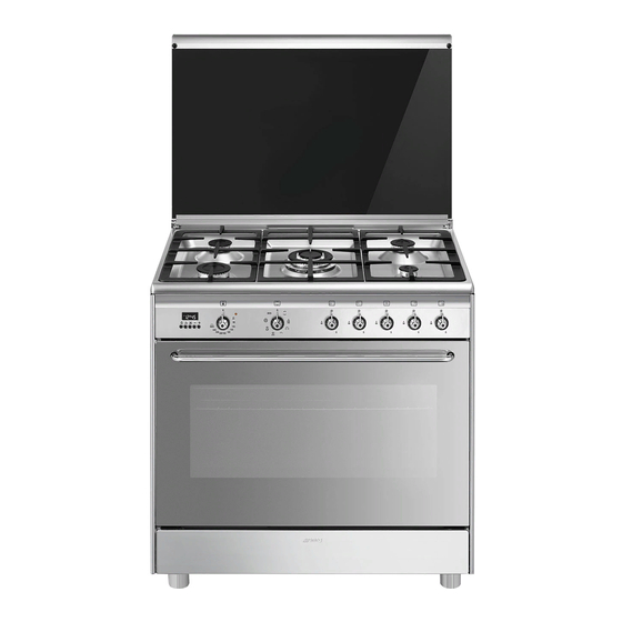
Page 9: Description
Description 2 Description 2.1 General Description 1 Upstand 6 Door 2 Cooking hob 7 Fan 3 Control panel 8 Storage compartment 4 Oven light Rack/tray support frame shelf 5 Seal... -
Page 10: Cooking Hob
Description 2.2 Cooking hob AUX = Auxiliary R = Rapid SR = Semi-rapid UR = Ultra rapid 2.3 Control panel 1 Programmer clock 3 Indicator light For displaying the current time, setting The indicator light comes on to indicate that programmed cooking operations and the the oven is heating up. -
Page 11: Other Parts
Description 5 Hob burner knobs Cooling fan Useful for lighting and adjusting the hob The fan cools the oven and comes into burners. operation during cooking. Press and turn the knobs anti-clockwise to The fan causes a steady outflow of air that exits from the rear of the appliance and the value to light the relative burners. - Page 12 Description Tray Tray rack Useful for collecting fat from foods placed To be placed over the top of the oven tray; on the rack above. for cooking foods which may drip. Deep tray Rack Useful for collecting fat from foods placed on the rack above.
-
Page 13: Use
3 Use Improper use Risk of damage to surfaces Instructions • Do not cover the bottom of the oven High temperature inside the oven cavity with aluminium or tin foil sheets. during use Danger of burns • If you wish to use greaseproof paper, place it so that it will not interfere with the •... - Page 14 Malfunctions High temperature inside the oven during use Any of the following indicate a malfunction and you should contact a service centre: Danger of fire or explosion • Yellowing of the burner plate. • Do not spray any spray products near •...
-
Page 15: To Save Energy
3.1 To save energy 3.2 Using the accessories • Preheat the appliance only if the recipe Ring reducers requires it. The ring reducers have to be placed on the • Unless differently stated on the package, hob grids. Make sure they are placed defrost frozen food before placing it in properly. - Page 16 Racks and trays Rotisserie Racks and trays have to be inserted into the 1. Insert the 4 supplied bushings in the 4 side guides until they come to a complete corner holes of the deep tray and screw stop. them onto the ring nuts with a suitable tool (such as a screwdriver).
- Page 17 3. Prepare the rotisserie rod with the food 5. Place the tray on the first runner (see using the clip forks provided. The clip “General Description”). forks can be tightened using the 6. Insert the tip of the rod in the rotisserie fastening screws.
-
Page 18: Using The Hob
8. When cooking is complete, remove the The burner may go out when the knob is released: In this case, the thermocouple has tray with the rotisserie. not heated up sufficiently. Wait a few 9. Screw on the handle provided so that moments and repeat the operation. -
Page 19: Using The Storage Compartment
3.5 Using the oven Practical tips for using the hob For better burner efficiency and to minimise Switching on the oven gas consumption, use pans with lids and of To switch on the oven: suitable size for the burner, so that the 1. - Page 20 Fan + lower element Fan assisted The combination of the fan with just The operation of the fan, combined the lower heating element allows with traditional cooking, ensures cooking to be completed more consistent cooking even with rapidly. This system is complex recipes.
-
Page 21: Cooking Advice
3.6 Cooking advice When using the ECO function, avoid opening the door during General advice cooking. • Use a fan assisted function to achieve consistent cooking at several levels. Cooking (and preheating) times • It is not possible to shorten cooking times are longer with the ECO function. - Page 22 • With the Grill function, we recommend Advice for defrosting and proving that you turn the temperature knob to the • Place frozen foods without their maximum value near the symbol packaging in a lidless container on the first shelf of the oven. optimise cooking.
-
Page 23: Digital Programmer
3.7 Digital programmer Setting the time If the time is not set, the oven will not switch on. On the first use, or after a power failure, the digits will be flashing on the appliance’s display. 1. Press the keys at the same time. - Page 24 Timed cooking 6. Press the keys at the same time to reset the programmer clock. Timed cooking is the function which allows a cooking operation to be started and then ended after It is not possible to set a cooking a specific length of time set by the time of more than 10 hours.
- Page 25 Minute minder timer 3. Use the key to set the required minutes. The minute minder timer does not stop the cooking operation but 4. Wait approx. 5 seconds without pressing rather informs the user when the set any key in order for the function to time has run out.
- Page 26 Cooking information table Runner Weight Temperature Food Function position from Time (minutes) (Kg) (°C) the bottom Lasagne 3 - 4 Static 220 - 230 45 - 50 Pasta bake 3 - 4 Static 220 - 230 45 - 50 Roast veal Turbo/Fan assisted 180 - 190 90 - 100...
-
Page 27: Cleaning And Maintenance
Cleaning and maintenance 4 Cleaning and maintenance Ordinary daily cleaning Always use specific products only that do Instructions not contain abrasives or chlorine-based acids. Improper use Pour the product onto a damp cloth and Risk of damage to surfaces wipe the surface, rinse thoroughly and dry with a soft cloth or a microfibre cloth. -
Page 28: Cleaning The Hob
Cleaning and maintenance 4.1 Cleaning the hob Igniters and thermocouples For correct operation the igniters and Cooking hob grids thermocouples must always be perfectly Remove the grids and clean them in clean. Check them frequently and clean lukewarm water and non-abrasive them with a damp cloth if necessary. -
Page 29: Cleaning The Door
Cleaning and maintenance 4.2 Cleaning the door 3. To reassemble the door, put the hinges in the relevant slots in the oven, making sure Removing the door that grooved sections A are resting For easier cleaning, the door can be completely in the slots. - Page 30 Cleaning and maintenance Removing the internal glass panes 5. Remove the intermediate glass pane by lifting it upwards. For easier cleaning the internal glass panes of the door can be removed. 1. Open the door. 2. Position the retaining clips in the holes in the hinges in order to prevent accidental closing of the door.
-
Page 31: Cleaning The Oven Cavity
Cleaning and maintenance 4.3 Cleaning the oven cavity Removing the rack/tray support frames In order to keep your oven in the best Removing the rack/tray support frames possible condition, clean it regularly after enables the sides to be cleaned more letting it cool down. -
Page 32: Vapor Clean
Cleaning and maintenance 4.4 Vapor Clean • Pour approximately 40 cc of water into the tray. Make sure it does not overflow Vapor Clean is an assisted out of the cavity. cleaning procedure which facilitates the removal of dirt. Thanks to this process, it is possible to clean the inside of the oven very easily. -
Page 33: Extraordinary Maintenance
Cleaning and maintenance 4.5 Extraordinary maintenance Vapor Clean setting 1. Turn the function knob to the symbol Installing and removing the seal To remove the seal: the temperature knob to the symbol • Unhook the clips in the 4 corners and in 2. - Page 34 Cleaning and maintenance 4. Slide out and remove the light bulb. Replacing the internal light bulb Live parts Danger of electrocution • Unplug the appliance. The oven is fitted with a 40W light bulb. Do not touch the halogen lamp directly with your fingers, but wrap 1.
-
Page 35: Installation
Installation 5 Installation Connection with a rubber hose Verify that all following conditions are met: 5.1 Gas connection • the hose is attached to the hose connector with safety clamps; Gas leak • no part of the hose is in contact with hot Danger of explosion walls (max. - Page 36 Installation Carefully screw the hose connector 3 to the Connection with a steel hose appliance’s gas connector 1 (½” thread Make the connection to the gas mains ISO 228-1), placing the seal 2 between using a continuous wall steel hose whose them.
- Page 37 Installation Connection to LPG Room ventilation Use a pressure regulator and make the The appliance should be installed in rooms connection on the gas cylinder following that have a permanent air supply in the guidelines set out in the standards in accordance with the standards in force.
-
Page 38: Adaptation To Different Types Of Gas
Installation An efficient extraction system requires 5.2 Adaptation to different types of precision planning by a specialist qualified in this area and must comply with the The appliance is preset for natural positions and clearances indicated by the gas G20 at a pressure of applicable standards. - Page 39 Installation Adjusting the minimum setting for natural Adjusting the minimum setting for LPG or town gas Tighten the screw located at the side of the Light the burner and turn it to the minimum cock rod clockwise all the way. position.
- Page 40 Installation Gas types and Countries Gas types IT GB-IE FR-BE DE RU DK 1 Natural Gas G20 20 mbar • • • • • • • • • • G20/25 20/25 mbar • 2 Natural Gas G20 25 mbar • 3 Natural Gas G25 25 mbar •...
- Page 41 Installation Burner and nozzle characteristics tables 1 Natural Gas G20 Rated heating capacity (kW) Nozzle diameter (1/100 mm) Pre-chamber (printed on nozzle) Reduced flow rate (W) 1600 2 Natural gas G20 – 25 mbar Rated heating capacity (kW) Nozzle diameter (1/100 mm) Pre-chamber (printed on nozzle) (H8) Reduced flow rate (W)
- Page 42 Installation 8 LPG G30/31 Rated heating capacity (kW) 1.75 Nozzle diameter (1/100 mm) Pre-chamber (printed on nozzle) Reduced flow rate (W) 1600 Rated flow rate G30 (g/h) Rated flow rate G31 (g/h) 9 LPG G30/G31 – 37 mbar Rated heating capacity (kW) Nozzle diameter (1/100 mm) Pre-chamber (printed on nozzle) Reduced flow rate (W)
-
Page 43: Positioning
Installation 5.3 Positioning Any wall units installed above the appliance’s worktop must be positioned at Heavy appliance least Y mm from it. If a hood is installed Crushing hazard above the hob, refer to the hood instruction manual to ensure the correct clearance is left. - Page 44 Installation Appliance overall dimensions 900 mm 600 mm B - Class 2 subclass 1 min. 150 mm (Built-in appliance) 900 - 915 mm 750 mm 450 mm 900 mm Minimum distance from side walls or other flammable material. Minimum cabinet width (=A). C - Class 2 subclass 1 (Built-in appliance) The appliance must be installed by a...
- Page 45 Installation Dimensions of the appliance: locations of Positioning and levelling gas and electric connections (mm) Heavy appliance Risk of damage to the appliance • Insert the front feet first and then the rear ones. • After making the gas and electrical connections, screw on the four feet supplied with the appliance.
- Page 46 Installation 3. Assemble the fastening bracket. Fastening to the wall The anti-tip devices must be installed in order to prevent the appliance tipping over. 1. Screw the wall fastening plate to the rear of the appliance. 4. Align the base of the hook on the fastening bracket with the base of the slot on the wall fastening plate.
- Page 47 Installation 5. Align the base of the fastening bracket 7. Move the bracket onto the wall and with the ground and tighten the screws to mark the position of the holes to be fix the measurements. drilled in the wall. 6.
-
Page 48: Electrical Connection
Installation 5.4 Electrical connection Assembling the upstand The upstand provided is an Power voltage integral part of the product. It must Danger of electrocution be fastened to the appliance prior to installation. • Have the electrical connection performed by authorised technical The upstand must always be positioned and personnel. - Page 49 Installation The appliance can work in the following Fixed connection modes: Fit the power line with an omnipolar circuit • 220-240 V 1N~ breaker in compliance with installation regulations. The circuit breaker should be located near the appliance and in an easily reachable position.
-
Page 50: Instructions For The Installer
Installation 5.5 Instructions for the installer • The plug must be accessible after installation. Do not bend or trap the power cable. • The appliance must be installed according to the installation diagrams. • Do not try to unscrew or force the threaded elbow of the fitting.