Intel P43 User Manual
Express and chipset based m/b for lga775 quad core ready intel core processor family
Hide thumbs
Also See for P43:
- Thermal/mechanical design manuallines (44 pages) ,
- User manual (46 pages)
Table of Contents
Advertisement
Quick Links
USER'S MANUAL
Of
Intel P43 Express and ICH10 Chipset
Based
M/B for LGA775 Quad Core Ready
Intel Core Processor Family
NO. G03-XBLUE-P43-F
Rev: 1.0
Release date: Sept., 2008
Trademark:
* Specifications and Information contained in this documentation are furnished for information use only, and are subject to
change at any time without notice, and should not be construed as a commitment by manufacturer.
Advertisement
Table of Contents

Related Manuals for Intel P43


Summary of Contents for Intel P43
- Page 1 USER'S MANUAL Intel P43 Express and ICH10 Chipset Based M/B for LGA775 Quad Core Ready Intel Core Processor Family NO. G03-XBLUE-P43-F Rev: 1.0 Release date: Sept., 2008 Trademark: * Specifications and Information contained in this documentation are furnished for information use only, and are subject to...
- Page 2 Environmental Protection Announcement Do not dispose this electronic device into the trash while discarding. To minimize pollution and ensure environment protection of mother earth, please recycle.
-
Page 3: Table Of Contents
TABLE OF CONTENT USER’S NOTICE........................iii MANUAL REVISION INFORMATION ................iii COOLING SOLUTIONS ......................iii CHAPTER 1 INTRODUCTION OF P43 EXPRESS AND ICH10 MOTHERBOARDS FEATURES OF MOTHERBOARD ..................1 1-1.1 SPECIAL FEATURES OF MOTHERBOARD............ 2 SPECIFICATION........................3 PERFORMANCE LIST......................4 LAYOUT DIAGRAM ......................5 CHAPTER 2 HARDWARE INSTALLATION HARDWARE INSTALLATION STEPS................ -
Page 4: User's Notice
In addition, interface materials allow effective transfers of heat from the processor to the heat sink. For optimum heat transfer, Intel recommends the use of thermal grease and mounting clips to attach the heat sink to the processor. -
Page 5: Features Of Motherboard
Introduction of Intel P43 Express and ICH10 chipset based Motherboards Features of Motherboard The P43 Express and ICH10 chipset motherboard series are based on Intel P43 Express chipset and ICH10 chipsets technology which supports the innovative 45nm and 65nm Quad-Core, Dual-Core Intel®... -
Page 6: 1-1.1 Special Features Of Motherboard
that the over-clocking may cause the failure in system reliability. This motherboard provides the guaranteed performance and meets the demands of the next generation computing. But if you insist to gain more system performance with variety possibilities of the components you choose, please be careful and make sure to read the detailed descriptions of these value added product features, please get them in the coming section. -
Page 7: Specification
∗ PCI-Express x16 slot 2pcs Expansion ∗ PCI-Express x1 slot 2pcs Slot ∗ 32-bit PCI slot x 2pcs ∗ The Intel ICH10 supports six Serial ATA ports provide 3.0 Gb/sec data Integrated transfer rate. Serial ATA2 ∗ Integrated Realtek RTL8111C PCI Gigabit LAN function. -
Page 8: Performance List
(the different Hardware & Software configuration will result in different benchmark testing results.) System Configuration CPU Type: Intel Core 2 Duo E6550; Intel Core 2 Duo E8400 Memory Type: Crucial DDR2 1066 2GB(1Gx2) Display Card: Geforce 8800GTX 768MB Hard Disk: WD WD5000AAKS SATA2 500GB OS: Microsoft Windows XP Professional 5.01.2600 Service Pack 2... -
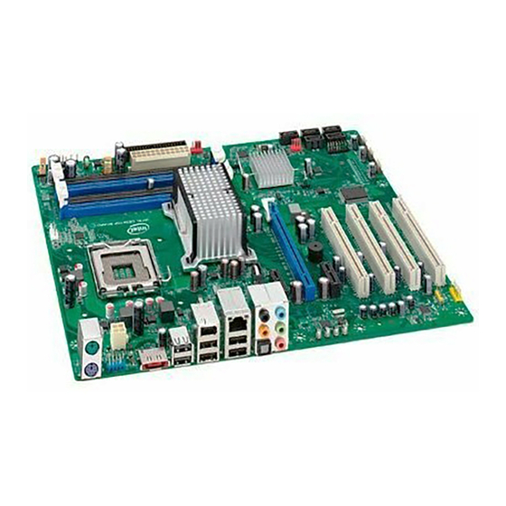
Page 9: Layout Diagram
667/800 DIMM1,2,3,4 SYS FAN1 ATX Power Connector USB Connector . LGA775 Socket R-J45 Over USB Conn. Audio Connector Intel P43 Express Floppy Connector USB/Keyboard/Mouse Chipset Power On Jumper (JP2) PCI-E2.0 x16 by 16-laneI Power on button Reset button RTL8111C Gigabit LAN... - Page 10 Jumpers Jumper Name Description Page JBAT CMOS RAM Clear 3-pin Block Keyboard and USB Power On Enabled/Disabled 3-pin Block USB Power On Enabled/Disabled 3-pin Block Connectors Connector Name Description Page ATXPWR ATX Power Connector 24-pin Block P.22 ATX12V ATX 12V Power Connector 8-pin Block P.23 CrossFire Power Connector...
-
Page 11: Chapter 2 Hardware Installation
Chapter 2 Hardware Installation WARNING! Turn off your power when adding or removing expansion cards or other system components. Failure to do so may cause severe damage to both your motherboard and expansion cards. Hardware installation Steps Before using your computer, you had better complete the following steps: 1. -
Page 12: Glossary
(2) Keyboard &Mouse &USB Power On function Enabled/Disabled: JP2 1-2 closed Keyboard &Mouse&USB 2-3 closed Keyboard & Mouse& USB Power On Disable Power On Enabled Keyboard and USB Power-On Setting (3) USB Power On function Enabled/Disabled: JP3 1-2 closed USB Power On Disable 2-3 closed USB Power On Enabled (Default) USB Power-On Setting... -
Page 13: About Intel Lga775 Cpu
2-3-2 About Intel LGA775 CPU This motherboard provides a 775-pin DIP, LGA775 Land Grid Array socket, referred to as the LGA775 socket supports Intel Pentium 4 processor in the 775 Pin package utilizes Flip-Chip Land Grid Array (FC-LGA) package technology. -
Page 14: Lga 775 Cpu Installation Guide
2-3-3 LGA 775 CPU Installation Guide Socket Preparation 1. Opening the socket: Note: Apply pressure to the corner with right hand thumb while opening/closing the load lever, otherwise lever can bounce back like a “mouse trap” and WILL cause bent contacts (when loaded) Socket Load Plate Open... - Page 15 775- Land LGA Package Insertion Lift processor package from shipping media by grasping the substrate edges ONLY. Press to remove Note: Orient processor package such that the Pin 1 triangle mark is on bottom left and both key notches are on left side Land Side Cover Handling: Remove land side cover with the opposite hand by depressing larger retention tab and peeling the cover away...
- Page 16 775- Land Package Removal Open the Load Plate/Lever with both hands: With left hand index finger and thumb to support the load plate edge, engage PnP cap with right hand thumb and peel the cap from LGA775 Socket while pressing on center of PnP cap to assist in removal.
- Page 17 7. Close the Socket Intel Reference Thermal Solution Assembly NOTE: Depending on the configuration, Thermal Solution Integration procedure could perform with M/B alone or with M/B in the Chassis. 0.150-inch backside clearance for fastener installation Fan cabled on side closest to MB header Place motherboard on support structure providing minimum 0.150-inch backside clearance...
- Page 18 Inspection • Ensure cables are not trapped or interfere fastener operation • Ensure fastener slots are pointing straight out from heatsink Fastener Cap not Fastener flush resting against spring against MB Press Down Actuate fasteners (4 Places) • While holding HS to prevent tilting, press down on fastener caps with thumb to install and lock Repeat with remaining fasteners Inspection...
- Page 19 Intel Reference Thermal Solution Disassembly Rotate fastener cap. turn to un-lock Pull up fastener cap to un-seat 12 Disconnect fan cable from motherboard header Turn fastener caps (4) counter-clock wise 90degrees to the un-locked position • A flat-bladed screwdriver may be used if required Pull up on fastener caps to unseat Manually remove HS with gentle twist motion.
- Page 20 Remove the heatsink from the socket Gently push loose thermal interface material (TIM) to center of processor (pictures 2 and 3) Remove pieces with dry cloth (picture 4) Wipe with dry, lint-free cloth to remove most of the material (picture 5) Wet another lint-free cloth with isopropyl alcohol (IPA) and wipe to clean remaining material (picture 6) Be careful to remove material from gaps between processor and load plate...
- Page 21 − Set on heatsink side or with fan down • The plastic fasteners on the heatsink can be replaced. − Use Shop Intel to order spare fasteners − http://www.shop-Intel.com • To remove a damaged fastener Note: Protective gloves are not required for this procedure −...
- Page 22 Tilt to remove Replacing Fasteners • To replace the fastener − Start with the white prong − Note the “keying” notch feature − Tilt the prong to insert into the heatsink leg. − Holding the white prong without bending it, push the black pin on from the bottom until you hear a single “click”...
-
Page 23: Installing Memory
Installing Memory This motherboard provides four 240-pin DDR2 DUAL INLINE MEMORY MODULES (DIMM) socket for DDR2 memory expansion available from minimum memory volume of 128MB to maximum memory volume of 16GB DDR SDRAM . Valid Memory Configurations for DDR2 Bank 240-Pin DIMM Total Memory Bank 0, 1 (DIMM1) -
Page 24: Expansion Card
Expansion Cards 2-5-1 Procedure For Expansion Card Installation 1. Read the documentation for your expansion card and make any necessary hardware or software setting for your expansion card such as jumpers. 2. Remove your computer’s cover and the bracket plate on the slot you intend to use. 3. -
Page 25: Pci-Express Slot
2-5-3 PCI Express Slot The P43 Express chipset Based motherboard series offer two PCI-Express x16 graphics slots that support CrossFireX Mode .One PCI-Express2.0 x16@16lane graphics slot offers 8 Gbyte/sec data transfer rate at each relative direction which get 7 times of bandwidth more than AGP8X and up to 16Gbyte/sec concurrent bandwidth at full speed, the other PCI-Express 1.0a x16@4lane graphics slots deliver up to 2Gbyte/sec data transfer rate.These... -
Page 26: Connectors, Headers
2-6 Connectors, Headers 2-6-1 Connectors Power Connector (24-pin block): ATXPWR ATX Power Supply connector: This is a new defined 24-pins connector that usually comes with ATX case. The ATX Power Supply allows using soft power on momentary switch that connect from the front panel switch to 2-pins Power On jumper pole on the motherboard. - Page 27 (2) ATX 12V Power Connector (8-pin block) : ATX12V This is a new defined 8-pin connector that usually comes with ATX Power Supply. The ATX Power Supply which fully supports LGA775 processor must including this connector for support extra 12V voltage to maintain system power consumption. Without this connector might cause system unstable because the power supply can not provide sufficient current for system.
- Page 28 Line IN (Blue) RJ-45 CEN/BASS (Black) PS/2Mouse SPDIF_OUT LineOut (Green) COM Connector Surrback (Green) PS/2 Keyboard (Orange) ) (Purple Surround (Gray) Clear CMOS MIC-IN (Pink) Button (8) Floppy drive Connector (34-pin block): FLOPPY This connector supports the provided floppy drive ribbon cable. After connecting the single plug end to motherboard, connect the two plugs at other end to the floppy drives.
-
Page 29: Headers
2-6-2 Headers (1) Line-Out/MIC Header for Front Panel (9-pin): FP_AUDIO These headers connect to Front Panel Line-out, MIC connector with cable. AUDIO Pin 1 Line-Out, MIC Headers (2) USB Port Headers (9-pin): USB2/ USB3/USB4 These headers are used for connecting the additional USB port plugs. By attaching an option USB cable, your can be provided with two additional USB plugs affixed to the back panel. - Page 30 PWRLED Pin 1 JW FP SPEAK Pin 1 Pin 1 System Case Connections (8) FAN Headers: SYSFAN1, SYSFAN2 (3-pin), CPUFAN (4-pin) These connectors support cooling fans of 350mA (4.2 Watts) or less, depending on the fan manufacturer, the wire and plug may be different. The red wire should be positive, while the black should be ground.
- Page 31 Pin 1 IR infrared module Header (11) Parallel Port Header (25-pin male): PARALLEL The onboard parallel port header is a 25-pin connector for connecting devices such as old-fashioned printer. Pin 1 PARALLEL Connector (12) SPDIF_OUT header: HDMI_SPDIF The SPDIF output is capable of providing digital audio to external speakers or compressed AC3 data to an external Dolby digital decoder.
-
Page 32: Starting Up Your Computer
2-7 Starting Up Your Computer 1. After all connection is made, close your computer case cover. 2. Be sure all the switch are off, and check that the power supply input voltage is set to proper position, usually in-put voltage is 220V∼240V or 110V∼120V depending on your country’s voltage used. -
Page 33: Chapter 3 Introducing Bios
Chapter 3 Introducing BIOS The BIOS is a program located on a Flash Memory on the motherboard. This program is a bridge between motherboard and operating system. When you start the computer, the BIOS program will gain control. The BIOS first operates an auto-diagnostic test called POST (power on self test) for all the necessary hardware, it detects the entire hardware device and configures the parameters of the hardware synchronization. -
Page 34: The Main Menu
The Main Menu Once you enter Award ® BIOS CMOS Setup Utility, the Main Menu (Figure 3-1) will appear on the screen. The Main Menu allows you to select from fourteen setup functions and two exit choices. Use arrow keys to select among the items and press <Enter> to accept or enter the sub-menu. -
Page 35: Standard Cmos Features
Save & Exit Setup Save CMOS value changes to CMOS and exit setup. Exit Without Saving Abandon all CMOS value changes and exit setup. Standard CMOS Features The items in Standard CMOS Setup Menu are divided into several categories. Each category includes no, one or more than one setup items. -
Page 36: Advanced Bios Features
Landing Zone landing zone number of sectors Sector Advanced BIOS Features Phoenix – AwardBIOS CMOS Setup Utility Advanced BIOS Features Virus Warning Disabled Item Help CPU Feature Press Enter Hard Disk Boot Priority Press Enter Menu Level > Quick Power On Self Test Enabled First Boot Device Floppy... -
Page 37: Advanced Chipset Features
During POST, BIOS will determine if the floppy disk drive installed is 40 or 80 tracks. 360K type is 40 tracks while 760K, 1.2M and 1.44M are all 80 tracks. Boot Up NumLock Status The default value is On. On (default) Keypad is numeric keys. -
Page 38: Integrated Peripherals
Selecting Enabled allows caching of the system BIOS ROM at F0000h-FFFFFh, resulting in better system performance. However, if any program writes to this memory area, a system error may result. The settings are: Enabled and Disabled. PEG/Onchip VGA Control Optional Settings are : Onchip VGA, PEG Port, Auto 。 Onchip Frame Buffer Size Optional settings are :... -
Page 39: Onboard Device Function
This setting allows you to choose IDE and AHCI. 3-7-2 Onboard Device Function Phoenix – AwardBIOS CMOS Setup Utility Onboard Device Function Onboard PCIE LAN Controller Enabled Item Help Onboard PCIE LAN BootROM Disabled High Definition Audio Enabled USB Host Controller Enabled Menu Level >>... - Page 40 Half (default). Full-duplex means that you can transmit and send information simultaneously. Half-duplex is the transmission of data in both directions , but only one direction at a time. Onboard Parallel Port There is a built-in parallel port on the on-board Super I/O chipset that Provides Standard, ECP, and EPP features.
-
Page 41: Power Management Setup
Power Management Setup The Power Management Setup allows you to configure your system to most effectively save energy saving while operating in a manner consistent with your own style of computer use. Phoenix – AwardBIOS CMOS Setup Utility Power Management Setup ACPI Function Enabled Power Management... -
Page 42: Pnp/Pci Configurations
Pressing the power button for more than 4 seconds forces the system to enter the Soft-Off state. The settings are: Delay 4 Sec, Instant-Off. Power On by Ring During Disabled, the system will ignore any incoming call from the modem. During Enabled, the system will boot up if there’s an incoming call from the modem. -
Page 43: Pc Health Status
3-10 PC Health Status This section shows the Status of you CPU, Fan, and Warning for overall system status. This is only available if there is Hardware Monitor onboard. Phoenix – AwardBIOS CMOS Setup Utility PC Health Status Shutdown Temperature Disabled CPU Thermal-Throttling Disabled... -
Page 44: Miscellaneous Control
3-11 Miscellaneous Control Phoenix – AwardBIOS CMOS Setup Utility Miscellaneous Control CPU Clock Ratio Auto Detect PCI Clock Enabled Spread Spectrum Disabled Item Help CPU Diff AMP Control 800mv CPU CLK SKEW Control NB CLK Skew Control Linear PCIEX Clock 100MHz Menu Level >... -
Page 45: Password Setting
3-12 Password Setting Phoenix – AwardBIOS CMOS Setup Utility Password Settings Item Help Set Supervisor Password Press Enter Set User Password Press Enter Menu Level > ↑↓→← Move Enter:Select +/-/PU/PD:Value F10:Save ESC:Exit F1:General Help F5:Previous Values F6:Optimized Defaults F7:Standard Defaults You can set either supervisor or user password, or both of them. -
Page 46: Chapter 4 Driver & Free Program Installation
If the menu does not appear, double-click MY COMPUTER / double-click CD-ROM drive or click START / click RUN / type X:\SETUP.EXE (assuming X is your CD-ROM drive). The Intel P43 chipset driver only of Windows 2000 & Windows XP From MAGIC INSTALL MENU you may make 8 selections: 1. -
Page 47: Inf Install Intel Inf Chipset System Driver
4-1 INF Install Intel INF Chipset System Driver 1. Click INF of the MAGIC INSTALL MENU. 2. Click NEXT when Intel Chipset Device Software Install Utility appears. 3. Click Yes to accept the license agreement and 4. Finish reading the read me information and continue the installation. -
Page 48: Sound Installalc883 Hd Audio Driver
SOUND Install ALC883 HD Audio Driver 1. Click SOUND when MAGIC INSTALL 2. Click NEXT When Realtek High Definition MENU appears Audio driver windows appear 3. Click FINISH and restart your computer 4. Manual Sound Effect Setting 5. The mixer. 6. -
Page 49: Lan Install Realtek Gigabit Ethernet Nic Driver
or later before you the HD Audio CODEC driver. Install Realtek Gigabit Ethernet NIC Driver WINDOWS 2000/XP Setup 1. Click LAN when Magic Install Menu appear. 2. Click NEXT, install REALTEK LAN and Fast Ethernet NIC Driver 3. Click install to begin the installation. 4. -
Page 50: Pc-Cillin Install Pc-Cillin 2007 Anti-Virus Program
This is the license agreement, select "I The preinstallation checkup process. Accept the terms" and Click NEXT. Click Next after you select the features you 6. Click Install after you select to install the want to install and the folder to install it. optional online services. -
Page 51: Pc-Health Install Myguard Hardware Monitor Utility
3. Click Install to begin the installation. 4. Click Finish to complete the installation. AHCI Install Intel AHCI Driver If you want to use Intel SATA AHCI mode for your system , please according to following step install driver : 1. Copy CD:\Intel3x_4x\ICH10_AHCI\f6flpy32 all file to... -
Page 52: How To Update Bios
STEP 2. Copy utility program to your boot disc. You may copy from DRIVER CD X:\FLASH\AWDFLASH.EXE or download from our web site. STEP 3. Download and make a copy of the latest BIOS for P43 series motherboard series from the web site to your boot disc. -
Page 53: Pro Magic Plus Function Introduction
Pro Magic Plus Function Introduction What’s Pro Magic Plus? Tired with reinstall OS each time when it doesn’t work? Does your computer often crash down or unable to work after installed new software? Have you had great loses and troubles because of computer problems? Still using time-consuming backup software that occupies lots of HD space? Pro Magic Plus- an instant system recovery software tailored to solve these problems for you. -
Page 54: Function Led Display
◇ Minimum of Intel 486 or above, 16MB of memory or above ◇ Minimum of 500MB free/usable space or above ◇ Support for SCSI & SATA Hard disk Pro Magic Plus only supports SCSI hard disk with Windows 2000 or OS above Notice Before Installation 1.