Table of Contents
Advertisement
Quick Links
Advertisement
Table of Contents

Related Manuals for Hyundai YL005

Summary of Contents for Hyundai YL005
- Page 1 Maintenance Manual for Collaborative Robot...
-
Page 3: About This Manual
Before using the product, read and fully understand the content of this manual. In addition, keep this manual at a handy place so that it can be read any time when necessary. This manual may be provided to customers who purchase products of Hyundai Robotics, or may be used as a material for internal training programs. - Page 4 현대로보틱스 Pressing the <Start> key will initiate the automatic execution of the sequence programmed into the robot. Cross references This provides the shortcut to the related information in the manual. Cross references will be in quotation marks, and in the bold type. ...
-
Page 5: Safety Precautions
Maintenance Manual for Collaborative Robot Safety precautions For ensuring proper product use, user safety, and for preventing property damages, make sure to read and fully understand the following precautions before using the product. Danger Impending risk: If not conformed to, operator deaths or severe injuries may occur. Danger ... - Page 6 Do not arbitrarily install, modify, disassemble or repair the product. It is prohibited for persons other than experts from Hyundai Robotics to modify the product or attach parts to the product. Product faults caused by it will void free-of-charge services and warranty services.
-
Page 7: Table Of Contents
Maintenance Manual for Collaborative Robot Contents About this manual Safety setting Programming and restarting Copyright Axis restriction devices Notation rules Movement without driving power Safety precautions Other safety precautions 1. Safety 4. Maintenance Safety requirements Checks on the collaborative robot 1.1.1 Applicable standards 4.1.1... - Page 8 현대로보틱스 6.2.3 Teach pendant Certificates Warranty _Contents...
-
Page 9: Safety
IEC 61784-3:2016 Industrial communication networks - Profiles - Part 3: Functional safety fieldbuses - General rules and profile definitions IEC 61800-3:2017 Adjustable speed electrical power drive systems - Part 3: EMC requirements and specific test methods Hyundai Robotics Safety | Safety requirements_... -
Page 10: Safety Performance
Hyundai Robotics IEC 61000-6-7:2014 Electromagnetic compatibility (EMC) - Part 6-7: Generic standards - Immunity requirements for equipment intended to perform functions in a safety-related system (functional safety) in industrial locations IEC 61326-3-1:2017 Electrical equipment for measurement, control and laboratory use. EMC requirements. Part... -
Page 11: Safety Measures
Joint-SLS, Joint Angular Speed Monitoring Joint- SLT, Joint Torque Monitoring Collision Detection TCP-SLP, TCP Position Monitoring TCP Orientation Monitoring TCP-SLS, TCP Speed Monitoring TCP Force Monitoring Momentum Monitoring Power Monitoring Hyundai Robotics Safety | Safety measures_... -
Page 12: Safety Training
( Hyundai Robotics establishes and implements plans for providing training in product installation, use, and maintenance. Product operators and workers must take the relevant training programs before handling the product. -
Page 13: Emergency Stop
On the teach pendant screen, an emergency stop massage will appear. 1.2.4.1 Emergency stop switches One emergency stop switch is installed each at the controller and the teach pendant. In case of emergency, press an emergency stop switch. Hyundai Robotics Safety | Safety measures_... - Page 14 Hyundai Robotics Figure 4 Emergency stop switches: controller (left) / teach pendant (right) 1.2.4.2 Connecting to emergency stop devices of external systems In addition to the emergency stop switches installed by default, it is possible to add external emergency stop XL devices according to site conditions and applications.
-
Page 15: Risk Assessment
In addition, safety-related functions can be composed by installing the robot at a specific location or using safety I/Os. The major categories of the risk assessment of robot integrated systems include the following: Collision severity of robots Collision probability of robots Collision avoidance probability of robots Hyundai Robotics Safety | Risk assessment_... -
Page 16: Potential Risks
Hyundai Robotics In composing robot systems, if risk factors (e.g.: use of tools unintended for collaborative robots) are not sufficiently removed by the robot’s safety functions, the necessity for additional protective devices can be identified in the risk assessment. Potential risks In the risk assessment of a robot integrated system, if the assessment result indicates that risk factors are not sufficiently removed only by the robot's safety functions, additional protective measures must be established. - Page 17 Maintenance manual for Collaborative Robot Hyundai Robotics Safety | Validity and responsibilities_...
-
Page 18: Introduction To The Product
This product may be used only for the specified intended uses. Use of this product for other purposes than the intended uses will be considered as an inappropriate behavior. Hyundai Robotics will not take responsibilities for injuries or property losses including product damages and faults caused by unintended uses of this product. -
Page 19: Product Components
Teach pendant Power connector User manual The available collaborative robot models are YL005, YL012, and YL015. This maintenance manual describes the methods for composing, installing, using, and maintaining them based on the YL012 model. Partial details including components, product parts, and methods for using may be different Note depending on collaborative robot models. -
Page 20: Part Names
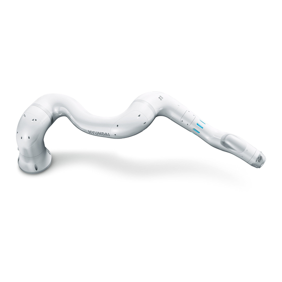
Hyundai Robotics Part names Identifying the part names of the product is useful for finding out how to install and use it. 2.3.1 Collaborative robot Arm frame R2-axis motor V-axis motor Arm pipe B-axis motor Wrist Upper frame R1-axis motor... -
Page 21: Controller
Air outlets are available only for the YL012 and the YL015 models. Note The LED lamp position varies depending on models. In the cases of the YL005 and the YL015 models, the LED lamp is on the upper frame cover. 2.3.2... -
Page 22: Teach Pendant
Hyundai Robotics Name Description Ventilation hole This is the air flow path for cooling the controller. These, mounted on the front and the rear of the controller, are used for moving Handles Emergency stop In case of emergency, it is pressed to stop the motion of the robot. -
Page 23: Nameplate
The nameplate attached on the product contains such information as robot type, manufacture number, and manufacture date. Compare it with the specifications of the purchased product. Figure 10 Nameplate of the collaborative robot Hyundai Robotics Introduction to the product | Nameplate_... - Page 24 Hyundai Robotics Figure 11 Nameplate of the controller The model names of Hyundai Robotics collaborative robots and controllers are denoted as follows: Division Information Robot code YL: Collaborative robot Payload 005: 5 kg / 012: 12 kg / 015: 15...
-
Page 25: Product Installation
Installing the product at a non-recommended place may lead to decrease in the product Caution performance and service life. Conform to the recommendations in installing and using the product. Hyundai Robotics Product installation | Environment of installation and preparation_... -
Page 26: Spaces Of Robot Systems
Maximum space: a space in which the robot can move to the maximum extent The maximum spaces of collaborative robots vary depending on models. The maximum spaces of models are as follows: YL005: 916 mm _Product installation | Environment of installation and preparation Hyundai Robotics... - Page 27 Maintenance manual for Collaborative Robot YL012: 1,305 mm YL015: 963 mm Hyundai Robotics Product installation | Environment of installation and preparation_...
- Page 28 Hyundai Robotics _Product installation | Environment of installation and preparation Hyundai Robotics...
-
Page 29: Allowable Limit Of Wrist Axis Load
The load to be applied to the tip of the wrist axis of a collaborative robot is regulated by the allowable weight, allowable load torque, and allowable moment of inertia. The allowable limits of wrist axis load of the models are as follows: Division YL005 YL012 YL015 Weight 49 N (5 kgf) maximum 117.6 N (12 kgf) maximum... - Page 30 Hyundai Robotics YL012 YL015 _Product installation | Environment of installation and preparation Hyundai Robotics...
-
Page 31: Product Installation
ISO/TS 15066 and national statutes. Caution Hyundai Robotics (or manufacturer) will not take responsibilities for accidents due to non- compliance with the applicable international standards and national statutes, or due to non- review of “Risk assessment.” 3.2.1... - Page 32 Connecting an earth cable will prevent electrostatic discharge. The information on the installation positions of YL005 and YL015 are the same with that of YL012. Tighten the bolts firmly so that they do not become loose during robot operation.
-
Page 33: Tool Connection
The flatness of the four contacting surfaces of the mounting plates should be no more than 1.0 ㎜ (±0.5 ㎜). When necessary, fill any gaps with shims. 3.2.3 Tool connection Connect a necessary tool to the collaborative robot. Check the connection port of the tool flange of the collaborative robot. Hyundai Robotics Product installation | Product installation_... - Page 34 Hyundai Robotics (even intervals). Insert the tool into the tool flange, and fixate the tool to the flange by using hex wrench bolts (M6 (12.9), four pieces) and pins (ø6). The proper tightening torque of the bolts is 127 kgf∙cm.
-
Page 35: Wiring
Connect the teach pendant connection cable of the controller to the cable connector of the teach pendant. Referring to the power connector pin map, connect one end of the power cable to the power connector. Hyundai Robotics Product installation | Product installation_... -
Page 36: Powering On
Caution Do not modify or extend cables in an arbitrary manner. Hyundai Robotics will not take responsibilities for product damages due to customer's carelessness, unskillful operation, and errors. Never arbitrarily modify, disassemble or repair the product. 3.2.5 Powering on The power to the collaborative robot is supplied through the power connector of the controller. -
Page 37: Robot Interface
Excessive force may bend or damage the pins. Do not modify or extend cables in an arbitrary manner. Hyundai Robotics will not take responsibilities for product damages due to customer's carelessness, unskillful operation, and errors. Never arbitrarily modify, disassemble or repair the product. 3.3.1 Tool flange connection point Connect the tool to the connection port of the tool flange at the tip of the collaborative robot. -
Page 38: External Device Interface
Hyundai Robotics 3.3.1.1 T4071017041-001 (TE) pin map Description Description TX + RX + TX - RX - 3.3.1.2 T41171130012-001 (TE) pin map Description Description Digital output CH0 Digital input CH2 Digital output CH1 Digital input CH3 Digital output CH2 Analog input CH0... - Page 39 3.3.2.1 Terminal block (TB1): common analog I/O signals You can connect common analog I/O signals, two at a time, to Terminal Block, TB1. For more details of signal connection, see “4.3.2.5 Connection of common digital I/O signals (TBAIO).” Hyundai Robotics Product installation | Robot interface_...
- Page 40 Hyundai Robotics Pin number Name GAIN0_N GAIN1_N GND_A GND_A Ground of Ground of GAIN0 for GAIN1 for Common analog Common analog Usage common analog common analog ground ground input input SCM TBAIO/1 SCM TBAIO/2 SCM TBAIO/3 SCM TBAIO/4 Internal connections of...
- Page 41 Collision detection, Momentum violation, Power violation, SOS violation, Joint position violation, Joint speed violation, Cartesian space violation #1 - #12 For more details of signal connection, see “4.3.2.3 Safety I/O signal connection (TBSDI, TBSDO).” Hyundai Robotics Product installation | Robot interface_...
- Page 42 Make sure to power off the product before carrying out any types of wiring, termination, and Caution electrical work. Hyundai Robotics will not take responsibilities for product damages due to customer's carelessness, unskillful operation, and errors. Never arbitrarily modify, disassemble or repair the product. ...
- Page 43 Name SIO_POW3 SIO_POW4 SDOUT0 SDOUT1 Safety signal Safety signal Safety signal Safety signal Usage input common input common output 0 output 1 (Channel 2) (Channel 2) (Channel 1) (Channel 1) Pin number Hyundai Robotics Product installation | Robot interface_...
- Page 44 Hyundai Robotics Internal connections of the controller Name SDOUT2 SDOUT3 SDOUT4 SDOUT5 SDOUT6 Safety signal Safety signal Safety signal Safety signal Safety signal Usage output 2 output 3 output 4 output 5 output 6 (Channel 1) (Channel 1) (Channel 2)
-
Page 45: Stopping Distance And Time
Extension: 33%, 66%, 100% Speed: 33%, 66%, 100% Load: 33%, 66%, 100% (YL005: 5 kg, YL012: 12 kg, YL015: 15 kg) Stop categories: STOP0, STOP1 (per IEC60204-1) 3.4.1 STOP0 At STOP0, the stopping distance and time of the models at different extension and speed values are as follows: ... -
Page 46: Stop1
Hyundai Robotics 3.4.2 STOP1 At STOP1, the stopping distance and time of the models at different axial extension and speed values are as follows: YL005 Extension: 33%, 66%, 100% Speed: 33%, 66%, 100% Stopping distance (degree) Stopping time (sec) - Page 47 Maintenance manual for Collaborative Robot YL015 Extension: 33%, 66%, 100% Speed: 33%, 66%, 100% Stopping distance (degree) Stopping time (sec) Division 100% 100% S-axis 100% H-axis 100% V-axis 100% Hyundai Robotics Product installation | Stopping distance and time_...
-
Page 48: Safety Setting
Hyundai Robotics Safety setting For the details of the safety setting of collaborative operation, see the “Safety Function Manual for Collaborative Robots.” Programming and restarting If the robot system boots up normally upon powering on, and if there is no safety issues, you can carry out programming and restarting. -
Page 49: Other Safety Precautions
For example, the automatic safeguard can be disabled in the manual mode. Before entering the automatic mode, the inputs of the automatic safeguard must be enabled. Hyundai Robotics Product installation | Other safety precautions_... -
Page 50: Maintenance
In order to use the product for a long time without anomalies, it should be checked and maintained at regular intervals. The maintenance of the robot system must be carried out by Hyundai Robotics or a service provider designated by it. -
Page 51: Check Sheet
Check all the cables, and replace any damaged cables. For checking on anomalies of power transmission devices (motors, reducers, etc.), check on abnormal noise in the automatic mode or the teaching mode. Hyundai Robotics Maintenance | Checks on the collaborative robot_... -
Page 52: Wiring Check
Hyundai Robotics 4.1.2 Wiring check The internal wiring of the collaborative robot uses cables that can withstand bending. Because disconnection or short circuit caused by damaged cables may lead to malfunction of the robot, make sure to check on the wiring at regular intervals. -
Page 53: Maintenance Of The Collaborative Robot
Replacement of the integrated driving module must be carried out by qualified experts who have taken the relevant training provided by Hyundai Robotics. In the event it is necessary to replace the integrated driving module, contact our Customer Support Team to consign the work to experts. - Page 54 Replacement of the integrated driving module must be carried out by qualified experts who have taken the relevant training provided by Hyundai Robotics. In the event it is necessary to replace the integrated driving module, contact our Customer Support Team to consign the Caution work to experts.
- Page 55 Maintenance manual for Collaborative Robot Model YL005 4.34 kg 4.34 kg 2.07 kg 2.07 kg 1.83 kg 1.83 kg YL012 6.14 kg 9.97 kg 6.14 kg 2.07 kg 2.07 kg 1.83 kg YL015 6.14 kg 9.97 kg 6.14 kg 2.07 kg 2.07 kg...
- Page 56 Hyundai Robotics Torque Model Axis Bolts Dowel pins Other parts wrenches diameter head 5XM3-6, 10XM5-18, M3, M5 3XPIN5-10 12XM5-40 10XM3-6, 12XM6-20, One-touch straight fitting M3, M6 3XPIN5-10 12XM6-45 (KQH23-00A1) 10XM3-6, 10XM5-20, M3, M5 3XPIN5-10 12XM5-40 11XM3-6, 12XM3-30, One-touch straight fitting...
- Page 57 Before correcting the encoder offset, set the operation preparation at ON, and ensure that Caution the power is connected by pressing the enabling switch of the teach pendant for two to three seconds. Hyundai Robotics Maintenance | Maintenance of the collaborative robot_...
-
Page 58: Encoder Backup Battery Replacement
Hyundai Robotics Run the robot, and check that is operates normally. 4.2.3 Encoder backup battery replacement A dedicated battery attached to the serial encoder retains the position data of each axis regardless of whether power is supplied to the controller. The battery should be replaced at two-year intervals. -
Page 59: Grease Replacement
Grease replacement requires the replacement of the integrated driving module. If grease replacement is necessary, contact our Customer Support Team. Hyundai Robotics Maintenance | Maintenance of the collaborative robot_... -
Page 60: Controller Check And Maintenance
Hyundai Robotics Controller check and maintenance Because the controller is fixated to a floor, it is not subject to mechanical damages. Therefore, you don’t need to check on it for mechanical damages over its service life. However, when the controller is repositioned or when it is impacted, you need to check its cables and connectors. -
Page 61: Safety Control Module
Data communication (exchange of torque data) with the Robot cable connection terminal CNCAN1 torque sensors (Channel 1) of the mechanical parts (CNM) CNCAN2 Robot cable connector (CNM) Data communication (exchange of torque and position Hyundai Robotics Maintenance | Controller check and maintenance_... - Page 62 Hyundai Robotics Connector Usage External connecting device data) with the torque sensors (Channel 2) and encoder (Channel 2) of the mechanical parts EtherCAT communication port Robot cable connector (CNM) EtherCAT communication port Microcomputer module (miniH6COM) Power input for driving motors of the mechanical parts...
- Page 63 Reserved signal output 4.3.2.3 Safety I/O signal connection (TBSDI, TBSDO) The safety input signals of the safety control module receives the inputs from the emergency stop switch and the safeguard through Terminal Block, TBSDI. Hyundai Robotics Maintenance | Controller check and maintenance_...
- Page 64 Hyundai Robotics Figure 19 Safety input signal connection (TBSDI) Name Usage Name Usage Safety signal input common SIO_POW1 SDIN0 Safety signal input 0 (Channel 1) (Channel 1) Safety signal input common SIO_POW1 SDIN1 Safety signal input 1 (Channel 1) (Channel 1)
- Page 65 Common digital input signals are connected through Terminal Block, TBDIO (eight signals at the maximum can be connected). In the following example, External Device is input to GDIN1, and External Device 2 is input to GDIN6. Hyundai Robotics Maintenance | Controller check and maintenance_...
- Page 66 Hyundai Robotics Figure 21 Connection of common digital input signals (TBDIO) Common digital output signals are connected through Terminal Block, TBDIO (eight at the maximum). In the following example, the load of External Device 1 is operated through output to GDOUT2, and the load of External Device 2 is operated through output to GDOUT7.
- Page 67 Ground of GAIN1 for common GAIN1_N GAIN1 Common analog input 1 analog input GND_A Common analog GND GAOUT0 Common analog output 0 GND_A Common analog GND GAOUT1 Common analog output 1 Hyundai Robotics Maintenance | Controller check and maintenance_...
-
Page 68: Power Pre-Charge Module (Ppm)
Hyundai Robotics 4.3.2.6 Information on major components The safety control module is not allowed to be subjected to maintenance because it is classified as a safety management item. Specification information on its major components other than the fuses is not provided. -
Page 69: Regenerative Discharge Module (Rdm)
It is composed of a board, regenerative discharge resistor, and a case. State display Connector inlet hole Figure 26 Outside view of the RDM Terminal block for regenerative discharge resistor connection Board (BD660) Regenerative discharge resistor Figure 27 Inside view of the RDM Hyundai Robotics Maintenance | Controller check and maintenance_... - Page 70 Hyundai Robotics 4.3.4.1 Connection and display The connector layout, usages, and connecting devices used by the RDM are as follows: Connector Usage External connecting device CNPM3 Connection of 48 V DC power line (for motor) Power pre-charge module (PPM) CNPM3...
-
Page 71: Microcomputer Module
For more details of this module, see “Operation Manual for Hi6 Controllers.” The composition of the external interface, COM ports, and power connector of the microcomputer module is as follows: Cooling fan ventilation hole Figure30 External interface of the microcomputer module Hyundai Robotics Maintenance | Controller check and maintenance_... - Page 72 Hyundai Robotics Port Usage Specification Count Display Display port LAN1, LAN2, LAN3 Wired LAN Giga LAN USB1, USB2 USB2.0 COM1, COM2 Serial communication RS-232/422/485 GPIO Digital I/O 8-bit, Dsub-9 DC IN Power input 12-24 V DC, 10A Extension slot PCIe x1, PCI...
-
Page 73: Power Supply
QUINT4-BUFFER/24DC/40, 125 (L) x 130 (W) x 56 (H) mm, 1 4.3.7 Teach pendant The teach pendant (TP600) directly manipulates the collaborative robot, and checks its state of operation and setting. Figure 34 Teach pendant Hyundai Robotics Maintenance | Controller check and maintenance_... -
Page 74: Pci Communication Card (Optional)74
Hyundai Robotics The teach pendant is connected with the microcomputer module (miniH6COM, EBC-GF53) through Ethernet communication, and has major functions as follows: Monitoring: Operating program, data of the axes, I/O signals, robot state, etc. History management: System version, operating time, error history, stoppage history, etc. - Page 75 CIFX 50E-DP-HRC PROFIBUS slave PCIe Dsub female connector, 9-pin CIFX 50E-CCIES-HRC CC-Link IE field PCIe RJ45 socket 4.3.8.1 Connect pin map The pin composition of communication connectors vary depending on PCI communication cards. Hyundai Robotics Maintenance | Controller check and maintenance_...
- Page 76 Hyundai Robotics Figure 37 Ethernet pin assignments of RJ45 sockets Signal Description Transmit data + Transmit data - Receive data + Term1 Connected to each other and terminated to PE through RC circuit (Bob Smith Termination) Term1 Receive data -...
- Page 77 +24 V DeviceNet supply voltage Figure 40 PROFIBUS interface (Dsub female connector, 9-pin Signal Description RxD/TxD-P Receive/Send Data-P respectively, connection B plug DGND Reference potential Positive supply voltage RxD/TxD-N Receive/Send Data- N respectively, connection A plug Hyundai Robotics Maintenance | Controller check and maintenance_...
-
Page 78: Moving And Storing
Hyundai Robotics Moving and storing This section describes the proper methods for moving and storing the collaborative robot. Moving method Check the weight and precautions for the collaborative robot, move it by the proper method, paying attention to safety. To move the collaborative robot manually, set it at the posture adequate for moving, and two or more workers lift it at the same time, and move it to the target location. - Page 79 Center of gravity gravity Figure 43 Moving with a crane YL005 (left) / YL015 (DN) The adequate robot posture for lifting is the same with that for the manual moving. It is recommended to set the posture of the collaborative robot as it was released from the factory, referring to “5.1.1 Recommended posture.”...
-
Page 80: Recommended Posture
Before moving the product, read and conform to the instructions specified in the maintenance manual. Hyundai Robotics will not take responsibilities for product damages due to customer's carelessness, unskillful operation, and errors. -
Page 81: Storing Method
In disposing of the robot system in whole or in part, make sure to comply with the applicable laws and regulations of the pertaining country or locality. For more details of product scrapping and disposal, contact our Customer Support Team Hyundai Robotics Moving and storing | Storing method_... - Page 82 Hyundai Robotics _Moving and storing | Disposal Hyundai Robotics...
-
Page 83: Appendix
Block diagrams 6.1.1 YL012 S-axis Material Description Quantity (manufacturer) 7112-315 BOTTOM COVER A6061-T6 7112-P01 MODULE 32 TS 7112- P02 PARALLEL PIN 5X10 7112-B01 HEX SOCEKT BOLT M4X10 12.9 7112-B02 HEX SOCEKT BOLT M5X10 12.9 Hyundai Robotics Appendix | Block diagrams_... -
Page 84: Yl012 H-Axis
Hyundai Robotics Material Description Quantity (manufacturer) 7212-441 LOWER FRAME COVER 7212-B01 HEX SOCKET BOLT M3X6 12.9 7212-B02 HEX SOCKET BOLT M5X18 12.9 6.1.2 YL012 H-axis Material Description Quantity (manufacturer) 7212-441 LOWER FRAME COVER 7212-446 UPPER FRAME COVER(1) 7212-P01 MODULE 40 TS... -
Page 85: Yl012 V-Axis
MODULE 32 TS 7212- P02 PARALLEL PIN 5X10 7212-B01 HEX SOCEKT BOLT M3X6 12.9 7212-B02 HEX SOCEKT BOLT M5X20 12.9 7212-B03 HEX SOCEKT BOLT M5X40 12.9 7312-134 ARM FRAME COVER 7312-B01 HEX SOCKET BOLT M3X6 12.9 Hyundai Robotics Appendix | Block diagrams_... -
Page 86: Yl012 R2-Axis
Hyundai Robotics 6.1.4 YL012 R2-axis Material Description Quantity (manufacturer) 7088-211 WASHER PLATE FOR M20 A6061-T6 7312-134 ARM FRAME COVER 7312-P01 MODULE 20 TS 7312-P02 PARALLEL PIN M4X15 7312-B01 HEX SOCEKT BOLT M3X6 12.9 7312-B02 HEX SOCEKT BOLT M3X30 12.9 7312-B03 HEX SOCEKT BOLT M4X25 12.9... -
Page 87: Yl012 B-Axis
HEX SOCKET BOLT M3X6 12.9 6.1.5 YL012 B-axis Material Description Quantity (manufacturer) 7088-211 WASHER PLATE FOR M20 A6061-T6 7312-306 ARM PIPE COVER 7312-P01 MODULE 20 TS 7312-P02 PARALLEL PIN M4X15 7312-B01 HEX SOCEKT BOLT M3X6 12.9 Hyundai Robotics Appendix | Block diagrams_... -
Page 88: Yl012 R1-Axis
Hyundai Robotics Material Description Quantity (manufacturer) 7312-B02 HEX SOCEKT BOLT M3X30 12.9 7312-B03 HEX SOCEKT BOLT M4X25 12.9 7412-P01 HAND GRIP MODULE 7412-B01 M3 SMALL-DIAMETER BOLT 6.1.6 YL012 R1-axis Material Description Quantity (manufacturer) 7412-P01 HAND GRIP MODULE 7412-B01 HEX SOCEKT FLAT HEAD SCREW M4X10 12.9... -
Page 89: Yl012 Tool Flange
HEX SOCEKT FLAT HEAD SCREW M4X10 12.9 6.1.8 Power connector Division Specification Order no. Manufacturer PLUG ENCLOSURE HDC 04A TWLU 1M20G 1788810000 Weidmuller INSERT HDC HA 4 MS 1498300000 Weidmuller CABLE ENTRY VG M20 - MS 68 1772220000 Weidmuller Hyundai Robotics Appendix | Block diagrams_... -
Page 90: System Specifications
Hyundai Robotics System specifications 6.2.1 Collaborative robot Division YL005 YL012 YL015 Payload 5 kg 12 kg 15 kg Structure Multi-joint type Multi-joint type Multi-joint type Degree of freedom 6-axis 6-axis 6-axis Driving type AC servo motor AC servo motor AC servo motor Rotation ±180°... -
Page 91: Controller
110 V - 220 V AC 6.2.3 Teach pendant Division Specification Weight 1186 g Dimensions 223 (W) x 291 (H) x 73 (D) mm (w/ mode switch) Ingress protection grade IP 5x Screen size 8” Cable length Hyundai Robotics Appendix | System specifications_... - Page 92 Hyundai Robotics Certificates Hyundai Robotics acquired certificates of the robot from the following official testing and certification bodies for supplying stable robot systems: Functional safety certificate Certificate image CE, NRTL certificate Certificate image Autonomous safety verification reporting certificate (KCs) ...
- Page 93 Maintenance manual for Collaborative Robot Warranty Hyundai Robotics (hereinafter, “We”), provides warranty for raw material defects and manufacturing defects of this product according to the details specified in the Warranty Statement for protecting benefits of the customers who purchase robot systems manufactured by us and sold by us or our authorized sellers. This warranty is provided only for end-users (hereinafter, “Customers”) of our robots.
- Page 94 Warranty Statement. Customer Support Representative phone number: 1670-5041 | Email: robotics@hyundai-robotics.com Working hours: Weekdays (Monday - Friday) 09:00 - 18:00 | Closed on weekends and holidays For details queries about products or services, please contact our Customer Support Team...
- Page 95 Middle Region: Song-gok-gil 161, Yeomchi-eup, Asan-si, Chungcheongnam-do Gwangju: Room 101, Building B, Pyeongdongsandan-ro 170-3, Gwangsan-gu, Gwangju-si ARS 1588-9997 | 1 Robot Sales, 2 Service Sales, 3 Purchasing Consultation, 4 Customer Support, 5 Investment Queries, 6 Recruitment and Other Queries www.hyundai-robotics.com Hyundai Robotics Warranty_...