Table of Contents
Advertisement
Quick Links
• Instructions in this Setup Guide show the PRO-4000 printer. Note that your printer may look different from these illustrations in some cases. However, the basic
operations are the same.
Caution
Before Setting Up the Printer
In order to ensure that this product is used safely, be sure to read the precautions.
-> Quick Guide (separate manual)
It is recommended that you reserve space of the following dimensions to allow you to work around the printer.
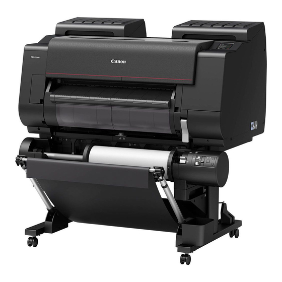
Check the completed image of the printer you purchased and make sure you have enough space to install the printer.
• The printer stand and roll unit may be options depending on the model. Care is required because the required space may differ depending on whether or not the
options are used.
Important
• The space required in front of the printer differs on how the basket supplied with the printer stand is used. This shows the installation space when used in the
position in the illustration.
PRO-2000
Installation space (W x D x H)
• When not using the stand
59.5 x 56.5 x 40.2 inches (1510 x 1434 x 1020 mm)
• When using the stand
59.5 x 66.3 x 61.5 inches (1510 x 1684 x 1560 mm)
7.9 inches
(200 mm)
23.6 inches
(600 mm)
(When not
using the stand)
23.6 inches
(600 mm)
(When using the stand)
Set up the printer using the following procedure.
*
Assemble the Stand
Install the Printer
Attach the Roll Unit
*
Attach the Basket
*
Turn On the Printer
Install the Ink Tanks
Install the Print Head
Load the Paper
• Perform Print Head Adjustment
• Connect to the Printer
• Check this also after setup is complete.
Store Accessories in the Pockets
How to Display the Online Manuals
QT6-2133-V01
XXXXXXXX
Setup Guide
Confirming the Installation Space
PRO-4000 / PRO-4000S
Installation space (W x D x H)
78.5 x 66.3 x 61.5 inches (1993 x 1684 x 1560 mm)
5.9 inches (150 mm)
3.9 inches
(100 mm)
(When not using
the stand)
7.9 inches
(200 mm)
7.9 inches
(200 mm)
3.9 inches (100 mm)
(When using the
23.6 inches
stand)
(600 mm)
Overview of Setup
* Refer to the separate
(P.3)
manual
(P.3)
* Refer to the separate
(P.4)
manual
* Refer to the separate
(P.4)
manual
(P.4)
(P.6)
(P.8)
(P.9)
(P.10 ~ 12)
© CANON INC. 2017
5.9 inches
(150 mm)
7.9 inches
(200 mm)
3.9 inches
(100 mm)
If an error message appears during setup or other problems occur,
refer to "Responding to Messages" on p.14.
• Some items are included with the printer but not described in
this manual.
Note
Keep these items in a safe place after setup because they
are used in various printing applications.
• For instructions on the included items not described in this
manual, refer to the Online Manual. ("How to Display the
Online Manuals" on p.14)
• A cable to connect the printer to a computer is not provided
with the printer.
• Windows is a trademark or registered trademark of Microsoft Corporation in the
U.S. and/or other countries.
(P.13)
RMC (Regulatory Model Code): K10468
RMC (Regulatory Model Code): K10441
(P.14)
RMC (Regulatory Model Code): K10440
RMC (Regulatory Model Code): K10439
RMC (Regulatory Model Code): K10438
1
Introductory Information
Read this manual before attempting to operate the printer.
Keep this manual in a handy location for future reference.
PRO-6000 / PRO-6000S
Installation space (W x D x H)
94.5 x 66.3 x 61.5 inches (2399 x 1684 x 1560 mm)
7.9 inches
(200 mm)
23.6 inches
(600 mm)
PRINTED IN XXXXXXXX
ENGLISH
5.9 inches
(150 mm)
7.9 inches
(200 mm)
3.9 inches
(100 mm)
Advertisement
Table of Contents

Related Manuals for Canon Image Prograf PRO-2000


Summary of Contents for Canon Image Prograf PRO-2000
- Page 1 RMC (Regulatory Model Code): K10468 RMC (Regulatory Model Code): K10441 How to Display the Online Manuals (P.14) RMC (Regulatory Model Code): K10440 RMC (Regulatory Model Code): K10439 RMC (Regulatory Model Code): K10438 QT6-2133-V01 XXXXXXXX © CANON INC. 2017 PRINTED IN XXXXXXXX...
-
Page 2: Package Contents
Package Contents ● Printer P, Q, R, S, T A. Printer I. Print head Q. M8 hex screw (x 4) (*1) B. Basket rod / Basket cloth (*1) J. Stand leg L (*1) R. M4 Hex screw for basket arm (x 4) (*1) C. -
Page 3: Assemble The Stand
Assemble the Stand • Models That Use a Stand Assemble the stand on which you will install the printer. -> Refer to "Assemble the Stand" to "Prepare to Install the Printer" in the Printer Stand Setup Guide (separate manual). • Models That Do Not Use a Stand Proceed to "Install the Printer". -
Page 4: Attach The Roll Unit
Place the printer on the stand such that the protrusion (A) for aligning Affix the printer to the stand. the position of the printer under the rear side of the printer is aligned Remove the basket rod. with the position of the black marker on the basket rod attached to Use an M4 Allen wrench to securely affix three M4 hex screws the supporting plate. - Page 5 Peel off the tape affixed to the carriage, and then pull the protective Close the top cover. material (A) towards you and remove it. Remove the protective sheet if there is one attached. Plug the power cord into the power supply connector on the back of the printer. PRO-2000 PRO-4000 / PRO-4000S / PRO-6000 / PRO-6000S Plug the power cord into the outlet.
-
Page 6: Install The Ink Tanks
Install the Ink Tanks Install the ink tanks. The PRO-2000, PRO-4000, and PRO-6000 use 12 ink tanks, and the PRO-4000S and PRO-6000S use 8 ink tanks. Instructions on ink tank installation are shown on the screen. Open Pull out the handle part (A) of the ink tank lock lever for the color of the ink tank covers as instructed. - Page 7 Lift up the ink tank lock lever once and Firmly push down the handle part of the Make sure the ink lamp lights red. then push it down. ink tank lock lever all the way in. • If the ink lamp does not light, repeat steps 2, 3, 7, and 8.
-
Page 8: Install The Print Head
Install the Print Head When the instruction to open the top Grasp the grip in the center of the print Tilt the print head lock lever towards cover appears on the screen, open the you while pressing the button in the head locking cover and open it. -
Page 9: Load The Paper
Load the Paper Load the paper for adjustment. Tap OK. Open the top cover and lift the release • Do not touch the linear scale (A), Tap Manual. lever. carriage shaft (B), or ink tube stabilizer Important (C). Touching them may cause damage. Insert the paper for adjustment between the platen (A) and paper When using the PRO-2000 without the printer stand retainer (B) in portrait orientation with the printed side of the paper... -
Page 10: Perform Print Head Adjustment And Select The Connection Method (On The Pro-2000)
Perform Print Head Adjustment and Select the Connection Method (on the PRO-2000) The paper starts feeding, and then the Once a single sheet of the adjustment Check the screen. printer automatically starts charging the pattern has finished printing, lift up the system with ink and adjusting the print release lever and remove the paper for head. - Page 11 Perform Print Head Adjustment and Select the Connection Method (on the PRO-4000, PRO-4000S, PRO-6000, and PRO-6000S) When the screen for selecting the USB connection connection method appears, tap the connection method to use. This is the method for connecting the printer to a computer using a USB cable. Only 1 printer can be connected.
-
Page 12: Connect To The Printer
Connect to the Printer The printer connection settings and software installation are performed using a computer. However, if you selected Wireless LAN connection -> Yes -> No in steps 4 to 5 on p.10 or steps 1 to 2 on p.11, configure the wireless LAN settings only using the printer. -
Page 13: Store Accessories In The Pockets
Configure Wireless LAN Settings on the Printer If you selected Wireless LAN connection -> Yes -> No in steps 4 to 5 on p.10 or steps 1 to 2 on p.11, configure the wireless LAN settings using the printer touch screen. Once the print head adjustment has Select and tap the connection method. -
Page 14: How To Display The Online Manuals
If the message appears again, write down the error code and message, turn off the printer, and contact your Canon dealer for assistance. Error Ecxxx-xxxx You may have encountered an error that cannot be...