Table of Contents
Advertisement
Quick Links
Specifications
lGeneral
Power Source:
P/PC areas:
PX area:
Power consumption:
Dimensions (W×H×D):
Mass:
lAmplifier section
RMS Output Power: Dolby Digital Mode
lTotal RMS Dolby Digital
mode Power:
At 1kHz and total harmonic of 10%
lFront:
lCenter:
lSurround:
At 100Hz and total harmonic of 10%
lActive subwoofers:
FTC Output Power: Dolby Digital Mode:
lTotal FTC Dolby Digital mode Power:
AC 120V, 60Hz
AC 110V/127V/220-
230V/240V, 50/60Hz
25 W
430×68×423 mm
(16-15/16"×2-11/16"×16-10/16")
4 kg (8.9Ibs)
1000 W
170 W/ Channel (6Ω)
260 W/ Channel (4Ω)
70 W/ Channel (4Ω)
260 W/ Channel (4Ω)
580 W
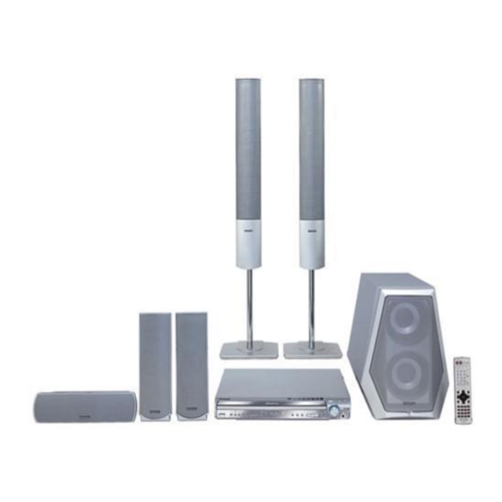
DVD Home Theater Sound System
SA-HT930P
SA-HT930PC
SA-HT930PX
Color
(S).......................Silver Type
At 120Hz-20kHz and total harmonic of 1%
lFront:
lCenter:
lSurround:
At 45Hz-120Hz and total harmonic of 1%
lSubwoofer:
lFM tuner section
Frequency Range:
Sensitivity:
S/N 26dB
Antenna Terminal:
lAM tuner section
Frequency Range:
AM Sensitivity S/N 20dB at
1000kHz:
lPhone Jack:
Terminal:
lDisc section
Discs played [8 cm (3") or 12 cm (5")]:
© 2005 Panasonic AVC Networks Singapore Pte.
Ltd. All rights reserved. Unauthorized copying and
distribution is a violation of law.
ORDER NO. MD0501009C1
A6
100 W/ Channel (6Ω)
140 W/ Channel (4Ω)
45 W/ Channel (4Ω)
150 W/ Channel (4Ω)
87.9-107.9MHz
(200kHz in step)
87.5-108.0MHz
(100kHz in step)
2.5µV (IHF)
2.2µV
75Ω (non balance)
520-1710kHz (10kHz in step)
560µV/m
Stereo 3.5 mm (1/8") jack
Advertisement
Table of Contents

Related Manuals for Panasonic SA-HT930P


Summary of Contents for Panasonic SA-HT930P
- Page 1 Stereo 3.5 mm (1/8”) jack lTotal FTC Dolby Digital mode Power: lDisc section 580 W Discs played [8 cm (3”) or 12 cm (5”)]: © 2005 Panasonic AVC Networks Singapore Pte. Ltd. All rights reserved. Unauthorized copying and distribution is a violation of law.
- Page 2 SA-HT930P / SA-HT930PC / SA-HT930PX (1) DVD-RAM (DVD-VR compatible, JPEG formatted discs) Video system: (2) DVD-Audio Signal system: NTSC (3) DVD-Video Composite video output: 1 Vp-p (75 Ω) (4) DVD-R, DVD-RW (DVD-Video compatible) Output level: +R, +RW (Video compatible) Terminal:...
-
Page 3: Table Of Contents
SA-HT930P / SA-HT930PC / SA-HT930PX CONTENTS Page Page 1 Use of Active Subwoofer 12.1. Checking, Repair Tray Motor P.C.B and Sensor P.C.B 28 1.1. Checking Player when Active Subwoofer is not used 12.2. Checking, Repair Main P.C.B 2 Safety Precautions 12.3. -
Page 4: Use Of Active Subwoofer
SA-HT930P / SA-HT930PC / SA-HT930PX 1 Use of Active Subwoofer 1.1. Checking Player when Active Subwoofer is not used 1. This unit uses the active subwoofer to supply the power of the component, and the active subwoofer should be connected to the component to check operational conditions of the component. -
Page 5: Safety Precautions
SA-HT930P / SA-HT930PC / SA-HT930PX 2 Safety Precautions 2.1. GENERAL GUIDELINES 1. When servicing, observe the original lead dress. If a short circuit is found, replace all parts which have been overheated or damaged by the short circuit. 2. After servicing, see to it that all the protective devices such as insulation barriers, insulation papers shields are properly installed. -
Page 6: Before Repair And Adjustment (Using Active Subwoofer)
SA-HT930P / SA-HT930PC / SA-HT930PX Caution Be sure no power is applied to the chassis or circuit, and observe all other safety precautions. 8. Minimize bodily motions when handling unpackaged replacement ES devices. (Otherwise harmless motion such as the brushing together of your clothes fabric or the lifting of your foot from a carpeted floor can generate static electricity (ESD)sufficient to damage an ES device). -
Page 7: Precaution Of Laser Diode
SA-HT930P / SA-HT930PC / SA-HT930PX 6 Precaution of Laser Diode CAUTION: This unit utilizes a class 1 laser. Invisible laser radiation is emitted from the optical pickup lens. Wavelength: 662nm(DVD)/785nm(VCD/CD). Maximum output radiation power from pickup: 100µW/VDE When the unit is turned on: 1. -
Page 8: General Description
SA-HT930P / SA-HT930PC / SA-HT930PX 8 General Description 8.1. Operating instructions TUNING H.BASS OPEN/CLOSE Standby/on indicator PROGRESSIVE DISC EXCHANGE CD MODE DISC SKIP INPUT SELECTOR Remote control Direct select button/indicators signal sensor TUNE MODE FM MODE PHONES VOLUME MEMORY SYSTEM... -
Page 9: Disc Information
SA-HT930P / SA-HT930PC / SA-HT930PX 8.2. Disc information Discs that can be played Indication in Disc Logo Remarks these operating instructions Recorded with devices using Version 1.1 of the Video Recording Format (a unified video recording standard), such as DVD video recorders, DVD video cameras, personal computers, etc. - Page 10 SA-HT930P / SA-HT930PC / SA-HT930PX...
-
Page 11: Using Of Receiver Unit (Sh-Fx50) - Optional
SA-HT930P / SA-HT930PC / SA-HT930PX 8.3. Using of Receiver Unit (SH-FX50) - Optional · This model can be equipped with the digital transmitter and receiver to enjoy surround sound wirelessly.. 8.3.1. Below is tips on using the digital receiver... -
Page 12: About Highmat
SA-HT930P / SA-HT930PC / SA-HT930PX 8.3.2. Tips of using digital transmitter 8.4. About HighMAT 8.4.1. What’s HighMAT? Consumers worldwide are using PCs to create their own collections of music, photos and even video by burning them onto CDs. But how these collections can be experienced across different devices can be confusing to navigate, time consuming to accessfor a DVD player, and be incomplete in terms of music information available to the customer. - Page 13 SA-HT930P / SA-HT930PC / SA-HT930PX 8.4.2. Why take advantage of HighMAT? A Problem Defined:Today, when consumers create their own digital audio, video or photo collections on CD-R or other physical formats, there are numerous, inconsistent ways that devices read the data. For the consumer, the playback experience canbe...
- Page 14 SA-HT930P / SA-HT930PC / SA-HT930PX 8.4.3. Benefits of HighMAT? Conventional HighMAT Even though DVD player is CD-R/RW compatible, the inconsistent ways HighMAT compatible products play content back with consistent that various DVD players can read the music or photos files often leads interface.
- Page 15 SA-HT930P / SA-HT930PC / SA-HT930PX HighMAT is now available for CD Burning and in Leading DVD PlayersHighMAT is a new technology that is now available in leading software and consumer electronic devices to dramatically improve the digital media experience when you create homemadeCDsHighMAT delivers a simple, standardized way for PC software and consumer electronics devices to talk to each other and work better together.
- Page 16 SA-HT930P / SA-HT930PC / SA-HT930PX When you create your homemade CDs with software that supports HighMAT CD burning, and then play them back on a DVD player that supports HighMAT, you get better, easier navigation. You get folders you can access with a single click of your DVD player´s remotecontrol.
-
Page 17: Accessories
SA-HT930P / SA-HT930PC / SA-HT930PX 9 Accessories AC cord Remote control (For P, PC areas) AM loop antenna AC cord (For PX area) FM indoor antenna Antenna plug Video Cable System cable Power plug adapter... -
Page 18: Handling Precautions For Optical Pickup Unit
SA-HT930P / SA-HT930PC / SA-HT930PX 10 Handling Precautions for Optical Pickup Unit The laser diode in the optical pickup unit may brake down due to static electricity of clothes or human body. Use due caution to electrostatic breakdown when servicing and handling the laser diode. - Page 19 SA-HT930P / SA-HT930PC / SA-HT930PX...
-
Page 20: Disassembly And Main Component Replacement Procedures
SA-HT930P / SA-HT930PC / SA-HT930PX 11 Disassembly and Main Component Replacement Procedures “ATTENTION SERVICER” Some chassis components may have sharp edges. Be careful when disassembling and servicing. 1. This section describes procedures for checking the operation of the major printed circuit boards and replacing the main components. -
Page 21: Disassembling The Top Cabinet
SA-HT930P / SA-HT930PC / SA-HT930PX 11.1. Disassembling the Top Cabinet Step 1 Remove 7 screws. Step 2 Remove the top cabinet in the direction of arrow. 11.2. Disassembling the Front Panel · Follow the (Step 1) - (Step 2) of Item 11.1. -
Page 22: Disassembling The Mechanism Base Block
SA-HT930P / SA-HT930PC / SA-HT930PX 11.5. Disassembling the Main P.C.B · Follow the (Step 1) - (Step 2) of Item 11.1. 11.4. Disassembling the Mechanism · Follow the (Step 1) - (Step 6) of Item 11.2. Base Block · Follow the (Step 1) of Item 11.3. -
Page 23: Removal Of The Tray Base Guide (L) And Tray Base Guide
SA-HT930P / SA-HT930PC / SA-HT930PX 11.6. Removal of the Tray Base Guide (L) and Tray Base Guide · Follow the (Step 1) - (Step 2) of Item 11.1. · Follow the (Step 1) - (Step 4) of Item 11.2. · Follow the (Step 1) - (Step 5) of Item 11.3. -
Page 24: Removal Of The Tray Motor P.c.b. And Sensor
SA-HT930P / SA-HT930PC / SA-HT930PX Step 3 Rotate close lock gear to direction of arrow, press claw (b) and pull out close lock gear. 11.10. Removal of the Tray Motor Step 2 Flip the base mecha unit in vertical position. -
Page 25: Removal Of The Loading Motor
SA-HT930P / SA-HT930PC / SA-HT930PX push drive gear shaft up. Step 2 Remove Drive Gear (A) and Drive Gear (B). Step 3 Release the 2 claws in the direction of arrow (1), and then push the pulley pin in the direction of arrow (2). -
Page 26: Removal Of The Cam Gear & Support Piece
SA-HT930P / SA-HT930PC / SA-HT930PX 11.16. Removal of the Cam Gear & Support Piece · Follow the (Step 1) - (Step 5) of Item 11.3. Step 1 Rotate (A) in cam gear anti-clockwise. Step 2 Remove slide plate (L) & (R) and change lever as arrow shown. -
Page 27: Assembly Of Tray Base
SA-HT930P / SA-HT930PC / SA-HT930PX 11.18. Assembly of Tray Base Step 1 Rotate cam gear anti-clockwise. Align at position (C) as marking on gear with arrow. Step 2 Make sure drive gear (A) at vertical position. Step 3 Push tray base to the direction of arrow shown. -
Page 28: Service Position
SA-HT930P / SA-HT930PC / SA-HT930PX 12 Service Position Prepare service tools before proccess service position. Service Tools Loading Motor P.C.B - Main REEX0465 (11 pin) P.C.B 12.1. Checking, Repair Tray Motor P.C.B and Sensor P.C.B · Follow the (Step 1) - (Step 2) of Item 11.1. -
Page 29: Dvd-Optical Pick-Up Self-Diagnosis And Replacement Procedure
SA-HT930P / SA-HT930PC / SA-HT930PX 13 DVD-Optical Pick-up Self-Diagnosis and Replacement Procedure 13.1. Optical Pickup Breakdown Diagnosis The optical pickup self-diagnosis function and tilt adjustment check function have been included in this unit. When repairing, use the following procedure for effective Self-diagnosis and tilt adjustment.Be sure to use the self-diagnosis functionbefore replacing the optical pickup when "NO DISC"... -
Page 30: Service Mode Table
SA-HT930P / SA-HT930PC / SA-HT930PX 13.2. Service Mode Table 1 The service modes can be activated by pressing various button combination on the player and remote control unit. Player buttons Remote control unit buttons Application Note STOP Error code display (Refer to the item, “13.3. - Page 31 SA-HT930P / SA-HT930PC / SA-HT930PX Error Code Error Content Additional error explanation F890 Sending message when message is Sending message to AV task being sent to AV task F891 Message couldn’t be sent to AV task Begin sending message to AV task...
-
Page 32: Service Mode Table
SA-HT930P / SA-HT930PC / SA-HT930PX 13.4. Service mode table 2 Pressing various button combinations on the player and remote control unit can activate the service modes. - Page 33 SA-HT930P / SA-HT930PC / SA-HT930PX...
-
Page 34: Sales Demonstration Lock Function
SA-HT930P / SA-HT930PC / SA-HT930PX 13.5. Sales demonstration lock function This function prevents discs from being lost when the unit is used for sales demonstrations by disabling the disc eject function. "LOCKED" is displayed on the unit, and ordinary operation is disabled. -
Page 35: Self-Diagnosis Function
SA-HT930P / SA-HT930PC / SA-HT930PX 14 Self-Diagnosis Function 14.2. Memorized Error Codes 14.2.1. Activating Self-Diagnosis Function 14.1. Automatic Displayed Error and Displaying Method Codes 1. Turn on the power. 14.1.1. Automatic Display Function 2. Select DVD/CD function. With no DVD/CD inserted in the... -
Page 36: Service Precautions
SA-HT930P / SA-HT930PC / SA-HT930PX 15 Service Precautions 15.1. Recovery after the DVD player is repaired · When FROM or module P.C.B. is replaced, carry out the recovery processing to optimize the drive. Playback the recovery disk to process the recovery automatically. -
Page 37: Adjustment Procedure
SA-HT930P / SA-HT930PC / SA-HT930PX 16 Adjustment Procedure 16.1. Service Tools and Equipment Application Name Number Tilt adjustment DVD test disc DVDT-S20 TORX screw driver (T6) Available on sales route. (T6) or RFKZ0185 Others Grease RFKXPG641 Confirmation CD test disc... -
Page 38: Optical Adjustment
SA-HT930P / SA-HT930PC / SA-HT930PX 16.4. Optical adjustment 16.4.1. Optical pickup tilt adjustment Measurement point Adjustment point Mode Disc Tangential adjustment screw T01 (inner periphery) play DVDT-S20 Tilt adjustment screw T30 (center periphery) T43 (outer periphery) play Measuring equipment Adjustment value None (Main unit display for servicing is used.) -
Page 39: Abbreviations
SA-HT930P / SA-HT930PC / SA-HT930PX 17 Abbreviations INITIAL/LOGO ABBREVIATIONS INITIAL/LOGO ABBREVIATIONS A0~UP ADDRESS ERROR TORQUE CONTROL ACLK AUDIO CLOCK ERROR TORQUE CONTROL AD0~UP ADDRESS BUS REFERENCE ADATA AUDIO PES PACKET DATA ENCSEL ENCODER SELECT ADDRESS LATCH ENABLE ETMCLK EXTERNAL M CLOCK (81MHz/40.5MHz) - Page 40 SA-HT930P / SA-HT930PC / SA-HT930PX INITIAL/LOGO ABBREVIATIONS INITIAL/LOGO ABBREVIATIONS READ ENABLE VBLANK V BLANKING RFENV RF ENVELOPE COLLECTOR POWER SUPPLY RF PHASE DIFFERENCE OUTPUT VOLTAGE (CD-ROM) REGISTER SELECT VCDCONT VIDEO CD CONTROL (TRACKING RSEL RF POLARITY SELECT BALANCE) RESET DRAIN POWER SUPPLY VOLTAGE...
-
Page 41: Voltage Chart
SA-HT930P / SA-HT930PC / SA-HT930PX 18 Voltage Chart 18.1. DVD Module P.C.B. IC8001 Re f No. MODE CD P LAY IC8001 Re f No. MODE CD P LAY IC8001 Re f No. MODE CD P LAY IC8001 Re f No. -
Page 42: Main P.c.b
SA-HT930P / SA-HT930PC / SA-HT930PX 18.2. Main P.C.B. Re f No. IC2006 MODE CD P LAY S TANDBY IC2007 Re f No. MODE CD P LAY S TANDBY Re f No. IC2008 MODE CD P LAY S TANDBY IC2010 Re f No. -
Page 43: Fl P.c.b
SA-HT930P / SA-HT930PC / SA-HT930PX Ref No. Q2000 Q2001 Q2002 Q2004 Q2026 MODE CD PLAY -4.5 STANDBY Q2028 Q2029 Q2031 Q2100 Ref No. MODE CD PLAY -4.5 -4.5 STANDBY Q2102 Q2104 Ref No. Q2103 MODE CD PLAY -4.5 -4.5 STANDBY... -
Page 44: Wave Form Chart
SA-HT930P / SA-HT930PC / SA-HT930PX 19 Wave Form Chart WF No. IC2006-2 (PLAY) WF No. IC2006-4 (PLAY) WF No. IC2006-6 (PLAY) WF No. IC2006-8 (PLAY) 0.8Vp-p(100nsec/div) 1.1Vp-p(20usec/div) 1.1Vp-p(20usec/div) 0.6Vp-p(20usec/div) WF No. IC2006-9 (PLAY) WF No. IC2006-11 (PLAY) WF No. IC2006-12 (PLAY) WF No. -
Page 45: Schematic Diagram Notes
SA-HT930P / SA-HT930PC / SA-HT930PX 20 Schematic Diagram Notes · This schematic diagram may be modified at any time Caution! with the development of new technology. IC and LSI are sensitive to static electricity. Notes: Secondary trouble can be prevented by taking care during... - Page 46 SA-HT930P / SA-HT930PC / SA-HT930PX...
-
Page 47: Block Diagram
SA-HT930P / SA-HT930PC / SA-HT930PX 21 Block Diagram IC8001 IC8251 MN2DS0003APH C0GBG0000048 OPTICAL PICK UP UNIT DV2.1 LSI TRACKING COIL/FOCUS COIL/TRAVERSE/SPINDLE MOTOR DRIVE PHOTO DETECTOR VIN1 VOL4+ VIN2 TRAVERSE VIN3 HEAD MOTOR VIN4 LEVEL VOL4- SHIFT VIN8 BIAS1 VIN7 VHALF... - Page 48 SA-HT930P / SA-HT930PC / SA-HT930PX IC8051 IC8001 IC8421 C3ABPG000133 MN2DS0003APH C0FBBK000050 64M SDRAM DV2.1 LSI AUDIO DAC OUTPUT AMP AND V OUT7 DVD MIX L LOW-PASS FILTER SRCK LRCK MEMORY MEMORY LRCK ADDRESS ADDRESS DATA2 V OUT8 DVD MIX R...
- Page 49 SA-HT930P / SA-HT930PC / SA-HT930PX TUNER PACK AM ANT FM ANT IC2006 MIXER C9ZB00000466 IF AMP VIDEO BUFFER COIL COIL RF AMP BUFFER CLAMP JK2001 Y/PY/G CY IN 13.5MHz CY OUT Y(RED) (FM) BIAS CB/PB/B CB IN CB OUT JK2001 6.5MHz...
- Page 50 SA-HT930P / SA-HT930PC / SA-HT930PX IC2013 C0AABB000125 HEADPHONES AMP IC2011 C1BB00000845 (6)2 1(7) ASP(INPUT SELECT/DIGITAL SOUND PROCESSOR/ELECTRONIC VOLUME/TONE) (58) (56) (54) (5)3 Q2102 Q2201 TMF L BMF RB BMF LB MUTING (TMFR) (BMF RA) (BMF LA) MUTING CONTROL (L OUT2)
- Page 51 SA-HT930P / SA-HT930PC / SA-HT930PX P/PC CN2012 SURR Rch SIGNAL LINES SURR Lch RF PCONT : MAIN SIGNAL LINE : AM SIGNAL LINE : DVD AUDIO SIGNAL LINE WIRELESS RF LINK : FM SIGNAL LINE : AM OSC SIGNAL LINE...
- Page 52 SA-HT930P / SA-HT930PC / SA-HT930PX...
-
Page 53: Schematic Diagram
SA-HT930P / SA-HT930PC / SA-HT930PX 22 Schematic Diagram SCHEMATIC DIAGRAM-1 DVD MODULE CIRCUIT :+B SIGNAL LINE :CD-DA SIGNAL LINE :MAIN SIGNAL LINE :DVD(VIDEO) SIGNAL LINE :DVD(AUDIO) SIGNAL LINE FP8101 VGND LB8303 J0JCC0000119 Y/PY/G VGND LB8304 J0JCC0000119 CB/PB/B VGND LB8305 J0JCC0000119... - Page 54 SA-HT930P / SA-HT930PC / SA-HT930PX SCHEMATIC DIAGRAM-2 DVD MODULE CIRCUIT :+B SIGNAL LINE :CD-DA SIGNAL LINE :DVD(VIDEO) SIGNAL LINE :DVD(AUDIO) SIGNAL LINE LB8001 J0JHC0000045 LB8002 J0JHC0000045 C8002 C8001 C8028 C8027 C8026 C8025 C8024 C8023 C8022 C8021 C8020 C8019 C8018 4V330...
- Page 55 SA-HT930P / SA-HT930PC / SA-HT930PX SCHEMATIC DIAGRAM-3 DVD MODULE CIRCUIT C8601 C8611 C8606 R8606 R8607 R8601 RX8611 100K 4.7KX2 Q8607 2SD1819A0L Buffer IC8606 IC8601 C0EBA0000031 2 4 6 8 2 4 6 8 RESET IC RESET C0EBE0000384 Voltage IC8611 RX8015...
- Page 56 SA-HT930P / SA-HT930PC / SA-HT930PX SCHEMATIC DIAGRAM-4 MAIN CIRCUIT :+B SIGNAL LINE :-B SIGNAL LINE :MAIN SIGNAL LINE :DVD(VIDEO) SIGNAL LINE :FM/AM SIGNAL LINE CN2002 CN2004 T+9V DVD STAT M+9V STATUS (P/PC) TU FMDET DVD CMD DETECT R2164 R2264 C2200 0.039...
- Page 57 SA-HT930P / SA-HT930PC / SA-HT930PX SCHEMATIC DIAGRAM-5 MAIN CIRCUIT :+B SIGNAL LINE :-B SIGNAL LINE :MAIN SIGNAL LINE C2506 C2503 0.01 0.033(P/PC) R2504 C2505 R2505 0.022(PX) 50V1 R2619 R2620 R2308 2.2K 1.8K 1.8K C2504 R2508 0.068 1.8K Q2600 Q2103 B1GDCFGA0014...
- Page 58 SA-HT930P / SA-HT930PC / SA-HT930PX SCHEMATIC DIAGRAM-6 MAIN CIRCUIT :+B SIGNAL LINE :-B SIGNAL LINE :DVD(VIDEO) SIGNAL LINE C2628 50V10 (P/PC) R2658 3.9K R2659 1.8K R2279 220K R2323 R2181 1.8K 2.2K C2621 R2640 Q2305 R2644 R2638 C2620 220P 56K(P/PC) 3.3K(P/PC) 0.068(P/PC)
- Page 59 SA-HT930P / SA-HT930PC / SA-HT930PX SCHEMATIC DIAGRAM-7 MAIN CIRCUIT :+B SIGNAL LINE :-B SIGNAL LINE :MAIN SIGNAL LINE IC2801 C0DAAZG00012 CN2008 R2068 Regulator HP R R2069 R2833 Q2602 B1GDCFJJ0023 R2005 LED Drive HP L R2052 D2803 Q2031 C2804 R2811 R2054...
- Page 60 SA-HT930P / SA-HT930PC / SA-HT930PX SCHEMATIC DIAGRAM-8 FL CIRCUIT :+B SIGNAL LINE :MAIN SIGNAL LINE HEADPHONE CIRCUIT FL6901 A2BD00000108 CN6901 JK6801 R6940 0 K2HC103A0023 SW5V L6101 R6939 0 J0JBC0000019 FLDA C6903 C6905 R6935 R6936 C6101 L6201 FLCLK 50V22 50V22 0.047...
- Page 61 SA-HT930P / SA-HT930PC / SA-HT930PX SCHEMATIC DIAGRAM-9 TRAY MOTOR CIRCUIT SENSOR CIRCUIT M9101 Q9103 (TRAY MOTOR) B3NAB0000027 FC9101 PHOTO INTERRUPTOR TRAY MOTOR- TRAY MOTOR- TRAY MOTOR- TRAY MOTOR+ TRAY MOTOR+ TRAY MOTOR+ PHOTO_DRV/A PHOTO_DR V/A DGND DGND DGND Q9102 PHOTO_DRV/B...
- Page 62 SA-HT930P / SA-HT930PC / SA-HT930PX...
-
Page 63: Printed Circuit Board Diagram
SA-HT930P / SA-HT930PC / SA-HT930PX 23 Printed Circuit Board Diagram A A A A DVD MODULE P.C.B. (REP3867A) (SIDE:A) DVD MODULE P.C.B. (REP3867A) (SIDE:B) CKE24 CKE6 C8503 LB8502 R8263 CKE20 C8262 CKE1 C8255 CKE21 CKE18 R8261 CKE11 FP8501 CKE12 CKE19... - Page 64 SA-HT930P / SA-HT930PC / SA-HT930PX A A A A MAIN P.C.B. (REPX0451A...P/PC, REPX0451H...PX) C2803 C2801 C2807 R2884 R2885 C2805 L2026 L2022 R2878 R2886 R2879 C2814 R2883 R2882 L2025 R2880 C2808 C2040 R2881 L2023 C2022 R2092 W2201 C2019 L2003 IC2007 C2812...
- Page 65 SA-HT930P / SA-HT930PC / SA-HT930PX A A A A FL P.C.B. (REPX0455A) D6905 D6904 D6903 D6902 D6901 D6912 D6900 C6915 W2012 C6912 R6915 W2021 R6945 R6944 R6943 R6942 R6941 R6910 R6909 R6908 R6907 R6906 IC6901 W2019 C6910 C6905 W2005 W2022...
- Page 66 SA-HT930P / SA-HT930PC / SA-HT930PX A A A A TRAY MOTOR P.C.B. LOADING MOTOR P.C.B. (REP3466A) (REP3465A) M9101 Q9102 M9001 SENSOR P.C.B. (REPX3466A) Q9103 CN9102 SA-HT930P/PC/PX LOADING MOTOR/TRAY MOTOR/SENSOR P.C.B.
-
Page 67: Wiring Connection Diagram
SA-HT930P / SA-HT930PC / SA-HT930PX 24 Wiring Connection Diagram VOLUME OPTICAL PICKUP Z6900 SENSOR VR6800 PANEL P.C.B. HEADPHONE P .C.B. JK6801 CN6801 PHONES FP8501 DVD MODULE P.C.B. (SIDE:A) CN2009 M9101 SENSOR P.C.B. TRAY MOTOR CN9102 P.C.B. CN2010 MAIN P.C.B. CN2004... - Page 68 SA-HT930P / SA-HT930PC / SA-HT930PX...
-
Page 69: Illustration Of Ic 痴, Transistors And Diodes
SA-HT930P / SA-HT930PC / SA-HT930PX 25 Illustration of IC’s, Transistors and Diodes C0AABB000125 C0ABBB000118 (8p) C0HBB0000044 (40p) RFKWMH82H160 C0ABCB000052 (14p) C1BB00000845 (80p) C0CBCBD00018 (8p) MN101C49GHB (100p) MN2DS0003APH (256p) C0FBBK000050 (28p) No.1 C1BB00000979 (20p) C3ABPG000133 (54p) No.1 C9ZB00000466 (16p) C0GAG0000007 C0GBG0000048... -
Page 70: Terminal Function Of Ics
SA-HT930P / SA-HT930PC / SA-HT930PX 26 Terminal Function of ICs 26.1. IC2018 (MN101C49GHB): Terminal Function Name Operation CPU MUTE_HP Mute signal output for Headphone Not used Terminal Function TU_SD Tuner signal detect input Name TU_ST/DO Stereo indicator from Tuner/ DO output... -
Page 71: Parts Location And Replacement Parts List
SA-HT930P / SA-HT930PC / SA-HT930PX 27 Parts Location and Replacement Parts List Notes: *Important safety notice: Components identified by mark have special characteristics important for safety purpose. Furthermore, special parts which have purposes of fire-retardant (resistors), high-quality sound (capacitors), low-noise (resistors), etc. -
Page 72: Loading Mechanism, Traverse Unit & Cabinet
SA-HT930P / SA-HT930PC / SA-HT930PX 27.1. Loading Mechanism, Traverse Unit & Cabinet 27.1.1. Loading Mechanism, Traverse Unit & Cabinet Parts Location... - Page 73 SA-HT930P / SA-HT930PC / SA-HT930PX...
- Page 74 SA-HT930P / SA-HT930PC / SA-HT930PX...
- Page 75 SA-HT930P / SA-HT930PC / SA-HT930PX 27.1.2. Traverse and Cabinet Parts List Ref. Part No. Part Name & Description Remarks RMG0620-K CUSHION RUBBER Ref. Part No. Part Name & Description Remarks RMK0555 MECHA BASE RML0646 CHANGE LEVER RMM0254 SLIDE PLATE R...
-
Page 76: Component Parts List
SA-HT930P / SA-HT930PC / SA-HT930PX 27.2. Component Parts List Ref. Part No. Part Name & Description Remarks Ref. Part No. Part Name & Description Remarks Q2603 B1GDCFGA0014 TRANSISTOR PRINTED CIRCUIT BOARDS Q2604 B1GFGCAA0001 TRANSISTOR Q2605 B1GDCFGA0014 TRANSISTOR REP3867A DVD MODULE(1) P.C.B... - Page 77 SA-HT930P / SA-HT930PC / SA-HT930PX Ref. Part No. Part Name & Description Remarks Ref. Part No. Part Name & Description Remarks D2816 B0EAKM000117 DIODE S6801 EVQ21405R SW PLAY D2817 B0EAKM000117 DIODE S6802 EVQ21405R SW REV D2818 B0BC02900004 DIODE [M]PX S6803...
- Page 78 SA-HT930P / SA-HT930PC / SA-HT930PX Ref. Part No. Part Name & Description Remarks Ref. Part No. Part Name & Description Remarks W2026 ERJ6GEY0R00V CHIP RESISTOR X2000 H2D800400009 CRYSTAL OSCILLATOR W2027 ERJ6GEY0R00V CHIP RESISTOR X8621 H0J270500085 CRYSTAL OSCILLATOR W2028 ERJ6GEY0R00V CHIP RESISTOR...
- Page 79 SA-HT930P / SA-HT930PC / SA-HT930PX Ref. Part No. Part Name & Description Remarks Ref. Part No. Part Name & Description Remarks R2006 ERJ3GEYJ104V 100K 1/16W R2100 ERJ3GEYJ102V 1K 1/16W R2007 ERJ3GEYJ223V 22K 1/16W R2101 ERJ3GEYJ473V 47K 1/16W R2008 ERJ3GEYJ472V 4.7K 1/16W...
- Page 80 SA-HT930P / SA-HT930PC / SA-HT930PX Ref. Part No. Part Name & Description Remarks Ref. Part No. Part Name & Description Remarks R2217 ERJ3GEYJ104V 100K 1/16W R2402 ERJ3GEYJ223V 22K 1/16W [M]PC P R2227 ERJ3GEYJ104V 100K 1/16W R2403 ERJ3GEYJ273V 27K 1/16W [M]PX...
- Page 81 SA-HT930P / SA-HT930PC / SA-HT930PX Ref. Part No. Part Name & Description Remarks Ref. Part No. Part Name & Description Remarks R2636 ERJ3GEYJ103V 10K 1/16W R2846 ERJ3GEYJ182V 1.8K 1/16W [M]PC P R2637 ERJ3GEYJ472V 4.7K 1/16W R2849 ERJ3GEYJ472V 4.7K 1/16W R2638 ERJ3GEYJ332V 3.3K 1/16W...
- Page 82 SA-HT930P / SA-HT930PC / SA-HT930PX Ref. Part No. Part Name & Description Remarks Ref. Part No. Part Name & Description Remarks R6907 ERJ3GEYJ221V 220 1/16W R8550 ERJ2GEJ752X 7.5K 2W R6908 ERJ3GEYJ221V 220 1/16W R8551 ERJ2GE0R00X 0 2W R6909 ERJ3GEYJ221V 220 1/16W...
- Page 83 SA-HT930P / SA-HT930PC / SA-HT930PX Ref. Part No. Part Name & Description Remarks Ref. Part No. Part Name & Description Remarks C2037 ECJ1VB1H103K 0.01 50V C2219 ECJ1VB1A124K 0.12 10V C2038 ECEA1AKA221I 220 10V C2220 ECJ1VB1A124K 0.12 10V C2039 ECJ1VB1H103K 0.01 50V...
- Page 84 SA-HT930P / SA-HT930PC / SA-HT930PX Ref. Part No. Part Name & Description Remarks Ref. Part No. Part Name & Description Remarks C2605 ECJ1VB0J474K 0.47 6.3V [M]PX C2837 ECJ1VB1H103K 0.01 50V C2605 F1H1A334A025 0.33 10V [M]PC P C2838 ECJ1VB1H103K 0.01 50V...
- Page 85 SA-HT930P / SA-HT930PC / SA-HT930PX Ref. Part No. Part Name & Description Remarks Ref. Part No. Part Name & Description Remarks C8028 ECJ1VB0J105K 1 6.3V C8504 ECJ0EF1C104Z 0.1 16V C8031 ECJ0EF1C104Z 0.1 16V C8505 ECJ0EC1H221J 220P 50V C8051 ECJ1VB0J105K 1 6.3V...
-
Page 86: Packing Materials & Accessories Parts List
SA-HT930P / SA-HT930PC / SA-HT930PX 27.3. Packing Materials & Accessories Parts List Ref. Part No. Part Name & Description Remarks Ref. Part No. Part Name & Description Remarks K2CB2CB00018 AC CORD [M]PC P PACKING MATERIALS K2CQ2CA00002 AC CORD [M]PX RPGX1397...