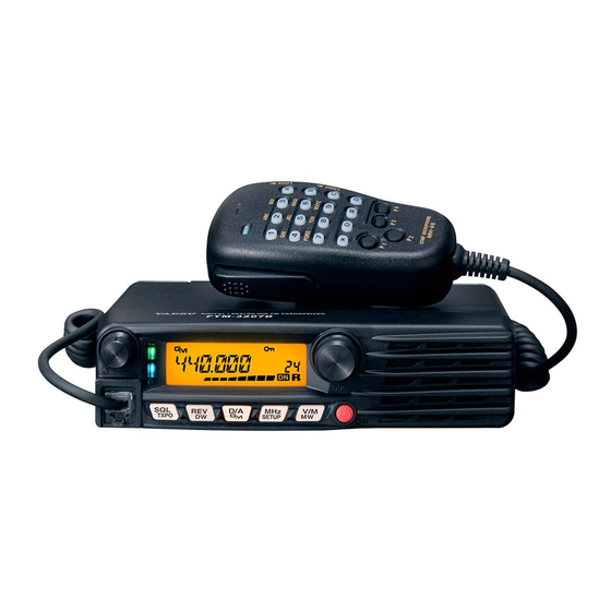
Yaesu FTM-3207DE Operating Manual
Uhf digital/analog transceiver c4fm/fm
Hide thumbs
Also See for FTM-3207DE:
- Manual (2 pages) ,
- Advance manual (35 pages) ,
- Advance manual (35 pages)

Related Manuals for Yaesu FTM-3207DE


Summary of Contents for Yaesu FTM-3207DE
- Page 1 FTM-3207DR/DE Operating Manual UHF DIGITAL/ANALOG TRANSCEIVER C4FM/FM DIAL M H z V / M TXPO SETUP...
-
Page 2: Table Of Contents
Contents Safety Precautions ( Be Sure to Read ) ....3 DCS Operation ............28 FTM-3207DR/DE Quick Reference Guide ....5 DCS Search ............29 Introduction ............... 6 EPCS (Enhanced Paging & Features of this radio ..........6 Code Squelch) Operation ........29 Accessories &... -
Page 3: Safety Precautions ( Be Sure To Read )
Be sure to read these important precautions, and use this product safely. Yaesu is not liable for any failures or problems caused by the use or misuse of this product by the purchaser or any third party. Also, Yaesu is not liable for damages caused through the use of this product by the purchaser or any third party, except in cases where ordered to pay damages under the laws. - Page 4 Never cut off the fuse holder of the DC power Do not pull the cable when plugging and unplug- cord. ging the power cord and connection cables. This may cause short-circuiting and result in ignition Please hold the plug or connector when unplugging. and fire.
-
Page 5: Ftm-3207Dr/De Quick Reference Guide
FTM-3207DR/DE Quick Reference Guide VOL Knob Frequency DIAL Knob Adjusts the audio Selects the operating Frequency. volume level. DIAL M H z V / M TXPO SETUP Power Switch Press and hold for one second. Transmission Switch ... -
Page 6: Introduction
Congratulations on your purchase of the FTM-3207DR/DE! Whether this is your first rig, or if Yaesu equipment is already the backbone of your station, the Yaesu organization is committed to ensuring your enjoyment of this high-performance transceiver. It should provide you with many years of satisfying operation. -
Page 7: Accessories & Options
Accessories & Options Supplied Accessories DTMF Microphone Mobile Mounting Bracket DC power cable w/Fuse MH-48A6JA (Attachment screw set) Operating Manual Warranty Card Spare fuse (25 A) USB cable (20 A, European version) Optional Accessories MH-42C6J Microphone MH-48A6JA DTMF Microphone MLS-100 High-Power External Speaker FP-1030A AC Power Supply (USA/EXP market only) -
Page 8: Installation
Installation Connecting the Microphone Connect the supplied MH-48A6JA microphone to the FTM-3207DR/DE. Plug the microphone connector into the MIC jack on the front panel until it clicks. Note: When disconnecting the microphone, pull the cable while pressing the connector latch. PQRS WXYZ Microphone... -
Page 9: Mobile Installation
Installation Mobile Installation The FTM-3207DR/DE must only be installed in vehicles having a 13.8 Volt negative ground electrical system. Mount the transceiver where the display, controls, and micro- phone are easily accessible, using the supplied mounting bracket. The transceiver may be installed in almost any location, but should not be positioned near a heating vent nor anywhere where it might interfere with driving (either visually or mechanically). -
Page 10: Power Connection
Installation Power connection To minimize voltage drop and avoid blowing the vehicle’s fuses, connect the supplied DC power cable directly to the battery terminals. Do not attempt to defeat or bypass the DC cable fuse - it is there to protect you, your transceiver, and your vehicle’s electrical system. -
Page 11: Base Station Installation
20 Amps continuously at 13.8 Volts DC. The FP-1023 (USA market only) and FP-1030A (USA/EXP market only) AC Power Supplies are available from your Yaesu dealer to satisfy these requirements. Other well-regulated power supplies may be used as well, if they meet the above voltage and current specifications. -
Page 12: Front Panel Controls & Switches
Front Panel Controls & Switches Front Panel DIAL M H z V / M TXPO SETUP VOL knob Turning the knob clockwise increases the volume, whereas turning it counterclock- wise decreases the volume. - Page 13 Press and hold the key in for over one second to activate the Dual Watch feature. Note: For details, refer to the Advanced Manual (download from the Yaesu website). [ D/A ( GM )] key ...
-
Page 14: Microphone Switches
You can reprogram the [ P3 ] , and [ P4 ] buttons for other functions, if desired. Note: For details, refer to the Advanced Manual (download from the Yaesu website). Speak into this port during transmission. -
Page 15: Rear Panel Connectors
DATA Jack Use this jack when updating the firmware. When a new firmware update for the FTM- 3207DR/DE is available, go to the YAESU website to download the programming data and update the FTM-3207DR/DE to its newest state. ... -
Page 16: Basic Operation
This feature al- lows setting the squelch so that only signals exceeding a certain S-meter level will open the squelch. For de- tails, refer to the Advanced Manual (download from the Yaesu website). FTM-3207DR/DE Operating Manual... -
Page 17: Frequency Navigation
Basic Operation Frequency Navigation Using the Dial Rotating the DIAL knob allows tuning in the pre-programmed steps. Clockwise rotation tunes the frequency upwards, whereas coun- DIAL terclockwise rotation tunes the frequency M H z V / M TXPO SETUP downwards. r Press the [ MHz ( SETUP )] key momentarily, then rotate the DIAL knob, to change the fre- quency steps to 1 MHz per step. -
Page 18: Selecting The Communication Mode
Basic Operation Selecting the communication mode The FTM-3207DR/DE transceiver is equipped with the AMS (Automatic Mode Select) function which automatically selects from two modes of transmission corresponding to the signal being received. The transmit mode is selected according to the received signal so that C4FM digital sig- nals, and analog signals are received and transmitted automatically. -
Page 19: Setting The Transmission Mode When Using The Ams Function
Basic Operation Setting the transmission mode when using the AMS function TXMANUAL (“ ” blinks: 1 sec on, 0.5 sec off) Automatically selects one of the two communication modes according to the received signal. Briefly pressing [ PTT ] on the microphone switches between digital mode and analog mode. -
Page 20: Transmission
Note: Keep the microphone about 5 cm away from your mouth. The sensitivity (gain) of the microphone can be adjusted. For details, refer to the Advanced Manual (download from the Yaesu website). 3. Release PTT. The transmit mode/status indicator turns off and the transceiver returns to the receive mode. -
Page 21: Adjusting The Transmit Power
Basic Operation Adjusting the transmit power When communicating with a nearby station, the transmit power level may be lowered to reduce the battery power consumption. 1. Press and hold the [ SQL ( TXPO )] key for over one second. 2. -
Page 22: Advanced Operation
Advanced Operation About the Digital Group ID (DG-ID) feature The DG-ID function can set up two-digit DG-ID numbers from “00” to “99” separately for Transmit and Receive. By setting both transmit and receive to “00” (default), you can communicate with all the other stations in the digital C4FM mode. By matching the transmit DG-ID number to the uplink DG-ID number set in the club DR- 2X/XE System Fusion II digital repeater, you can access the digital repeater DR-2X/XE used in the club. -
Page 23: Recall And Use The Dg-Id Number Registered In The Dg-Id Memory
Advanced Operation • Use the numeric keys on the microphone or the DIAL knob to input the characters of the DG-ID tag. Up to 8 characters can be entered. Press the [P3] key on the microphone or [SQL (TXPO)] key to move the cursor to the left. -
Page 24: Restore The Dg-Id Number To "00" For Both Transmit And Receive Without Using The Dg-Id Memory
Advanced Operation 4. Press the [P1] key on the microphone to switch to the DG-ID number display as shown below. When the DG-ID memory is "00", no DG-ID tag is displayed, only the DG-ID number "00" is displayed. Normal Screen (Frequency) DG-ID Tag display ... -
Page 25: Digital Personal Id (Dp-Id) Feature
Advanced Operation Digital Personal ID (DP-ID) feature Every C4FM digital transmit communication contains the individual ID information (Radio ID) of each transceiver. The DP-ID function uses this individual ID information. When communicating with another transceiver, if the DP-ID of the stations are registered in each other‘s transceivers, they can communicate even if the DG-ID numbers are different. -
Page 26: Deleting The Registered Dp-Id
Advanced Operation 5. Press and hold the [D/A(GM)] key to save the setting. • When registering in the DP-ID list is finished, “Completed” is displayed, then the display returns to the DP-ID list screen. • To continue operating without registering the DP-ID, press the [D/A(GM)] key. -
Page 27: Advanced Operation
Tone Calling (1750 Hz) If your transceiver is FTM-3207DE (European version), press and hold in the program key [ P4 ] of the microphone (MH-48) to generates a 1750 Hz burst tone to access the European repeater. -
Page 28: Ctcss Operation
Note: For details, refer to the Advanced Manual (download from the Yaesu website). DCS Operation This radio is equipped with a DCS (Digital Coded Squelch) function that allows audio to be heard only when signals containing the corresponding DCS code are received. -
Page 29: Dcs Search
DCS code scan to search for and identify the DCS code being used. Note: For details, refer to the Advanced Manual (download from the Yaesu website). The following features are also available: EPCS (Enhanced Paging & Code Squelch) Operation Use the pager code consisting of two CTCSS tones to exchange communications with specified stations. -
Page 30: Memory Operation
A separate transmit frequency may be registered to a memory channel to which a receive frequency has already been registered. Note: For details, refer to the Advanced Manual (download from the Yaesu website). Naming a Memory Channel You may also append an alphanumeric “Tag” (label) to each memory, to aid in recollection of the channel’s use (such as club name, etc.). -
Page 31: Memory Recall
Moving Memory Data to the VFO Data stored on memory channels can easily be moved to the VFO. Note: For details, refer to the Advanced Manual (download from the Yaesu website). Memory Only Mode Once memory channel programming has been completed, you may place the radio in a “Memory Only”... -
Page 32: Masking Memories
Memory Operation Masking Memories There may be situations where you want to “Mask” memories so they are not visible during memory selection or scanning. (except for Memory Channel “1”, the Priority Chan- nel, and the Home Channel). 1. In the Memory Recall mode, press and hold the [ V/M ( MW )] key for one second, then rotate the DIAL knob to select the memory DIAL... -
Page 33: Scanning
Scan Resume Options Select which of the three resume scan modes is to be performed after the scanning stops. Note: For details, refer to the Advanced Manual (download from the Yaesu website). Memory Skip Scanning Memory channels which you do not want to receive can be skipped during scanning. -
Page 34: Gm Function
GM Function What is the GM (Group Monitor) Function? The GM function automatically monitors the channel for any other stations with the GM function in operation on the same frequency, or stations transmitting in DN mode that are within communication range. You can be notified of GM stations operating within com- munications range, and the detected call signs are displayed on the transceiver screen, Caution: The GM function does not work while in the analog (FM) mode. -
Page 35: Reset Procedure/Clone
FTM-3207DR/ This can be particularly useful when configuring a number of transceivers for a public service operation. Note: For details, refer to the Advanced Manual (download from the Yaesu website). FTM-3207DR/DE Operating Manual... -
Page 36: Connecting The Wires-X Feature
Connecting the WIRES-X feature What is WIRES-X? WIRES-X is an Internet communication system which expands the range of amateur radio communication. You may employ Internet communications by connecting from your transceiver to a WIRES-X local node station. * FTM-3207DR/DE does not accommodate the transmission/reception of messages, images, audio messages, or location information. - Page 37 Connecting the WIRES-X feature After successfully connecting to the node, one of the following screens is displayed indicating the node status. r 1.Node ID screen (the Node Lc screen) • This screen is displayed if the node is disconnected from the other node or the room on the Internet.
- Page 38 Connecting the WIRES-X feature • Registering the node/room: Press and hold the [1]-[5] key to register the node/room (C1-C5) on the connected node ID or room ID (Cn). • Cancelling the connected node/room: Select the node/room (C1-C5) then press and hold the [C] key to delete the registered node/room.
-
Page 39: Connect And Communicate With Wires-X In Analog Mode
WIRES-X mode. Note: About WIRES-X open node stations A listing of the WIRES-X open node stations, with their location, operation mode, etc. is posted on the Yaesu WIRES-X website. https://www.yaesu.com/jp/en/wires-x/index.php Connect and communicate with WIRES-X in analog mode In analog mode, specify the connection destination using DTMF signals. -
Page 40: Miscellaneous Settings
[ P4 ] keys at the factory. The user may change these key function assignments, if quick access to another function is desired. Note: For details, refer to the Advanced Manual (download from the Yaesu website). Keyboard Beeper A key/button beeper provides useful audible feedback whenever a key/button is pressed. -
Page 41: Displaying The Supply Voltage
(band edge beeper) when the frequency reaches the band edge while selecting the VFO frequency manually, using the DIAL knob. Note: For details, refer to the Advanced Manual (download from the Yaesu website). FTM-3207DR/DE Operating Manual... -
Page 42: Setup (Menu) Mode
[ MHz ( SETUP )] key for one second to exit the Setup menu and resume normal operation. Note: For details, refer to the Advanced Manual (download from the Yaesu website). Menu Item Function Available Values... - Page 43 Setup (Menu) Mode Menu Item Function Available Values Default Setting of the DTMF Autodialer TX Delay 16: DT DELAY 50/250/450/750/1000 450 MS Time. Loading of the DTMF Autodialer Memo- 17: DT SET ries. Setting of the DTMF Autodialer Sending 18: DT SPEED 50/100 50 MS Speed.
- Page 44 Setup (Menu) Mode Menu Item Function Available Values Default 38: SCAN SKP Selects the Memory Scan mode. OFF/SKIP/SELECT Enables/Disables the split CTCSS/DCS 39: SQL EXP ON/OFF coding. Selects the Tone Encoder and/or Decod- TONE/TSQL/DCS/ 40: SQL TYPE er mode. RV TONE/PAGER/OFF AUTO/5/6.25/10/12.5/15 41: STEP Sets the frequency synthesizer steps.
-
Page 45: Maintenance
Maintenance Care and maintenance Turn the power OFF before wiping away any dust and stains on the transceiver with a dry soft cloth. For stubborn stains, slightly moisten a soft cloth and wring it out before using it to wipe away the stains. Caution: Never use washing detergents and organic solvents (thinner, benzene, etc.). -
Page 46: Specifications
Specifications General Frequency Range: Tx 430 - 450 MHz(USA version) 430 - 440 MHz(European version) 420 - 470 MHz(Asian version) Rx 420 - 470 MHz Channel Step: 5/6.25/10/12.5/15/20/25/50/100 kHz Standard Repeater Shift: ±5 / 7.6 MHz Frequency Stability: ±2.5 ppm [-4 °F to +140 °F (-20 °C to +60 °C)] Modes of Emission: F2D/F3E/F7W Antenna Impedance:... - Page 47 An amateur band radio doesn’t require Certification/Verification for the transmitter under Part 97 z Changes or modifications to this device that are not expressly approved by YAESU MUSEN could void the user’s authorization to operate this device. z This device complies with part 15 of the FCC Rules. Operation is subject to the following two con- ditions: ( 1 ) This device may not cause harmful interference, and ( 2 ) this device must accept any interference including received, interference that may cause undesired operation.
-
Page 48: Eu Declaration Of Conformity
Telephone: (714) 827-7600 EU Declaration of Conformity We, Yaesu Musen Co. Ltd of Tokyo, Japan, hereby declare that this radio equipment FTM-3207DE is in full compliance with EU Radio Equipment Directive 2014/53/EU. The full text of the Declaration of Conformity for this product is available to view at http://www.yaesu.com/jp/red ATTENTION –... - Page 50 Copyright 2018 YAESU MUSEN CO., LTD. All rights reserved. No portion of this manual may be reproduced without the permission of YAESU MUSEN CO., LTD. YAESU MUSEN CO., LTD. Tennozu Parkside Building 2-5-8 Higashi-Shinagawa, Shinagawa-ku, Tokyo 140-0002 Japan YAESU USA 1801I-CO-1 6125 Phyllis Drive, Cypress, CA 90630, U.S.A.