Table of Contents
Advertisement
For more information, visit www.desatech.com
For more information, visit www.desatech.com
CBN20, CBP20
SBN20, SBP20
CBN20T, CBP20T
CBN30T, CBP30T
CBT20NT, CBT20PT
CBT30NT, CBT30PT
CBN20TK, CBP20TK
WARNING: If the information in this manual is not
followed exactly, a fire or explosion may result caus-
ing property damage, personal injury, or loss of life.
— Do not store or use gasoline or other flammable
vapors and liquids in the vicinity of this or any
other appliance.
— WHAT TO DO IF YOU SMELL GAS
• Do not try to light any appliance.
• Do not touch any electrical switch; do not use any
phone in your building.
• Immediately call your gas supplier from a
neighbor's phone. Follow the gas supplier's in-
structions.
• If you cannot reach your gas supplier, call the fire
department.
— Installation and service must be performed by a
qualified installer, service agency, or the gas
supplier.
This appliance may be installed in an aftermarket*, permanently located, manufactured
(mobile) home, where not prohibited by local codes.
This appliance is only for use with the type of gas indicated on the rating plate. This
appliance is not convertible for use with other gases.
*Aftermarket: Completion of sale, not for purpose of resale, from the manufacturer
Save this manual for future reference.
Save this manual for future reference.
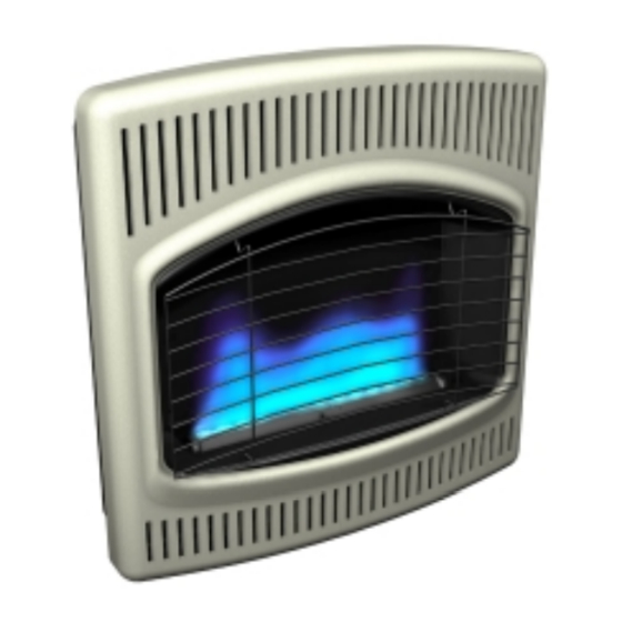
UNVENTED (VENT-FREE)
BLUE FLAME GAS HEATER
SAFETY INFORMATION AND
INSTALLATION MANUAL
WARNING: Improper installation,
adjustment, alteration, service, or
maintenance can cause injury or
property damage. Refer to this
manual for correct installation and
operational procedures. For as-
sistance or additional information
consult a qualified installer, ser-
vice agency, or the gas supplier.
WARNING: This is an unvented
gas-fired heater. It uses air (oxy-
gen) from the room in which it
is installed. Provisions for ad-
equate combustion and venti-
lation air must be provided.
Refer to Air for Combustion and
Ventilation section on page 4 of
this manual.
Advertisement
Table of Contents

Related Manuals for Comfort Glow SBN20


Summary of Contents for Comfort Glow SBN20
- Page 1 UNVENTED (VENT-FREE) BLUE FLAME GAS HEATER SAFETY INFORMATION AND INSTALLATION MANUAL For more information, visit www.desatech.com For more information, visit www.desatech.com CBN20, CBP20 SBN20, SBP20 CBN20T, CBP20T CBN30T, CBP30T CBT20NT, CBT20PT CBT30NT, CBT30PT CBN20TK, CBP20TK WARNING: Improper installation, WARNING: If the information in this manual is not...
-
Page 2: Table Of Contents
TABLE OF CONTENTS SAFETY INFORMATION TABLE OF CONTENTS SAFETY INFORMATION ............2 SERVICE HINTS ............... 16 LOCAL CODES ................3 TECHNICAL SERVICE ............. 16 PRODUCT IDENTIFICATION ............. 3 SERVICE PUBLICATIONS ............16 UNPACKING ................3 TROUBLESHOOTING .............. 17 PRODUCT FEATURES .............. 3 ILLUSTRATED PARTS BREAKDOWN AND PARTS LIST .. -
Page 3: Local Codes
SAFETY INFORMATION LOCAL CODES PRODUCT IDENTIFICATION UNPACKING PRODUCT FEATURES SAFETY INFORMATION PRODUCT IDENTIFICATION 3. If you smell gas Control Knob & Ignitor Button • shut off gas supply (not seen from this view) Heater • do not try to light any appliance Cabinet •... -
Page 4: Air For Combustion And Ventilation
AIR FOR COMBUSTION AND VENTILATION Providing Adequate Ventilation AIR FOR COMBUSTION AND VENTILATION Unusually tight construction is defined as construction WARNING: This heater shall not be installed in a where: confined space or unusually tight construction un- a. walls and ceilings exposed to the outside atmosphere less provisions are provided for adequate combustion have a continuous water vapor retarder with a rating and ventilation air. - Page 5 AIR FOR COMBUSTION AND VENTILATION Determining Fresh-Air Flow For Heater Location AIR FOR COMBUSTION AND VENTILATION Continued DETERMINING FRESH-AIR FLOW FOR Compare the maximum Btu/Hr the space can support with the actual amount of Btu/Hr used. HEATER LOCATION __________________ Btu/Hr (maximum the space can support) Determining if You Have a Confined or __________________ Btu/Hr (actual amount of Btu/Hr used) Unconfined Space...
- Page 6 AIR FOR COMBUSTION AND VENTILATION Ventilation Air AIR FOR COMBUSTION AND VENTILATION Continued VENTILATION AIR 12" Ventilation Air From Inside Building This fresh air would come from an adjoining unconfined space. When ventilating to an adjoining unconfined space, you must Ventilation Grills provide two permanent openings: one within 12"...
-
Page 7: Installation
INSTALLATION Check Gas Type Installation Items Locating Heater INSTALLATION NOTICE: This heater is intended for use as supple- WARNING: Never install the heater mental heat. Use this heater along with your primary • in a bedroom or bathroom heating system. Do not install this heater as your •... - Page 8 INSTALLATION Thermostat Sensing Bulb Installing Heater To Wall INSTALLATION Continued THERMOSTAT SENSING BULB Removing Front Panel Of Heater Remove the four painted screws, two on each side of front panel. The thermostat sensing bulb has been placed inside the heater for 2.
- Page 9 INSTALLATION Installing Heater To Wall (Cont.) INSTALLATION Continued 2. Mark screw locations on wall (see Figure 8). Attaching To Wall Anchor Method Note: Only mark last hole on each end of mounting bracket. For attaching mounting bracket to hollow walls (wall areas between Insert mounting screws through these holes only.
- Page 10 INSTALLATION Installing Heater To Wall (Cont.) Mounting Heater To Floor INSTALLATION Continued Installing Bottom Mounting Screws MOUNTING HEATER TO FLOOR (OPTIONAL) 1. Locate two bottom mounting holes. These holes are near bot- Mounting Base Feet to Heater tom on back panel of heater (see Figure 12). 1.
- Page 11 INSTALLATION Connecting To Gas Supply INSTALLATION Continued CONNECTING TO GAS SUPPLY Typical Inlet Pipe Diameters 20,000 Btu/Hr Models - 3/8" or greater WARNING: This appliance requires a 3/8" NPT 30,000 Btu/Hr Models - 1/2" or greater (National Pipe Thread) inlet connection to the pres- Installation must include equipment shutoff valve, union, and sure regulator.
- Page 12 INSTALLATION Checking Gas Connections INSTALLATION Continued CHECKING GAS CONNECTIONS Pressure Testing Heater Gas Connections 1. Open equipment shutoff valve (see Figure 16). WARNING: Test all gas piping and connections, 2. For natural gas open main gas valve located on or near gas internal and external to unit, for leaks after installing meter.
-
Page 13: Operating Heater
OPERATING HEATER For Your Safety Read Before Lighting Lighting Instructions OPERATING HEATER Note: You may be running this heater for the first time FOR YOUR SAFETY READ after hooking up to gas supply. If so, the control knob may BEFORE LIGHTING need to be pressed in for 30 seconds or more. -
Page 14: Inspecting Heater
OPERATING HEATER To Turn Off Gas To Appliance Thermostat Control Operation Manual Lighting Procedure INSPECTING HEATER Pilot Flame Pattern OPERATING HEATER INSPECTING HEATER Continued Check pilot flame pattern and burner flame pattern often. PILOT FLAME PATTERN TO TURN OFF GAS TO APPLIANCE Figure 21 shows a correct pilot flame pattern. -
Page 15: Cleaning And Maintenance
INSPECTING HEATER Burner Flame Heater CLEANING AND MAINTENANCE ODS/Pilot and Burner Cleaning Burner Pilot Air Inlet Cabinet INSPECTING HEATER ODS/PILOT AND BURNER Continued • Use a vacuum cleaner, pressurized air, or small, soft bristled brush to clean. BURNER FLAME PATTERN BURNER PILOT AIR INLET The primary air inlet holes allow the proper amount of air to mix with WARNING: If yellow tipping occurs, your heater... -
Page 16: Specifications
SPECIFICATIONS SERVICE HINTS TECHNICAL SERVICE SERVICE PUBLICATIONS SPECIFICATIONS CBN20/CBN20T CBN30T CBT20NT CBT30NT SBN20 Btu (Variable) 10,000/20,000 15,000/30,000 10,000/20,000 15,000/30,000 Type Gas Natural Only Natural Only Natural Only Natural Only Ignition Piezo Piezo Electronic Electronic Pressure Regulator Setting 3" W.C. 3" W.C. -
Page 17: Troubleshooting
TROUBLESHOOTING TROUBLESHOOTING Note: For additional help, visit DESA WARNING: Turn off and unplug CAUTION: Never use a wire, Heating Products’ technical service web needle, or similar object to clean heater and let cool before servic- site at www.desatech.com. ODS/pilot. This can damage ODS/ ing. - Page 18 TROUBLESHOOTING TROUBLESHOOTING Continued OBSERVED PROBLEM POSSIBLE CAUSE REMEDY Burner does not light after ODS/pilot is lit 1. Burner orifice is clogged 1. Clean burner (see Cleaning and Mainte- nance, page 15) or replace burner orifice 2. Inlet gas pressure is too low 2.
- Page 19 TROUBLESHOOTING TROUBLESHOOTING Continued WARNING: If you smell gas • Shut off gas supply. • Do not try to light any appliance. • Do not touch any electrical switch; do not use any phone in your building. • Immediately call your gas supplier from a neighbor’s phone. Follow the gas supplier’s instructions.
-
Page 20: Illustrated Parts Breakdown And Parts List
ILLUSTRATED PARTS BREAKDOWN Models CBN20, CBP20, SBN20 and SBP20 ILLUSTRATED PARTS BREAKDOWN MODELS CBN20 CBP20 SBN20 SBP20 For more information, visit www.desatech.com For more information, visit www.desatech.com 107882-01H... - Page 21 PARTS LIST Models CBN20, CBP20, SBN20 and SBP20 PARTS LIST This list contains replaceable parts used in your heater. When ordering parts, follow the instructions listed under Replacement Parts on page 26 of this manual. PART NUMBER KEY CBN20 CBP20 NO.
- Page 22 ILLUSTRATED PARTS BREAKDOWN Models CBN20T, CBP20T, CBN30T, CBP30T, CBN20TK, and CBP20TK ILLUSTRATED PARTS BREAKDOWN MODELS CBN20T, CBP20T CBN30T, CBP30T CBN20TK, CBP20TK For more information, visit www.desatech.com For more information, visit www.desatech.com 107882-01H...
- Page 23 PARTS LIST Models CBN20T, CBP20T, CBN30T, CBP30T, CBN20TK, and CBP20TK PARTS LIST This list contains replaceable parts used in your heater. When ordering parts, follow the instructions listed under Replacement Parts on page 26 of this manual. PART NUMBER FOR KEY CBN20T CBP20TK CBN20TK...
- Page 24 ILLUSTRATED PARTS BREAKDOWN Models CBT20NT, CBT20PT, CBT30NT, and CBT30PT ILLUSTRATED PARTS BREAKDOWN Alkaline MODELS Battery CBT20NT, CBT20PT CBT30NT, CBT30PT Install Battery According To This Illustration (Determine which ignitor your heater uses) Battery Positive Battery Negative For more information, visit www.desatech.com For more information, visit www.desatech.com 107882-01H...
- Page 25 PARTS LIST Models CBT20NT, CBT20PT, CBT30NT, and CBT30PT PARTS LIST This list contains replaceable parts used in your heater. When ordering parts, follow the instructions listed under Replacement Parts on page 26 of this manual. PART NUMBER FOR CBT20NT CBT20PT CBT30NT CBT30PT DESCRIPTION...
-
Page 26: Replacement Parts
WARRANTY INFORMATION KEEP THIS WARRANTY Model Serial No. Date Purchased Always specify model and serial numbers when communicating with the factory. We reserve the right to amend these specifications at any time without notice. The only warranty applicable is our standard written warranty. We make no other warranty, expressed or implied.