Advertisement
Quick Links
ANDERSON GREENWOOD TYPE 91 AND 94 PILOT OPERATED SAFETY RELIEF VALVES
INSTALLATION AND MAINTENANCE INSTRUCTIONS
Before installation these instructions must be fully read and understood
TABLE OF CONTENTS
2. Main valve maintenance ............................... 2
3. Pilot maintenance ......................................... 4
4. Pilot set pressure adjustment ...................... 8
5. Accessory repair .......................................... 10
6. Leak testing assembly ................................ 11
8. Repair kits .................................................... 12
The intent of these instructions is to acquaint
the user with the storage, installation and
operation of this product. Please read these
instructions carefully before installation.
SAFETY PRECAUTIONS
When the pressure relief valve is under pressure
never place any part of your body near the pilot
exhaust nor the outlet of the main valve.
The main valve outlet should be piped or vented to
a safe location.
Always wear proper safety gear to protect head,
eyes, ears, etc. anytime you are near pressurized
valves.
Never attempt to remove the pressure relief valve
from a system that is pressurized.
Never make adjustments to or perform
maintenance on the pressure relief valve while
in service unless the valve is isolated from
the system pressure. If not properly isolated from
the system pressure, the pressure relief valve
may inadvertently open resulting in serious injury.
Emerson.com/FinalControl
Remove the pressure relief valve prior to
performing any pressure testing of the system.
The safety of lives and property often depends
on the proper operation of the pressure relief
valve. The valve must be maintained according to
appropriate instructions and must be periodically
tested and reconditioned to ensure correct function.
WARNING
Removal of the seal wires in an attempt to adjust
and/or repair this product by unauthorized or
unqualified persons voids the product warranty
and may cause damage to equipment and serious
injury or death to persons.
The product is a safety related component intended
for use in critical applications. The improper
application, installation or maintenance of
the product or the use of parts or components not
manufactured by Anderson Greenwood may result
in a failure of the product.
Any installation, maintenance, adjustment, test, etc.
performed on the Product must be done in
accordance with the requirements of all applicable
Anderson Greenwood Procedures and Instructions
as well as applicable National and International
Codes and Standards.
STORAGE AND HANDLING
Pressure relief valve performance may be
adversely affected if the valve is stored for an
extended period without proper protection.
Rough handling and dirt may damage, deform,
or cause misalignment of valve parts and may
alter the pressure setting and adversely affect
valve performance and seat tightness. It is
recommended that the valve be stored in the
original shipping container in a warehouse
or as a minimum on a dry surface with a
protective covering until installation. Inlet and
outlet protectors should remain in place until
the valve is ready to be installed in the system.
© 2021 Emerson. All Rights Reserved.
1 GENERAL VALVE DESCRIPTION AND
START-UP
1.1 Operation
The Anderson Greenwood Pilot Operated Safety-
Relief Valves utilize the principle of backloading
the top, or large area, of a differential area
bellows with line pressure to hold the bellows
closed up to set pressure. At set pressure
the pilot valve relieves, partially evacuating
the dome (volume in the bellows) and the bellows
lifts permitting discharge from the main valve.
When the pilot reseats, line pressure is diverted
to the dome closing the main valve.
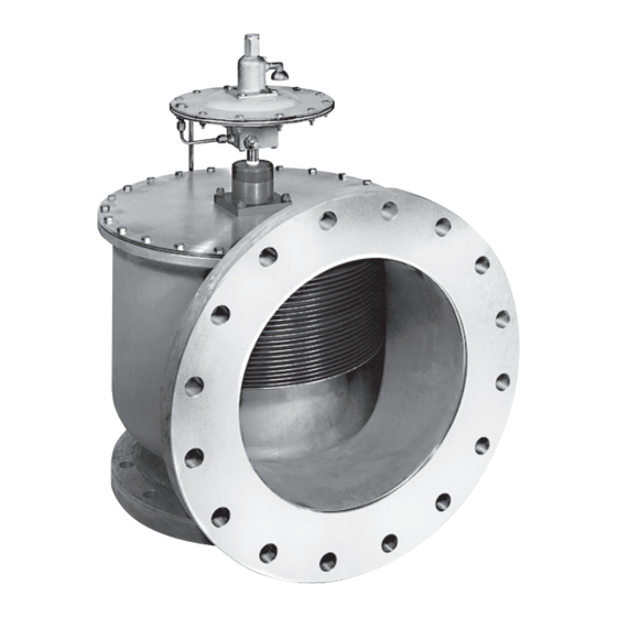
1.2 Installation
The valve should be installed in accordance
with accepted piping practices, in an upright
position as shown in Figure 1.
When remote pressure pick-up is used the pilot
supply tube is connected to a remote location
rather than to the inlet neck of the valve. If a
block valve is used in the remote pilot supply
line, be sure it is opened before pressurizing
the system or opening the isolating block valve
under the main valve, if one is used.
NOTE
Remote pressure pick-up piping must have
the equivalent flow area of ½" (15 mm) tubing for
lengths up to 20 feet (6.1 m). For lengths greater than
20 feet (6.1 m), larger tubing or pipe should be used.
Engineering Doc. #05.9040.080 Rev. K
VCIOM-06025-EN 21/06
Advertisement

Related Manuals for Emerson 91


Summary of Contents for Emerson 91
-
Page 1: Table Of Contents
ANDERSON GREENWOOD TYPE 91 AND 94 PILOT OPERATED SAFETY RELIEF VALVES INSTALLATION AND MAINTENANCE INSTRUCTIONS Before installation these instructions must be fully read and understood 1 GENERAL VALVE DESCRIPTION AND Remove the pressure relief valve prior to START-UP performing any pressure testing of the system. -
Page 2: Main Valve Maintenance
ANDERSON GREENWOOD TYPE 91 AND 94 PILOT OPERATED SAFETY RELIEF VALVES INSTALLATION AND MAINTENANCE INSTRUCTIONS 1.3 Start-up in order to isolate them when maintenance There must be pressure at the valve inlet to is required. When putting the safety valve in establish a differential in force across the service be sure the block valve is fully opened. - Page 3 ANDERSON GREENWOOD TYPE 91 AND 94 PILOT OPERATED SAFETY RELIEF VALVES INSTALLATION AND MAINTENANCE INSTRUCTIONS 2.3 Assembly cap may be tilted, causing the bellows and Assemble in reverse order of disassembly. seat plate to tip and the seat to leak. Some If the nozzle was removed from the body,...
-
Page 4: Pilot Maintenance
ANDERSON GREENWOOD TYPE 91 AND 94 PILOT OPERATED SAFETY RELIEF VALVES INSTALLATION AND MAINTENANCE INSTRUCTIONS 3 PILOT MAINTENANCE 3.2.4 Type 91 pilots used on valves for marine service have a PTFE sense diaphragm. Refer to Figure 3, 4 and 5 Standard Type 91 pilots use a stainless 3.1 Disassembly... - Page 5 ANDERSON GREENWOOD TYPE 91 AND 94 PILOT OPERATED SAFETY RELIEF VALVES INSTALLATION AND MAINTENANCE INSTRUCTIONS View A - A (Low pressure pilot) Type 94 (Elastomer seat) Exhaust Type 91 (PTFE seat) FIGURE 3 Item Description Item Description NOTES Body Spindle...
- Page 6 ANDERSON GREENWOOD TYPE 91 AND 94 TYPE OPERATED SAFETY RELIEF VALVES INSTALLATION AND MAINTENANCE INSTRUCTIONS Item Description FIGURE 4 Type 91 Body Nozzle Boost spacer Sense spacer Sense plate Boost plate Bonnet assembly Upper diaphragm case Lower diaphragm case Spacer ring...
- Page 7 ANDERSON GREENWOOD TYPE 91 AND 94 PILOT OPERATED SAFETY RELIEF VALVES INSTALLATION AND MAINTENANCE INSTRUCTIONS Item Description FIGURE 5 Type 94 Body Nozzle Hex spacer Boost spacer Sense plate Boost plate Bonnet assembly Upper diaphragm case Lower diaphragm case Spacer ring...
-
Page 8: Pilot Set Pressure Adjustment
ANDERSON GREENWOOD TYPE 91 AND 94 PILOT OPERATED SAFETY RELIEF VALVES INSTALLATION AND MAINTENANCE INSTRUCTIONS 4.0 PILOT SET PRESSURE ADJUSTMENT NOTE If the blowdown adjusting screw has been moved 4.1 Pilot adjustment or turned to either extreme, positioning it midway Two adjustments are provided;... - Page 9 ANDERSON GREENWOOD TYPE 91 AND 94 PILOT OPERATED SAFETY RELIEF VALVES INSTALLATION AND MAINTENANCE INSTRUCTIONS 4.6 Definitions Set pressure is defined as that pressure where the dome pressure is 15% of the supply pressure. Crack pressure is defined as the supply pressure were gas flow begins at the pilot exhaust.
-
Page 10: Accessory Repair
ANDERSON GREENWOOD TYPE 91 AND 94 PILOT OPERATED SAFETY RELIEF VALVES INSTALLATION AND MAINTENANCE INSTRUCTIONS 5 ACCESSORY REPAIR FIGURE 7 5.1 Check valve The check valves used on the Dual pilot, Backflow preventer, and Field test consist of an upper body, a lower body, and a diaphragm. -
Page 11: Leak Testing Assembly
ANDERSON GREENWOOD TYPE 91 AND 94 PILOT OPERATED SAFETY RELIEF VALVES INSTALLATION AND MAINTENANCE INSTRUCTIONS 6 LEAK TESTING ASSEMBLY 7 PILOT SET PRESSURE FIELD TEST PROCEDURE 6.1 General 7.1 General The complete valve assembly should be leak The pilot set pressure can be checked in tested for internal and external leaks using a the field by applying an external test pressure... -
Page 12: Repair Kits
ANGMC-6025-EN © 2014, 2021 Emerson Electric Co. All rights reserved 06/21. Anderson Greenwood is a mark owned by one of the companies in the Emerson Automation Solutions business unit of Emerson Electric Co. The Emerson logo is a trademark and service mark of Emerson Electric Co. All other marks are the property of their prospective owners.