Table of Contents
Advertisement
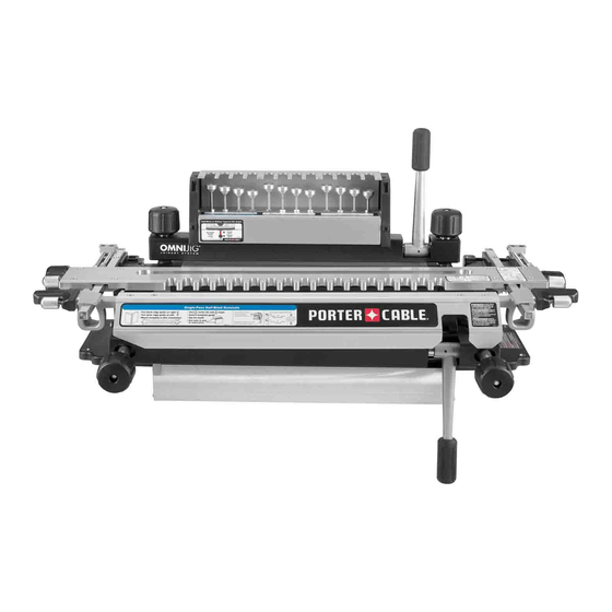
OMNIJIG
®
JOINERY SYSTEM
Instruction manual
www.deltaportercable.com
A20465
A24502 - 11-16-07 Rev. A
Product may vary slightly
Product may vary slightly from photo.
from picture.
Le produit peut être légèrement différer de la photo.
El artículo puede variar levemente con relación a la foto.
55160
(22428)
77240
(25192)
Copyright © 2007 PORTER-CABLE
RTD10000496AA
Advertisement
Table of Contents

Related Manuals for Porter-Cable OMNIJIG 55160


Summary of Contents for Porter-Cable OMNIJIG 55160
- Page 1 Product may vary slightly from photo. from picture. Le produit peut être légèrement différer de la photo. El artículo puede variar levemente con relación a la foto. www.deltaportercable.com 55160 (22428) 77240 (25192) A20465 A24502 - 11-16-07 Rev. A Copyright © 2007 PORTER-CABLE RTD10000496AA...
-
Page 3: Table Of Contents
Models 55160 AND 77240 Applications Safety General safety rules Router safety OMNIJIG ® JOINERY SYSTEM safety Introduction Rabbeted Through Dovetails Joinery overview Half-Blind Dovetails Standard OMNIJIG ® parts OMNIJIG ® accessories Familiarization Wood preparation Project layout Variable-Spaced Board lengths Sliding Tapered Tips for making drawers and boxes Dovetails Half-Blind Dovetails... -
Page 4: General Safety Rules
If you have any questions relative to its application DO NOT use the tool until you have written PORTER-CABLE and we have advised you. You can write to Technical Service Manager; PORTER-CABLE; 4825 Highway 45 North; Jackson, TN 38305. - Page 5 Introduction This chapter gives you some background knowledge of dovetail and other joints and how to prepare the wood for a successful project. We'll also explain the basic parts of the ® OMNIJIG JOINERY SYSTEM and tell you about accessories ®...
-
Page 6: Joinery Overview
JOINERY OVERVIEW The dovetail joint is a traditional joint which dates all the way back to the ancient Egyptians. It is both strong and visually appealing. This joint has flared protrusions (tails) (A) Fig. 1 that are cut into one board ("tailboard") and protrusions with slanted sides (pins) (B) that are cut in the other board ("pinboard"). - Page 7 ® STANDARD OMINJIG PARTS 77240 The OMNIJIG ® comes standard with various bits, template guides, stops and a template. ® The 24" OMNIJIG comes standard with a variable finger template that is used to cut through dovetails and half-blind dovetails (variable and single-pass).
- Page 8 ® OMNIJIG ACCESSORIES 77245 55165 An accessory kit available for the OMNIJIG ® help you cut box joints (16" or 24"). In addition, different templates are available: a 16" variable finger template; a 24" single-pass half-blind/ sliding tapered dovetail template; and 24" and 16" miniature variable finger templates.
- Page 9 3/8" 1-17/32" 1/2" NOTE: Other router bits and other accessories (dust collection adapter, storage box for tools, etc.) are 31/64" 1-17/32" 1/2" available to expand the capabilities of your OMNIJIG ® . Contact your nearest PORTER-CABLE dealer for more information.
-
Page 10: Familiarization
FAMILIARIZATION B. Finger set. These are either variable fingers G. Template mounting rod lock knobs (as shown) or fixed (not shown). H. Template lock knobs C. Router bit depth gauge Stabilizer bar You need to be familiar with the basic parts D. -
Page 11: Wood Preparation
WOOD PREPARATION Properly preparing the materials for your project is the key to good-looking and tight-fitting joints. You must cut your wood at perfect right angles (Fig. 13). Cuts that are off even one degree will not align correctly (Fig. 14). Also, your workpieces must be flat and not cupped. -
Page 12: Board Lengths
BOARD LENGTHS To determine what length your workpieces should be in a typical dovetail drawer project, first visualize your final project and determine the following: What kind of joints will you use on the front of the drawer and on the back of the drawer? What are the outside dimensions of the resulting drawer? What is the tail height (the distance "Y"... -
Page 13: Tips For Making Drawers And Boxes
TIPS FOR MAKING DRAWERS AND BOXES Tails (A) Fig. 25 are cut into the sides of the drawers, while pins (B) are cut into the fronts and backs of drawers. You can use either solid wood or plywood for the drawer bottoms. - Page 15 Basic Operations...
-
Page 16: Variable-Spaced Half-Blind Dovetails
SETTING UP THE OMNIJIG ® In addition to the manual, there are a number of in- ® structional labels located on the OMNIJIG , plus set- up guide cards (standard with some models) that are provided to help guide you through the various ap- plications that can be achieved. -
Page 17: Bench Mounting
BENCH MOUNTING ® The OMNIJIG base is designed so it can be either clamped to the edge of a sturdy workbench (as shown in Fig. C1) or bolted to the table through the holes (A) ® Fig. C1 provided in the base. The OMNIJIG should be secured using one of these mounting methods at all times. -
Page 18: Typical Omnijig Adjustments
TYPICAL OMNIJIG ADJUSTMENTS PLACING AND SIZING STOPS Setup for all joints includes the selection of either single or double stops (D and E) Fig. C5 included with your unit. Two stops are necessary - one for the left and one for the ®... -
Page 19: Accessory Templates
ACCESSORY TEMPLATES Single-pass half-blind/sliding Templates included with the Omnijig are pre-set, but before plac- tapered dovetail fixed finger ing an accessory template onto the bars for the first time, you will template need to make a one-time adjustment: Eight screws (four shown) Loosen (do not remove) square-head screws on both sides of the templates. -
Page 20: Variable Fingers
For horizontally mounted workpieces (W) always include a scrap piece (V) Fig. C13 of the same thickness on the opposite side to ensure flatness of the template and to provide stability. NOTE: Before mounting the wood, it may help to remove the stabilizer bar (J) Fig. -
Page 21: Selecting Bits And Template Guides
While the finger pairs (DD) Fig. C15 can be placed anywhere for your variable-spaced joints, they usually move together, as shown at (DD). When they are separated (EE) – do not cut between the flat edge area (FF). Only cut in the angled area (GG). SELECTING BITS AND TEMPLATE GUIDES Your choice of template guide (JJ) Fig. -
Page 22: Through Dovetails
DOVETAIL SETUP GUIDE The Dovetail Setup Guide is included with the 24" OMNI- ® and any variable finger accessory (miniature or stan- dard size). The card describes what stops, bits and tem- plate guides are needed to make standard and miniature through dovetails, variable-spaced half-blind dovetails and single-pass half-blind dovetails. -
Page 23: Variable-Spaced Half-Blind Dovetails
ROUTER BIT DEPTH POD ® 24" OMNIJIG The router bit depth pod comes standard with the 16" and ® 24" OMNIJIG ® For the 24" OMNIJIG (Model 77240), the gauges come pre-set to help you set the bit depth for : Variable-spaced half-blind dovetails Single-pass half-blind dovetails ®... -
Page 24: Making Cuts
MAKING CUTS SAFE CUTTING When making cuts: TIP FOR REDUCING TEAR-OUT DURING CUTS ACCESSORIES DUST COLLECTION ® ®... -
Page 25: Storage Case Positioning
When adding the stabilizer bar back onto the OMNIJIG when the dust shroud is attached, tilt the bar (XX) as shown in Fig. C27 and be sure it rests as shown in Fig. C25. STORAGE CASE POSITIONING An accessory storage box (Cat. No. 77249) is available for ®... - Page 27 Through Dovetails...
- Page 28 ITEMS NEEDED ® With the OMNIJIG , through dovetail joints are made by first cutting the tailboard (A) Fig. D1 using a dovetail bit. The pinboard (B) is cut next using a straight bit. You will need: * variable finger template (miniature or standard) * straight bit and dovetail bit * template guide and stops.
- Page 29 After the bulk of the material has been removed, the D6 bit is used with the G1 template guide to complete the cuts on the tails. The pins are then cut using the S2 straight bit and the G5 template guide, as shown on the dovetail setup guide.
- Page 30 Pull horizontal scrap (H) Fig. D6 forward against the back of the vertical tailboard (I), as shown in Fig. D6. Be sure both boards are lined up flush against the left offset guide (J). Position the fingers using the supplied square screwdriver.
- Page 31 13. Slowly lower bit (Q) Fig. D9 onto stop. Depth is set when bit barely touches the stop. Before making any cuts, be sure you read your router owner’s manual for safe operating instructions. 14. Set router onto stabilizer bar with bit between bar and workpiece.
- Page 32 Mount the pinboard (U) Fig. D12 with the “outside surface" facing away from the jig. Be sure it is flush against the left offset guide (J). Mount the template (M) and be sure the end of the pinboard (U) is flush against the bottom of the template.
- Page 33 FITTING THE JOINT Through Pins Adjustments may need to be made depending on the Tightness Dovetails Adjustment resulting fit of the through dovetail joint. (rear stop) Scrap, same Select Looser thickness as Joint straight bit TIGHTNESS tail board and template Tighter guide Joint...
- Page 35 Variable-Spaced Half-Blind Dovetails...
- Page 36 ITEMS NEEDED On the OMNIJIG ® , variable-spaced half-blind joints can be cut using the variable finger template (regular or miniature). The joints are made by cutting the pinboard (drawer front) (A) Fig. E1 first and then the tailboard (drawer side) (B) Fig. E2. Noting your desired tail height, check your "Dovetail Setup Guide"...
- Page 37 CUTTING PINBOARD Insert proper stops (G) Fig. E4 according to the Dovetail Setup Guide. Remove stabilizer bar (H) and template (I). Black edge guide (J) should be on left and silver edge guide (K) should be on the right. Mount the pinboard (L) (drawer front) in the horizontal position with the "outside surface"...
- Page 38 Drop template (I) Fig. E6 down and tighten template lock knobs (one is shown at R). Replace stabilizer bar (H) and lock in place. 10. Using your selected tail height as reference, install proper dovetail bit and template guide according to the "Dovetail Setup Guide."...
- Page 39 12. Re-install stabilizer bar. 13. Set router onto stabilizer bar with bit between bar and the workpiece and make the cut. NOTE: If you have separated a finger set, be sure to cut only between the angled walls, not between the straight ones.
- Page 40 FITTING THE JOINT Adjustments may need to be made depending on the Half-Blind Bit Depth resulting fit of the joint. If all of the problems below apply, fix them in the order listed below. 1. TIGHTNESS OF FIT To adjust for tightness of joint fit, see the diagram on Looser Bit Depth the half-blind bit depth gauge (Fig.
- Page 41 3. TAILBOARD THICKNESS The OMNIJIG ® is set to create the optimal tail thickness when using 1/2" thick wood. Fig. E19 shows a representation of 1/2" wood with this optimal tail thickness. NOTE: For the fix below, be sure the template is placed on the jig with the label "B TAILS"...
- Page 43 Single-Pass Half-Blind Dovetails...
- Page 44 ITEMS NEEDED ® On the OMNIJIG , single-pass half-blind joints (which are most often used when making drawers) can be cut using the variable finger template and the single-pass half-blind/sliding tapered dovetail template. The joints are made by cutting the pinboard (drawer front) (A) Fig. F1 and F2 and the tailboard (drawer side) (B) at the same time.
- Page 45 SETTING UP AND MAKING THE CUT ® When cutting single-pass half-blind joints, the OMNIJIG system provides on-board instruction labels to help guide you through the process. Use this list to find the proper label for your setup: 24" variable finger template: Instructions on stabilizer bar 16"...
- Page 46 SETUP AND CUTTING FOR BOTH TEMPLATES Remove stabilizer bar (F) Fig. F7 and template (M). Set black edge guide (H) to right and silver edge guide (I) to the left. Insert proper stops (J). Put pinboard (drawer front) (K) in the horizontal position with “outside surface"...
- Page 47 Loosen silver left edge guide (I) Fig. F9 with square driver and move it to the far left position. Slide tailboard (drawer side) (U) Fig. F10 up into the vertical position with the “outside surface" facing the jig and flush with the template above. Center and clamp the tailboard as far to the left as possible, as shown in Fig.
- Page 48 Before making any cuts, be sure you read your router owner’s manual for safe operating instructions. 14. Set router onto stabilizer bar with bit between bar and the workpiece and make the cut. Make a slow climb cut from right to left along vertical tailboard. Then clean out all gaps in both boards moving slowly from left to right.
- Page 49 Rabbeted Half-Blind Dovetails...
- Page 50 RABBETED HALF-BLIND JOINTS Rabbeted half-blind dovetails are often used to create drawer fronts (H) Fig. G1 that have a rabbeted (or lipped) edge. NOTE: Many of the steps used on the OMNIJIG ® when cutting other kinds of half-blind joints are also used to cut the rabbeted half-blind joint.
- Page 51 SETTING UP AND CUTTING THE JOINT (VARIABLE FINGER TEMPLATES) NOTE: Before proceeding, consult the variable-spaced half- blind instructions (or the labels on the unit) for proper set-up. CUTTING THE PINBOARD Clamp the rabbeted pin board (drawer front) (H) Fig. G4 in the horizontal position with the “outside surface" against the jig’s base.
- Page 52 NOTE: Be sure to space the fingers (J) around the tall edges (K) of the workpiece, as shown in Fig. G6. Maintain 1/8" gap at (L). Rabbeted Before making any cuts, be sure you Tail board height read your router owner’s manual for safe operating height instructions.
- Page 53 SETTING UP AND CUTTING THE JOINT (SINGLE-PASS HALF-BLIND/SLIDING TAPERED DOVETAIL TEMPLATE) NOTE: Before proceeding, consult the single-pass half- blind instructions (or the labels on the unit) for proper set-up and other guidance. CUTTING TAILBOARD Mount proper size scrap in horizontal position. Position the tailboard (B) Fig.
- Page 55 Sliding Tapered Dovetails...
- Page 56 ITEMS NEEDED Sliding tapered dovetails are often used to create shelves. This joint is created with a slightly tapered dado (A) Fig. H1 and a tenon (B) that is similarly tapered. The taper keeps the joint from tightening until the last few inches, making assembly easier.
- Page 57 For the shelves (B1, B2 or B3) Fig. H3, the rear edge is mounted vertically to the left of BOTTOM the jig in order to cut the tenon. After making the cuts for the project as laid out in Fig. H3, the cuts will look like boards A1 and A2 in Fig.
- Page 58 SETTING UP AND MAKING THE CUT OPERATIONAL NOTE: When cutting the sliding tapered dovetail joint, light and consistent pressure on the router is key to joint repeatability. Heavy or varied pressure may cause inconsistent joints. Also, before mounting the workpieces, be sure the jig base is free from wood chips or dust build-up.
- Page 59 As described in the "PROJECT LAYOUT" section, be sure the tenon board (shelf) (B) Fig. H10 is oriented with the "rear edge" of the shelf to the left before mounting. Place the tenon board (shelf) vertically against the front of the jig base and mark the left side of the end grain as shown in Fig H10 with an "X".
- Page 60 CUTTING THE DADO BOARD You will use the same stops, bit, template guide and depth of cut for the dado that was used for the tenon. The dado board (vertical side panel, as shown at A1 or A2, Fig H3) will be mounted on the jig horizontally with the out- side surface facing down and the rear edge aligned to the right of the jig base.
- Page 61 ASSEMBLING THE BOARDS Insert tenon board at “X" mark (Fig. H19) into dado’s “X" mark (Fig. H20) and slide in place. A blow with a rubber mallet may be needed for proper fitting. FITTING THE JOINT In the event that adjustments need to be made to achieve the desired joint fit, further instructions are given below: TIGHTNESS: For joints that are deemed too tight, a shallower bit depth is needed to produce a looser joint.
- Page 63 Box Joints...
- Page 64 ITEMS NEEDED Box joints are popular for specific projects such as jewelry boxes, blanket chests, workbenches or storage bins. Box joints of variable finger widths can be made using an accessory box joint kit with the variable finger template (Fig. I1) or the miniature finger template (Fig.
- Page 65 NOTES ON CUTTING THE BOX JOINT Before we get into the steps for cutting box joints, here are a few key points about using the box joint accessory kits with the appropriate templates: For other applications such as through and half-blind dovetails, the position of the template or the router bit depth is used to control the tightness of the joint.
- Page 66 VARIABLE FINGER TEMPLATE (55261 or 77241) CUTTING THE FIRST BOARD (B1) Mount horizontal scrap boards (F) Fig. I6 and template (G). Be sure the “B PINS” label (H) is to the left as you face the jig. Vertically mount the first board to be cut (B1) Fig.
- Page 67 Your router bit depth should match the thickness of the second board you are cutting, or B2 (Fig. I9). This is the board that will be joined with the first board, B1. To set router bit depth, mark a line (M) Fig. I9 on B1 using the thickness of B2, as shown.
- Page 68 CUTTING THE SECOND BOARD (B2) Flip template over so the “B TAILS” label (P) Fig. I14 is on the left as you face the jig. Remove the first board B1 and mount the second board B2, noting that the "outside surface" of second board B2 should now be facing away from the jig.(See Fig.
- Page 69 ADJUSTING FOR TIGHTNESS OF FIT VARIABLE FINGER TEMPLATE MINI FINGER TEMPLATE VARIABLE FINGER TEMPLATE If the resulting joint is too loose, you will need to re-cut B2 with a different template guide to TEMPLATE GUIDE TEMPLATE GUIDE tighten the joint. To do so: Make sure template is mounted with “B TAILS”...
-
Page 70: Appendix
GENERIC SINGLE STOP SETTINGS SIZING YOUR OWN STOPS Single Distance "X" (Fig. 1) Single Stop The stops included with the OMNIJIG ® stop label decimal fractional JOINERY SYSTEM and other accessories are pre-set to be used with the parts they 2.357 2-23/64"... - Page 71 ROUTER BIT DEPTH POD SETTINGS SINGLE-PASS HALF-BLIND/SLIDING TAPERED DOVETAIL TEMPLATES (16” - 55168; 24" - 77248) ® The OMNIJIG comes standard with a router bit depth pod (detail shown below in Fig. 4.) The four left and four middle gauges of the router bit depth pod that is standard with the 16"...
- Page 72 90 DAY MONEY BACK GUARANTEE: If you are not completely satisfied with the perfor- All quality tools will eventually require servicing and/or replacement of parts. For infor- mance of your PORTER-CABLE Power Tool, Laser, or Nailer for any reason, you can return mation about PORTER-CABLE, its factory service centers or authorized warranty ser- it within 90 days from the date of purchase with a receipt for a full refund –...
- Page 73 The gray & black color scheme is a trademark for PORTER-CABLE Power Tools and Accessories. The following are also trademarks for one or more PORTER-CABLE and Delta products: L ’agencement de couleurs grise et noire est une marque de commerce des outils électriques et accessoires PORTER-CABLE. Les marques suivantes sont également des marques de commerce se rapportant à...
- Page 76 4825 Highway 45 North Jackson, TN 38305 1.888.848.5175 deltaportercable.com/jigs ©Copyright 2007 PORTER-CABLE. All rights reserved.