Table of Contents
Advertisement
Advertisement
Table of Contents

Related Manuals for Porter-Cable 513


Summary of Contents for Porter-Cable 513
- Page 1 Instruction manual Lock Mortiser and Lock Face Template MODEL 513 Mortiser MODEL 517 Lock Face Template IMPORTANT! Please make certain that the person who is to use this equipment carefully reads and understands these instructions before starting operations. ®...
-
Page 2: Safety Guidelines - Definitions
SAFETY GUIDELINES - DEFINITIONS It is important for you to read and understand this manual. The information it contains relates to protecting YOUR SAFETY and PREVENTING PROBLEMS. The symbols below are used to help you recognize this information. indicates an imminently hazardous situation which, if not avoided, will result in death or serious injury. -
Page 3: General Safety Rules
GENERAL SAFETY RULES Read all instructions. Failure to follow all instructions listed below may result in electric shock, fire and/or serious injury. The term "power tool" in all of the warnings listed below refers to your mains-operated (corded) power tool or battery-operated (cordless) power tool. - Page 4 GENERAL SAFETY RULES continued Use safety equipment. Always wear eye protection. Safety equipment such as dust mask, non-skid safety shoes, hard hat, or hearing protection used for appropriate conditions will reduce personal injuries. Avoid accidental starting. Ensure the switch is in the off-position before plugging in.
-
Page 5: Additional Specific Safety Rules
ADDITIONAL SPECIFIC SAFETY RULES Hold tool by insulated gripping surfaces when performing an operation where the cutting tools may contact hidden wiring or its own cord. Contact with a “live” wire will make exposed metal parts of the tool “live” and shock the operator. -
Page 6: Extension Cord Selection
MOTOR Many Porter-Cable tools will operate on either D.C., or single phase 25 to 60 cycle A.C. current and voltage within plus or minus 5 percent of that shown on the specification plate on the tool. Several models, however, are designed for A.C. -
Page 7: Carton Contents
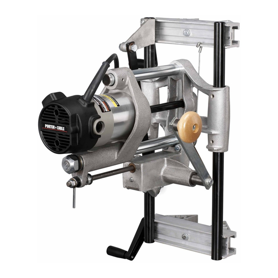
* Mortiser frame FUNCTIONAL DESCRIPTION FOREWORD The Model 513 Lock Mortiser permits builders and contractors to quickly cut true, accurate mortises for door-box locks. The Model 517 Lock-Face Template allows quick and economical routing for lock faces on doors after the mortise has been completed. -
Page 8: Operation
Use PORTER-CABLE #43704PC 1" (25.4 mm) diameter bit. 2) Overall width of lock box – 3/4" (19.1 mm) Use PORTER-CABLE #43703PC 3 /4" (19.1 mm) diameter bit. Various sizes of bits are available as accessories. DISCONNECT THE TOOL FROM THE POWER SOURCE and exercise extreme care when handling the cutter to avoid bodily injury or damage to the cutting edge. - Page 9 SETTING MORTISER FOR LENGTH OF CUT Disconnect tool from power source! Set the mortiser for the length of cut (Fig. 6). Loosen the crank pin nut (T) and turn the adjusting knob (U) until the correct graduation mark on the slide aligns with the line on the crank-pin indicating washer.
- Page 10 Move the feed lever (A) to the horizontal position (Fig. 8). Pull the motor carriage (B) to the end of the guide rod (C). Place the mortiser against the edge of the 2" x 6" so that the clamps are firmly seated.
- Page 11 Disconnect tool from power source! Turn the mortiser crank handle until the bit is in the top-most position. Place the mortiser on the door so that the top edge of the bit touches the line drawn on edge of the door. Mortise the door as instructed in "MAKING A TRIAL CUT".
- Page 12 LOCATING THE TEMPLATE ON THE DOOR Draw a line across the door edge at the center of the mortise cut for the lock. Draw a line (F) Fig. 13 on the template side guides (C), midway between bars (B) and (E). Position the template on door so that the line (F) on the template matches the line drawn on the door edge at the center of the mortise cut.
-
Page 13: Maintenance
FACTORY SERVICE CENTER. At approximately 100 hours of use, take or send your tool to your nearest authorized Porter-Cable Service Station to be thoroughly cleaned and inspected. Have worn parts replaced and lubricated with fresh lubricant. Have new brushes installed, and test the tool for performance.