
Related Manuals for Carrier XCT 7 40VCC727FQEE


Summary of Contents for Carrier XCT 7 40VCC727FQEE
- Page 1 Operation & Installation Manual MODEL NAME 40VCC727FQEE No. 0150545929 Edition: 2020-11...
- Page 2 Centralized controller function 1. This controller can control VRF system, single split and supermatch (or multi) , etc., Connecting to VRF can control up to 800 indoor units, and connecting single split and Supermatch (or Multi) can control up to 256 indoor units ①...
- Page 3 2.2 Zone management. The equipment can be divided into three levels: building - floor - zone. Support zone creation, edit, delete and other functions. 2.3 Achieve the setting of ON/OFF, mode, wind speed, temperature setting, centralized control mode, and swing angle of all indoor units in individual control/zone control /all control/custom groups control mode.
- Page 4 2.16 Third-party device management function, supporting the access of third-party devices controlled by I/O through Carrier gateway, such as lighting, fans, curtains, etc. Implement the proposed building automation control functions 2.17 Network setting function, supporting local network setting, WiFi access and LAN access.
- Page 5 2.19 Device data backup and recovery function: The configuration of the current system can be backed up by the external USB flash disk, or the configuration files that have been exported can be restored to the device. 2.20 Advanced setting function. Advanced setting refers to other ancillary setting functions, including switching temperature unit, region and language,...
-
Page 6: Power Light
Description of centralized ON/OFF key Power on and start automatically. Press the key for 3 seconds to turn off, Press one time to turn on Touch/display Display and Operation area Screen saver key Press to turn off screen light anf press again to turn on Power light Power light will be on after powering on Reset key... - Page 7 USB1/USB2 You can insert U disk to import and export data Audio Connect the loudspeaker device Connected to ground Terminal Function terminals for gateway communication Gigabit network port, double access Power Connect the power adapter...
- Page 8 COM2 Gateway address 1-32 can be set to connect VRF models COM3 Gateway address 1-128, Connect to gateway "40VCAR17FQEE" COM6 Reserved fire alarm COM5 ModBUS-RTU centralized control data interface COM4 Connect to a third-party gateway, gateway address: 1-128 COM1 Gateway address 1-32 can be set to connect VRF models...
- Page 9 Centralize the connection between the controller and the gateway Outdoor bus Outdoor bus COM2 MAX-32 COM1 MAX-32 Outdoor bus Outdoor bus...
- Page 10 Gateway address setting For the units connected to centralized controller, it is required to use indoor units’ dip switch or address setting remote controller to set the indoor units address, which is convenient for inspection and maintenance. Control VRF models For every system of VRF, address starts from No.1 to last indoor unit of the system.
- Page 11 Connect the unit air conditioner 40VCAR17FQEE gateway is used when the centralized controller is connected to unit air conditioner, and the maximum number of connections is 128 COM3 MAX-128 Upper computer centralized control...
-
Page 12: Single Mode
2. 40VCAR17FQEE address setting Control single split or multi type One indoor unit needs to be configured with one 40VCAR17FQEE converter. The address of 40VCAR17FQEE can be set as below SW01 define Single mode Dual units switching mode Switching time1: 8 hours Switching time2: 10 hours Switching time3: 12 hours Switching time1: 24 hours... -
Page 13: System Architecture
System architecture... -
Page 14: Controller Initialization
1 Controller initialization The controller is powered on and starts automatically. After the hardware is started, it enters the software loading interface. Please wait for the software loading to complete. 2、First login interface To use the controller for the first time, a controller activation process is required. The controller activation process is mainly used to set the initialization state of the controller 2.1 Language selection ①... -
Page 15: Network Settings
2.2 Network Settings ① Click the select network and select "LAN1/LAN2/WLAN", where "LAN1/;AN2 "refers to the wired network, which corresponds to" LAN1 "and" LAN2 "respectively printed on the screen at the wiring position. When "WLAN" is selected, it means networking with wifi. The "Select WLAN" function button can be used to search the current network and connect. -
Page 16: Time Setting
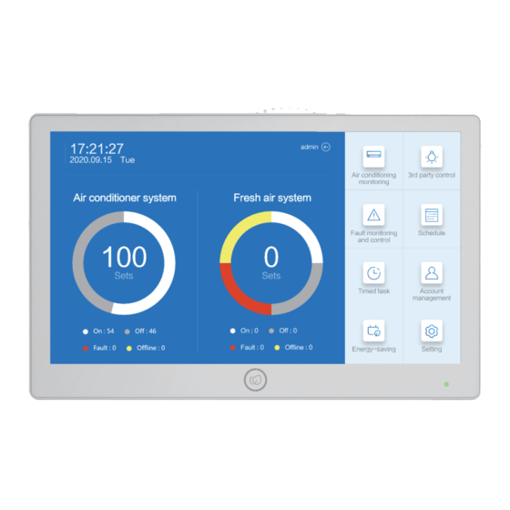
2.3 Time setting The time setting interface can set the time and date, and the initial setting needs to set "date" and "time", using the 24-hour system. Slide to set the current time, select the time and click "OK" to enter the next step. Click “Back” to discard the current Settings and return to the previous action. - Page 17 2.5 Enter standby interface The current interface can be switched to enter the user name and password. After entering the user name and password, click "Login" to use the centralized control function. 3、Equipment control function 3.1 Home page The main interface is used to monitor the working status of the current system and enter the control function through the right shortcut key.
- Page 18 Main monitoring interface 3.2.1 Device Monitor - Icon mode Monitoring interface ⑫ ⑬ ⑪ ⑩ ⑨ ⑭ ⑧ ⑥ ④ ③ ② ① ⑤ ⑦ ① Time, displays the current time ② Network connection , Displays wired/wireless status of current access type ③...
- Page 19 temperature/wind speed/mode/centralized control mode/timing task status" and other information air conditioner icon model Name environm fan speed ent temp. Centralized/timed set temp. mode HRV icon name Indoor/outdoor model temperature Centralized mode/timed fan speed state / Mesh state FAU icon name model ndoor/outdoor temperature...
- Page 20 Cancel/control uncheck selected ⑪Display mode switch, “ ” Represents icon mode, “ ” Represents list mode, “ ” Represents floor navigation mode ⑫Display machine switch, T his can be set from the drop-down menu "all/air conditioning/fresh air/HRV". So that only the selected device can be displayed in the current area air conditioner unit Total heat exchanger unit...
- Page 21 Fresh air unit ⑬Contents, Click on the switch "Buildings/Floors/Groups" ⑭ Device/partition display 3.2.2 Device monitor - list mode The monitor interface has a list mode in addition to the icon display interface , You can view setup information and troubleshooting. All devices" cannot be selected in list mode. Only one of the devices IDU/fresh air /HRV"...
- Page 22 The following picture shows the monitoring interface of the HRV list mode ① ② ③ ④ ⑥ ⑤ ⑦ ① name:Device name, display the current device name ② mode:Mode of the device, display the operating mode of the device ③ speed:Fan speed ④...
- Page 23 The following picture shows the monitoring interface of the fresh air list mode ① ② ③ ④ ⑥ ⑤ ⑦ ① name:Device name, display the current device name ② mode:Mode of the device, display the operating mode of the device ③...
- Page 24 3.2.3 Equipment monitoring - floor navigation mode Use of floor navigation system, Easy to quickly find an indoor units .The control interface is shown in the picture below Floor navigation map ② ③ ① ① Status display. The interface can display the four basic states of "power on/power off/failure/offline". The current wind speed and temperature mode of the IDU cannot be displayed ②...
- Page 25 3.2.4 Partition monitoring - Icon mode You can switch to partition monitoring mode to view the details of the current partition ① ② ① Click the button of "Fully on/Fully off" to open all equipment in the building. Click "Fully Off" to close all equipment in the current floor or building ②...
- Page 26 ③ When a machine has set the timer mode, click on the blue circle to enter the Settings mode, You can view the detailed Settings, as shown in the picture below ④ The timing task of the current partition can be quickly switched through the switch button, click one to switch the state.
- Page 27 HRV monitoring display is similar to IDU monitoring display, but the details are different, as shown in the figure below. ① ② ④ ③ ⑤ ⑥ ① Full on/full off , Click full on or full off to turn all HRV on or off ②...
- Page 28 3.3 Control function of air conditioning 3.3.1 Air conditioning control interface Click to enter the control interface, Parameters can be set on the control interface. After setting, Click send to complete setting. ⑩ ⑧ ⑦ ⑨ ⑥ ⑤ ④ ③ ②...
- Page 29 ⑧ Swing air/electric heating function, click “ ” to set the swing function, when the icon is highlighted, it display the up-down swing icon.Click “ ” , to highlight it .Activate electric heating function ⑨ Click the "Execute" button to set the current function to the selected IDU. ⑩...
- Page 30 3.3.2 HRV control HRV control interface, as shown in the figure below ⑥ ① ③ ④ ⑤ ② ① Mode and air quality parameters display, showing the current operating mode, the mode is divided into "automatic/full heat/bypass/fresh air/exhaust air/internal circulation", when installing optional air quality sensing equipment, this point is the air quality parameter.
- Page 31 3.3.3 Fresh air unit interface The new fan control interface is used to set the control state of the new fan ⑤ ① ③ ② ④ ① Mode and air quality parameters display, showing the current operating mode, ② ON/OFF button .to switch ON and OFF the controller. ③...
- Page 32 3.3.4 Floor navigation and monitoring interface Floor navigation interface ① ② ① The current zooming function does not development temporarily, and this function will be canceled. ② The icon shows the current device state. Click the popup control interface. The position of the control interface is the same as that of the icon and list monitoring interface.
- Page 33 3.5 Third-party device monitoring Third-party equipment monitoring is used to monitor third-party equipment compatible with the centralized controller, such as lighting, new fans, etc ③ ④ ① ② ⑤ ⑥ ① searching bar. Used to search 3 party device zone, you can enter key word to search the device which is convenient to manage.
- Page 34 3.6 Fault Device Configuration Equipment fault monitoring is divided into two parts: real-time fault alarm and history alarm. Real-time alarm is mainly used to check the current equipment fault, while fault history is used to check the faults that have occurred in the equipment, so as to facilitate follow-up maintenance and troubleshooting. 3.6.1 Current Fault ②...
- Page 35 ③ Checking button, you can check the current failure alarm For detailed information, you can view "device name/fault code/fault description/IDU address/start time/partition information/possible reasons", etc., if the displayed information is not complete, you can click to view the details ⑤ When the display information is too long, you can click to view the detailed information in the popover...
- Page 36 3.6.2 History Fault History fault query shows current and history fault, according to the date of query, the time of deletion according to the time of fault occurrence, not the end time of fault search .Compared with real-time faults, historical fault query added the information of the alarm start and stop time of faults. Delete the "probable cause"...
- Page 37 ⑤ Detail menu, display information divided into "device name/fault code/fault description/master address/start time/end time/partition information".When the information display is not complete, click on the popover to see the details.
- Page 38 3.6.3 Current Pre-Alarm The early warning query is mainly used to check the threshold alarm set in the system. The early warning parameter setting can be set by your setting through the service manual. When the parameter value exceeds the setting range, an alarm can be issued. Note: The setting of the threshold alarm can be adjusted by itself, and the reported warning and fault are independent of each other.
- Page 39 ③ Click query to update the current alert ④ For detailed information, you can view "parameters/current value/bus address/alarm start time/partition information/alarm level", etc. If the display is not complete, you can click to view the details ⑤ When the display information is too long, you can click to view the detailed information in the popover 3.6.4 History Pre-Alarm When the parameters return to normal, the warning will reset automatically and look up the warning from the History Pre-Alarm.
- Page 40 ⑤ Detail menu, display information divided into "device name/fault code/fault description/master address/start time/end time/partition information". When the information display is not complete, click(…) to see the details. on the popover 3.7 Air conditioning commissioning Air conditioning commissioning function is used to search and add air conditioning equipment in the system. It can automatically go online "indoor units/fresh air duct/HRV/third-party equipment".
- Page 41 Click "COM1/COM2" to update the bus, and all the indoor units under the current line will be automatically grouped and named according to different gateways. ② ③ ① ④ ① Click the filter button to select "All/edited/unedited" to improve commissioning efficiency ②...
- Page 42 ③ Automatic online button, Click “ ” , to enter the process of automatic on-line. Nothing else can be done while the device is executing. After the on-line completion, it will automatically generate all the indoor units that are currently on-line, but will not automatically delete the devices that are not currently on-line. Device deletion can only be done manually.
- Page 43 Click "+" to manually add the indoor units, as shown in the popover below. When manually adding, all parameter items are allowed to be modified. Click "OK" to add the device manually ③ Automatic online button,Click “ ” , to enter the automatic on-line process. Nothing else can be done while the device is executing.
- Page 44 3.7.3 fresh air duct commissioning interface Fresh air duct commissioning, click "COM1/COM2" to update the bus, and automatically launch all Fresh air duct under the current line, which are automatically grouped and named according to different gateways ② ③ ① ④...
-
Page 45: Partition Setting
③ Automatic online button,Click “ ” , to enter the automatic on-line process. Nothing else can be done while the device is executing. After the on-line completion, it will automatically generate all the indoor units that are currently on-line, but will not automatically delete the devices that are not currently on-line.Device deletion can only be done manually. - Page 46 3.8.2 Floor and zone setting Convenient interface for floor and grouping, used for editing floor and partition equipment ④ ③ ② ⑤ ① ① Click the floor name to view the floor details and display the zones under the current floor in the right interface ②...
-
Page 47: Floor Layout
⑤zone, displaying the current zone name and sliding to display devices within the zone. Or click to edit the device in the zone, and then the "Add/delete" button pops up. After clicking the "Add" button, when entering the zone edit, only the currently ungrouped devices are displayed for the convenience of viewing the addition After clicking the "Delete"... - Page 48 3.9.1 Add a map The current function only supports adding a map to the floor. After selecting the floor, click "Change the Map" to add a map ② ③ ① ④ ① On the navigation bar, click toggle or view the floor ②...
- Page 49 3.9.2 Adjust map equipment After the map is added, click/drag to adjust the device on the map ① ① Click the model with a non-zero number of devices on the device end, select the corresponding indoor unit from the drop-down menu, and drag it to the area where it is located, then release it and add it ②...
- Page 50 3.10 Third-party device Settings Click to edit the group of third-party devices, and click the following function icon for function management Third party device setting, using single-layer grouping setting, is independent from the device partition to facilitate partition management. ③ ①...
- Page 51 ④ Grouping, displaying the current group name and sliding to display devices within the group.Or click to edit the device in the group, and then the "Add/delete" button pops up. After clicking the "Add" button, when entering the grouping edit, only the currently ungrouped devices are displayed for the convenience of viewing the addition After clicking the "Delete"...
-
Page 52: Alarm Setting
3.11 Alarm setting The alarm setting function is used to set the trigger setting of parameter warning and alarm prompt setting 3.11.1 Alarm trigger setting Alarm setting function supports threshold alarm and alarm fault prompt setting of each parameter item ②... - Page 53 3.11.2 Alarm prompt setting The alarm prompt setting is mainly used to set functions such as which way to use when the system detects a fault or alarms, whether prompt or not.. ② ③ ① ④ ⑤ ① Alarm function setting options, click "Alarm Trigger Setting"/" Alarm Prompt setting" ②...
-
Page 54: Unit Setting
3.12 Unit setting The unit setting function is used to manage the external machine system and check the state parameters of the external machine master and slave The unit setting function is mainly used to manage the external machine. It can check the external machine state quickly, lock the external machine mode and set the system load rate limit. - Page 55 ④ operation of the upper limit of the load rate, such as setting the upper limit of 70%, then the system can automatically adjust the system operating load 0-70%. ⑤ The execution button, after changing the parameter item of "system mode"/" system load ", click to execute release, or click not to release.
-
Page 56: Weekly Schedule
3.13 Weekly Schedule The weekly timing function is mainly used to set the automatic switch of the system, adjust the mode and other functions. . The icon is shown as below. 3.13.1 Weekly scheduled task monitoring The weekly timer task is used to set the schedule for automatic execution.The weekly timing task is the administrator privilege function. - Page 57 ⑤ Timed action, view timed action, click set timed Action Click “ ” to create a new timed task. The following interface pops up and select the mode of timed task.Set the timer task name, select the timer switch, and select the execution mode of the timer task. Cycle: Cycle timing is daily timing.
- Page 58 3.13.1 Cyclic timing task setup The cyclic timing task is used in a fixed setting scenario where the device is on and off ② ③ ④ ⑤ ⑥ ① ⑦ ⑧ ① Timed task view, click to check the set task ②...
- Page 59 ⑧ Click the enabled/disabled button of the current timed action to switch the enabled/disabled state of the current timed action. Enabled means that the current timed action takes effect and the control instruction is issued when the trigger condition of the timed action is satisfied.Deactivation means that no timing condition is issued regardless of whether the trigger condition is met.
- Page 60 ⑥ To enable/disable the timer action button, click toggle the enable/disable status of all timer actions.Enabling means that the current timed action takes effect, and when the trigger condition of the timed action is satisfied, the control instruction is issued.Deactivation means that no timing condition is issued regardless of whether the trigger condition is met.
- Page 61 ④ Sort button, click to toggle sort, sort by name or sort by time Add and delete button, click toggle to add and delete Click "-" to start deletion, click "selected/unselected" to switch the state, after selecting, click to complete deletion of selected items, and click "Cancel"...
- Page 62 3.13.4 Edit timer action A timed action is used to set control instructions to be given to the designated device at a specific time. After selecting the timer task, you can query the timer action by switching tabs, as shown in the figure below ①...
- Page 63 ⑥ The timing device, click to view or switch the range of control instructions issued by the timing device ⑦ Timing details, to check the timing action. And click “ ” , to edit the timed action in the popover Click 'Sent' to save ⑧...
- Page 64 3.13.6 HRV timer function The HRV timing function pop-up window is as follows. You can set "Device type/valid or invalid/name setting/timing setting/timing device/Timing details". ① ② ③ ④ ⑤ ⑥ ⑧ ⑦ ① Device type, you can switch to "air conditioning/Full heat/fresh air" ②...
- Page 65 ⑦ Timing details, check the timing action. And click “ ” , to edit the timing action. ⑧ ⑨ Cancel button, click to cancel the current new/edit timer action ⑩ Save button, click to save the current Settings 3.13.7 New fresh air unit timing function New fresh air timing function pop-up is as follows.
- Page 66 ⑤ Timing device. Click to view or switch the range of control instructions issued by the timing device. ⑥ Timing details, check the timing action. And click “ ” , to edit the timing action. ⑦ Cancel button, click to cancel the current new/edit timer action ⑧...
- Page 67 3.14.1 Set the special day The special day setting is similar to the weekly timing. After the setting is completed and applied, it can be automatically executed no matter whether the account setting schedule is logged in or not.If the setting is invalid, the timed task of this article will be not available.
- Page 68 ⑦ Enable/disable timer action button, click to switch the enabled/disabled state of all timer actions. Enabling means that the current timed action takes effect, and when the trigger condition of the timed action is satisfied, the control instruction is issued. Deactivation means that no timing condition is issued regardless of whether the trigger condition is met.
- Page 69 ④ Click "Apply", click the corresponding date, select the drop-down menu to apply, click "NONE" to cancel the timing task of the current date, click the name of the corresponding menu to select the Special day application 3.15 Timing Program The timing program operation is used to set the account-specific timing function for a specific user.
- Page 70 ② ③ ④ ⑤ ⑥ ① ⑦ ⑧ ① Timing program view, click to switch to view the timing program ② Time program name, click to edit ③ Timed action screening, can choose "all/internal machine/full heat exchanger/new fan", convenient for management ④...
- Page 71 ⑧ ON/OFF button. Enabled means that the current timed action takes effect and the control instruction is issued when the trigger condition of the timed action is satisfied.Deactivation means that no timing condition is issued regardless of whether the trigger condition is met 3.16 Interlock set Interlock setting is used to set the automatic switching function of the full heat exchanger and the new fan equipment...
- Page 72 ⑤ Device tiles, click the operation Settings switch, double click to see the current linkage details 3.16.2 Linkage function setting Click edit linkage Settings ① ② ③ ④ ⑤ ⑥ ⑦ ① Linkage switch, click to switch linkage to set the switching state ②...
- Page 73 3.17 Fire alarm setting Fire alarm setting is used to set fire alarm linkage The fire alarm access point is shown in the figure below Fire access point 1: Connect i1-G Fire access point 2: Connect i2-G Click the following icon to enter the fire alarm function After clicking, make Settings in the Settings screen popover Fire alarm 01: Can be set to normally on/normally off/disabled Fire alarm 02: Can be set to normally on/normally off/disabled...
-
Page 74: User Account
3.18 User Account Account management is used to manage accounts. Set the account name, login password, validity and role Click the icon below to enter The account management interface is as follows. You can set and manage accounts. This function has no permission to set the function. - Page 75 ⑤ The account time, can choose limit/permanent, select "permanent", the current account is valid forever, set the account to "limit", set the account to effective/invalid time ⑥ Account role, set the account role through the drop-down menu ⑦ Mailbox and mobile phone number Settings, enter the current account binding mailbox phone number ⑧...
- Page 76 3.19 Role Permission Role Permission is used to set role permissions and cooperate with account management Role setting functions include data permissions, control permissions, function control and other functions ② ③ ④ ① ⑤ ⑥ ① Role list, view the role list and name, can set a number of different roles ②...
-
Page 77: Region & Language
Delete the role Click "-" to enter the role deletion interface, click "Select" in the role bar, and click "Complete" to delete the selected item. Click Cancel to abort the current operation 3.20 Region & Language The display language can be switched, and the device host and the WEB side set the language respectively, so that the host and the WEB side can browse and control in different languages respectively Slide and click the language, the interface get into the selected language immediately. - Page 78 3.21 Network Settings Network setting function is used to set the device access network information, select the network port, set fixed IP address and other functions. Click the Network Settings icon, and set the Network Information in the Network Setting interface ①...
- Page 79 ② IP address mode setting, you can choose to get the IP address automatically/use the following IP address.When you select "Automatic IP Address acquisition", the host automatically obtains the IP address based on the device.When selecting use the following IP Address, you need to manually set the IP Address/Subnet Mask/gateway ③...
-
Page 80: Brightness Settings
3.23 Brightness Settings The display setting is used to adjust the brightness of the display. The adjustment range is 0-100% The slide Settings take effect immediately.Click "×" to exit 3.24 Volume Settings The sound setting is used to adjust the volume with a range of 0-100% The slide Settings take effect immediately.Click "×"... -
Page 81: Dst(Daylight Saving Time
3.25 DST(Daylight saving time) Daylight saving time is used for special regional daylight saving time. Setting daylight saving time does not affect the display of local time. It is mainly used for adjusting the trigger time of schedule setting.When the daylight saving time is set to 60 minutes, the timed action trigger time is -60 minutes ①... - Page 82 3.26 Switching temperature unit Click the popover to switch the temperature unit.Popover switch "℃/℉" The current state represents the use of Celsius as a temperature unit The current status indicates the use of Fahrenheit as a temperature measure...
-
Page 83: Energy Saving Settings
3.27 Energy saving Settings The energy-saving setting function is used to adjust the upper and lower limits of the temperature setting. After the setting, the temperature range can be set above/under the cooling/heating mode ② ③ ① ① Energy-saving setting icon, can display the current limit and indoor units quantity. Click on the icon to edit Click to switch whether the current limit is effective, set it as effective, limit the set temperature of internal machine operation, set it as invalid, and set the range of internal machine temperature as 16-30℃... - Page 84 ② Add and delete button, click "-" to enter the delete timing setting interface You can select the icon that is set as "invalid". After selecting it, click "Complete" to delete the selected energy saving setting.Click Cancel to abandon the current Settings ③...
-
Page 85: Export Data
3.29 The program update The program update are used to update software version When program updating, the upgrade file in the root directory of U disk run automaticly. Before upgrading, you need to enter the administrator password. Administrator account "admin", enter other account password invalid 3.30 Export data The data export function exports all the configuration in the current host. -
Page 87: Data Recovery
3.31 Data recovery The data recovery function corresponds to the data export function, and the exported data can be restored to the centralized controller Make sure that the USB card is plugged into the central controller, and that the USB card root directory holds a backup of the exported data Enter the password for the "admin"... -
Page 88: Factory Data Reset
3.32 factory data reset Rest factory setting will clear all setting on the central controller Enter the password for the "admin" permission Click OK to start clearing the data Click Cancel to quit the function. -
Page 89: Webserver Function
4 webserver function Webserver setting function. When the central controller is configured, users can connect the central controller remotely and manage the device remotely through PC browser Recommended display resolution: 1920*1080, too high or too low resolution may lead to functional display dislocation Compatible browser: Chrome 83 or above 4.1 Remote login address Settings... - Page 90 The Google browser “chrome” is recommended Enter the url" http://192.168.1.100:8000/“ Open the login screen as follows Enter the username and password to log in.The operation is the same as that of the machine.
- Page 92 The manufacture reserves the right to change any product without notice.