Table of Contents
Advertisement
Quick Links
Advertisement
Chapters
Table of Contents

Related Manuals for MSI MS-98E1


Summary of Contents for MSI MS-98E1
- Page 1 MS-98E1 (v1.x) Industrial Computer Board...
-
Page 2: Revision History
If a problem arises with your system and no solution can be obtained from the user’s manual, please contact your place of purchase or local distributor. Alternatively, please visit the MSI website for technical guide, BIOS updates, driver updates and other information, or contact our technical staff via http://www. -
Page 3: Safety Instructions
MS-98E1 Safety Instructions ■ Always read the safety instructions carefully. ■ Keep this User’s Manual for future reference. ■ Keep this equipment away from humidity. ■ Lay this equipment on a reliable flat surface before setting it up. ■ The openings on the enclosure are for air convection hence protects the equipment from overheating. -
Page 4: Chemical Substances Information
Chemical Substances Information In compliance with chemical substances regulations, such as the EU REACH Regulation (Regulation EC No. 1907/2006 of the European Parliament and the Council), MSI provides the information of chemical substances in products at: http://www.msi.com/html/popup/csr/evmtprtt_pcm.html Battery Information European Union: Batteries, battery packs, and accumulators should not be disposed of as unsorted household waste. -
Page 5: Ce Conformity
MS-98E1 CE Conformity Hereby, Micro-Star International CO., LTD declares that this device is in compliance with the essential safety requirements and other relevant provisions set out in the European Directive. FCC-B Radio Frequency Interference Statement This equipment has been tested and found to comply with the limits for a Class B digital device, pursuant to Part 15 of the FCC Rules. -
Page 6: Table Of Contents
Preface CONTENTS Copyright Notice .................... ii Trademarks ....................ii Revision History .................... ii Technical Support ..................ii Safety Instructions ..................iii Chemical Substances Information ............... iv Battery Information ..................iv CE Conformity ....................v FCC-B Radio Frequency Interference Statement ......... v WEEE Statement .................. -
Page 7: Overview
Overview Thank you for choosing the MS-98E1, an excellent industrial computer board. Based on the innovative Intel C236/ H110 chipset for optimal system ® efficiency, the MS-98E1 accommodates the Intel Skylake-S processor ® and supports up to 2 DDR4 2133MHz SO-DIMM slots to provide the maximum of 32GB memory capacity. -
Page 8: Motherboard Specifications
Overview Motherboard Specifications Processor ■ Intel Core™ i7/ i5/ i3 or Xeon , Celeron series processor ® ® Chipset ■ SKU1: Intel C236 ® ■ SKU2: Intel H110 ® Memory ■ 2 x SO-DIMM slots ■ Dual channel DDR4, up to 2133MHz ■... - Page 9 MS-98E1 Internal I/O ■ 1 x 4-pin power connector ■ 1 x 24-pin power connector ■ 1 x System fan connector ■ 1 x CPU fan connector ■ 1 x USB2.0 connector (2 ports) ■ 1 x USB2.0 port ■ 1 x RS-232 COM port header (4 ports) ■...
- Page 10 Overview Environment ■ Operating Temperature: -10 ~ 60 ■ Storage Temperature: -20 ~ 80 ■ Humidity: 5 ~ 95% RH, non-condensing Form Factor ■ Mini-ITX: 170 mm x 170 mm Certification ■ CE, FCC, BSMI, VCCI, C-Tick SKU Comparison SKUs SKU1 SKU2 Features...
-
Page 11: Motherboard Layout
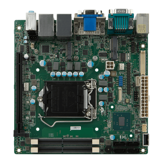
MS-98E1 Motherboard Layout Chassis LVDS Inverter GPIO Intrusion Header Connector Header Jumper AT/ATX LVDS Power COM Port Jumper Jumper Jumper Connector Rear Panel COM Port LVDS Power USB Port Jumper Connector Connector TPM Header SATA Ports System Fan Connector Mini-PCIe Slot... -
Page 13: Hardware Setup
Hardware Setup This chapter provides you with the information about hardware setup procedures. While doing the installation, be careful in holding the com- ponents and follow the installation procedures. For some components, if you install in the wrong orientation, the components will not work prop- erly. - Page 14 Hardware Setup Components Reference Guide CPU (Central Processing Unit) ............2-3 Memory ....................2-6 Power Supply ..................2-7 System Power Connector: PWRCONN1 ...........2-7 CPU Power Connector: JPWR2 ..............2-7 Rear Panel I/O ...................2-8 Connector ..................2-11 Fan Power Connector: CPUFAN1, SYSFAN1 ......... 2-11 Serial ATA Connector: SATA1, SATA2, SATA3, SATA4 (4 x SATA 6Gb/s for SKU1, 3 x SATA 6Gb/s for SKU2) ............
-
Page 15: Cpu (Central Processing Unit)
MS-98E1 CPU (Central Processing Unit) When installing the CPU, make sure that you install the cooler to prevent over- heating. If you do not have the CPU cooler, consult your dealer before turning on the computer. Important Overheating Overheating will seriously damage the CPU and system. Always make sure the cooling fan can work properly to protect the CPU from overheating. - Page 16 Hardware Setup CPU Installation When you are installing the CPU, make sure the CPU has a cooler attached on the top to prevent overheating. Meanwhile, do not forget to apply some thermal paste on CPU before installing the heat sink/cooler fan for better heat dispersion. 1.
- Page 17 MS-98E1 5. Secure the load lever with the hook 6. Make sure the four hooks are in proper under the retention tab. position before you install the cooler. Align the holes on the motherboard with the cooler. Push down the cooler until its four clips get wedged into the holes of the motherboard.
-
Page 18: Memory
Hardware Setup Memory Dual-Channel Mode In Dual-Channel mode, make sure that you install memory modules of the same type and density in different channel DIMM slots. Recommended Memory Population Number of DIMMs installed DIMM1 (ch A) DIMM2 (ch B) Important •... -
Page 19: Power Supply
MS-98E1 Power Supply System Power Connector: PWRCONN1 This connector allows you to connect a power supply. To connect to the power supply, make sure the plug of the power supply is inserted in the proper orienta- tion and the pins are aligned. Then push down the power supply firmly into the connector. -
Page 20: Rear Panel I/O
Hardware Setup Rear Panel I/O Mouse/ RJ45 GbE RJ45 GbE Keyboard Serial Port LAN Port LAN Port Combo Port VGA Port Line-In Line-Out Mic-In USB2.0 HDMI Port DVI-D Port USB3.0 USB3.0 Port Port Port Mouse / Keyboard Combo Port The standard PS/2 mouse/keyboard DIN connector is for a PS/2 mouse/key- ®... - Page 21 MS-98E1 RS-422 SIGNAL DESCRIPTION TXD- Transmit Data, Negative TXD+ Transmit Data, Positive RXD+ Receive Data, Positive RXD- Receive Data, Negative Ground No Connection No Connection No Connection No Connection RS-485 SIGNAL DESCRIPTION Data, Negative Data, Positive No Connection No Connection...
- Page 22 Hardware Setup RJ45 GbE LAN Port The standard single RJ45 LAN jack is provided for connection to the Local Area Network (LAN). You can connect a network cable to it. LED Status Description No link Active Yellow Linked Active LED Speed Blinking Data activity...
-
Page 23: Connector
MS-98E1 Connector Fan Power Connector: CPUFAN1, SYSFAN1 The fan power connectors support system cooling fan with +12V. When con- necting the wire to the connectors, always note that the red wire is the positive and should be connected to the +12V; the black wire is Ground and should be connected to GND. -
Page 24: Chassis Intrusion Header: J1
Hardware Setup Chassis Intrusion Header: J1 This connector connects to the chassis intrusion switch cable. If the computer case is opened, the chassis intrusion mechanism will be activated. The system will record this intrusion and a warning message will flash on screen. To clear the warning, you must enter the BIOS utility and clear the record. -
Page 25: Audio Amplifier Connector: Jspk1
MS-98E1 Audio Amplifier Connector: JSPK1 The connector is used to connect audio amplifiers to enhance audio performance. S/PDIF-Out Connector: JSPDI1 This header is used to connect S/PDIF (Sony & Philips Digital Interconnect For- mat) interface for digital audio transmission. Front Panel Header: JFP1 This front panel connector is provided for electrical connection to the front panel switches &... -
Page 26: Lvds Inverter Connector: Jinvdd1
Hardware Setup LVDS Inverter Connector: JINVDD1 The connector is provided for LCD backlight options. LVDS Connector: JLVDS1 The LVDS (Low Voltage Differential Signal) connector provides a digital interface typically used with flat panels. After connecting an LVDS interface flat panel to the JLVDS1, be sure to check the panel datasheet and set the LVDS jumper to proper power voltage. -
Page 27: Rs-232 Com Port Header: Jcom3
MS-98E1 RS-232 COM Port Header: JCOM3 This connector is a 16550A high speed communications port that sends/receives 16 bytes FIFOs. You can attach serial devices to it through the optional serial port bracket. SIGNAL DESCRIPTION Data Carrier Detect Receive Data... -
Page 28: Jumper
Hardware Setup Jumper Important Avoid adjusting jumpers when the system is on; it will damage the motherboard. Clear CMOS Jumper: J_CMOS1 There is a CMOS RAM onboard that has a power supply from an external battery to keep the data of system configuration. With the CMOS RAM, the system can automatically boot OS every time it is turned on. -
Page 29: Com Port Power Jumper: Jcomp1 (For Jcom1), Jcomp2 (For Jcom3)
MS-98E1 COM Port Power Jumper: JCOMP1 (for JCOM1), JCOMP2 (for JCOM3) These jumpers specify the operation voltage of the onboard serial ports. JCOMP1 (for JCOM1) RI Support JCOMP2 (for JCOM3) +12V LVDS Power Jumper: JVDD1 Use this jumper to specify the operation voltage of the LVDS display. -
Page 30: Slot
Hardware Setup Slot PCIe (Peripheral Component Interconnect Express) Slot The PCI Express slot supports PCIe interface expansion cards. PCIe x16 slot Mini-PCIe (Peripheral Component Interconnect Express) Slot The Mini-PCIe slot is provided for WiFi modules, Bluetooth modules, TV tuner cards and other Mini-PCIe cards. Important When adding or removing expansion cards, make sure that you unplug the power supply first. -
Page 31: Bios Setup
BIOS Setup This chapter provides information on the BIOS Setup program and allows users to configure the system for optimal use. Users may need to run the Setup program when: ■ An error message appears on the screen at system startup and re- quests users to run SETUP. -
Page 32: Entering Setup
BIOS Setup Entering Setup Power on the computer and the system will start POST (Power On Self Test) process. When the message below appears on the screen, press <DEL> or <F2> key to enter Setup. Press <DEL> or <F2> to enter SETUP If the message disappears before you respond and you still wish to enter Setup, restart the system by turning it OFF and On or pressing the RESET button. - Page 33 MS-98E1 Control Keys ← → Select Screen ↑ ↓ Select Item Enter Select Change Option General Help Previous Values Optimized Defaults Save & Reset Exit Getting Help After entering the Setup menu, the first menu you will see is the Main Menu.
-
Page 34: The Menu Bar
BIOS Setup The Menu Bar ▶ Main Use this menu for basic system configurations, such as time, date, etc. ▶ Advanced Use this menu to set up the items of special enhanced features. ▶ Boot Use this menu to specify the priority of boot devices. ▶... -
Page 35: Main
MS-98E1 Main ▶ System Date This setting allows you to set the system date. The date format is <Day>, <Month> <Date> <Year>. ▶ System Time This setting allows you to set the system time. The time format is <Hour> <Min- ute>... -
Page 36: Advanced
BIOS Setup Advanced ▶ Full Screen Logo Display This BIOS feature determines if the BIOS should hide the normal POST mes- sages with the motherboard or system manufacturer’s full-screen logo. When it is enabled, the BIOS will display the full-screen logo during the boot-up sequence, hiding normal POST messages. - Page 37 MS-98E1 ▶ CPU Configuration ▶ Intel Virtualization Technology Virtualization enhanced by Intel Virtualization Technology will allow a platform to run multiple operating systems and applications in independent partitions. With virtualization, one computer system can function as multiple “Virtual” systems. ▶ Active Processor Cores This setting specifies the number of active processor cores.
- Page 38 BIOS Setup ▶ C States This setting controls the C-States (CPU Power states). ▶ Super IO Configuration ▶ Serial Port 1/ 2/ 3/ 4/ 5 This setting enables/disables the specified serial port. ▶ Change Settings This setting is used to change the address & IRQ settings of the specified serial port.
- Page 39 MS-98E1 ▶ H/W Monitor These items display the current status of all monitored hardware devices/ components such as voltages, temperatures and all fans’ speeds. ▶ Smart Fan Configuration ▶ CPUFAN1, SYSFAN1 These settings enable/disable the Smart Fan function. Smart Fan is an ex-...
- Page 40 BIOS Setup ▶ PCIE Device Configuration ▶ Legacy USB Support Set to [Enabled] if you need to use any USB 1.1/2.0 device in the operating system that does not support or have any USB 1.1/2.0 driver installed, such as DOS and SCO Unix. ▶...
- Page 41 MS-98E1 ▶ GPIO Group Configuration ▶ GPO0 ~ GPO3 Data These settings control the operation mode of the specified GPIO. 3-11...
-
Page 42: Boot
BIOS Setup Boot ▶ CSM Support This setting enables/disables the support for Compatibility Support Module, a part of the Intel Platform Innovation Framework for EFI providing the capability to support legacy BIOS interfaces. Important If the Operating System is going to boot in UEFI mode, disable CSM Support to speed up the boot process. -
Page 43: Security
MS-98E1 Security ▶ Administrator Password Administrator Password controls access to the BIOS Setup utility. ▶ User Password User Password controls access to the system at boot and to the BIOS Setup utility. ▶ Chassis Intrusion The field enables or disables the feature of recording the chassis intrusion status and issuing a warning message if the chassis is once opened. - Page 44 BIOS Setup ▶ PCH-FW Configuration ▶ ME Firmware Version, ME Firmware Mode, ME Firmware SKU, ME File System Integrity Value, ME Firmware Status 1, ME Firmware Status 2 These settings show the firmware information of the Intel ME (Management Engine). ▶...
- Page 45 MS-98E1 ▶ Comms Hub Support This setting enables/disables Comms Hub Support. ▶ JHI Support This setting enables/disables JHI Support. ▶ Core BIOS Done Message This setting enables/disables the Core BIOS Done Message. ▶ Firmware Update Configuration ▶ ME FW Image Re-Flash This setting enables/disables the ME FW image reflash.
- Page 46 BIOS Setup ▶ ME Debug Configuration ▶ Trusted Computing ▶ Security Device Support This setting enables/disables BIOS support for security device. When set to [Disable], the OS will not show security device. TCG EFI protocol and INT1A interface will not be available. 3-16...
- Page 47 MS-98E1 ▶ Serial Port Console Redirection ▶ Console Redirection Console Redirection operates in host systems that do not have a monitor and keyboard attached. This setting enables/disables the operation of console re- direction. When set to [Enabled], BIOS redirects and sends all contents that should be displayed on the screen to the serial COM port for display on the terminal screen.
- Page 48 BIOS Setup ANSI terminal protocol and a RS-232 null modem cable connected between the host system and terminal(s). This setting specifies the type of terminal device for console redirection. ▶ Bits per second, Data Bits, Parity, Stop Bits This setting specifies the transfer rate (bits per second, data bits, parity, stop bits) of Console Redirection.
-
Page 49: Chipset
MS-98E1 Chipset ▶ Primary Display This setting specifies which is your primary graphics adapter. ▶ DVMT Pre-Allocated This setting defines the DVMT pre-allocated memory. Pre-allocated memory is the small amount of system memory made available at boot time by the system BIOS for video. -
Page 50: Power
BIOS Setup Power ▶ Restore AC Power Loss This setting specifies whether your system will reboot after a power failure or interrupt occurs. Available settings are: [Power Off] Leaves the computer in the power off state. [Power On] Leaves the computer in the power on state. [Last State] Restores the system to the previous status before power failure or interrupt occurred. -
Page 51: Save & Exit
MS-98E1 Save & Exit ▶ Save Changes and Reset Save changes to CMOS and reset the system. ▶ Discard Changes and Exit Abandon all changes and exit the Setup Utility. ▶ Discard Changes Abandon all changes. ▶ Load Optimized Defaults Use this menu to load the default values set by the motherboard manufacturer specifically for optimal performance of the motherboard. -
Page 53: Appendix Wdt & Gpio
Appendix WDT & GPIO This appendix provides the sample codes of WDT (Watch Dog Timer) and GPIO (General Purpose Input/ Output). 2-A-1... -
Page 54: Wdt Sample Code
WDT & GPIO WDT Sample Code SIO_INDEX_Port equ 04Eh SIO_DATA_Port equ 04Fh SIO_UnLock_Value equ 087h SIO_Lock_Value equ 0AAh WatchDog_LDN equ 007h WDT_UNIT equ 60h ;60h=second, 68h=minute, 40h=Disabled Watchdog timer WDT_Timer equ 30 ;ex. 30 seconds Sample code: ;Enable config mode dx, SIO_INDEX_Port al, SIO_UnLock_Value dx, al... -
Page 55: Gpio Sample Code
MS-98E1 GPIO Sample Code GPI 0 ~ GPI 3 GPI 0 GPI 1 GPI 2 GPI 3 IO Address SIO GPIO Register Sample code GPO 0 ~ GPO 3 GPO 0 GPO 1 GPO 2 GPO 3 IO Address... - Page 56 WDT & GPIO al, GPI_REG dx, al dx, SIO_DATA_Port al, dx ;al bit0 = GPI 0 status ; Exit SIO dx, SIO_INDEX_Port al, SIO_Lock_Value dx, al #2 : Set GPO 0 status to high ; Enable config mode dx, SIO_INDEX_Port al, SIO_UnLock_Value dx, al short $+2...