Table of Contents
Advertisement
Advertisement
Table of Contents

Related Manuals for MSI MS-9801


Summary of Contents for MSI MS-9801
- Page 1 Fuzzy LX800 / LX800D Series MS-9801 (V1.X) Mainboard G52-98011X1...
-
Page 2: Trademarks
Alternatively, please try the following help resources for further guidance. Visit the MSI website for FAQ, technical guide, BIOS updates, driver updates, an d oth er in forma tion : func=faqIndex Contact our technical staff at: http://support.msi.com.tw/... -
Page 3: Safety Instructions
Safety Instructions Always read the safety instructions carefully. Keep this User’s Manual for future reference. Keep this equipment away from humidity. Lay this equipment on a reliable flat surface before setting it up. The openings on the enclosure are for air convection hence protects the equip- ment from overheating. -
Page 4: Fcc-B Radio Frequency Interference Statement
This device complies with Part 15 of the FCC Rules. Operation is subject to the following two conditions: (1) this device may not cause harmful interference, and (2) this device must accept any interference received, including interference that may cause undesired operation. Micro-Star International MS-9801... -
Page 5: Weee (Waste Electrical And Electronic Equipment) Statement
WEEE (Waste Electrical and Electronic Equipment) Statement... -
Page 8: Table Of Contents
Copyright Notice ... iii Trademarks ... iii Revision History ... iii Technical Support ... iii Safety Instructions ... iii FCC-B Radio Frequency Interference Statement ... v WEEE (Waste Electrical and Electronic Equipment) Statement ... v Chapter 1 Getting Started ... 1-1 Mainboard Specifications ... -
Page 9: Chapter 1 Getting Started
Chapter 1 Getting Started Thank you for choosing the Fuzzy LX800 / LX800D Series (MS-9801 v1.X) Mini ITX mainboard from MSI. Based on the innovative AMD trollers for optimal system efficiency, the Fuzzy LX800 / LX800D Series accommodates AMD LX800/LX900 processors and supports two 184-pin 333/400 MHz DDR DIMM to provide the maximum of 2GB memory capacity. -
Page 10: Mainboard Specifications
MS-9801 Mainboard Mainboard Specifications Embedded Processor - AMD Geode LX700/LX800/LX900 x86/x87 Compatible Core 433/ ® 500/600 MHz - 481-terminal PBGA (Pl astic Ball Grid Array) With Intern al Heatspreader - 128K L2 cache Chipset - South Bridge: AMD Memory Support - DDR 333/400 SDRAM (2GB Max) - 2 DDR DIMM slots (184pin / 2.5V) - Page 11 Connectors Back Panel - 2 RJ-45 LAN jacks - 2 USB 2.0 ports - 1 D-Sub VGA connector - 1 serial port - 1 PS2 keyboard/mouse port - 1 Line-In/Line-Out/Mic-In stacked audio jack - 1 TV out - 1 S-Video out Onboard Pinheaders - 1 USB 2.0 pinheader (2 ports) - 1 parallel port pinheader...
-
Page 12: Block Diagram
MS-9801 Mainboard Block Diagram DR GB AMD Geode LX Processor LVD S Prim ary IDE ID E ATA-100 Co mp a nio n D evice A M D CS 5 5 36 USB2.0 Internal X2 M omory PCI Bus 33MH z... -
Page 13: Board Dimension
Getting Started Board Dimension Unit : mm... -
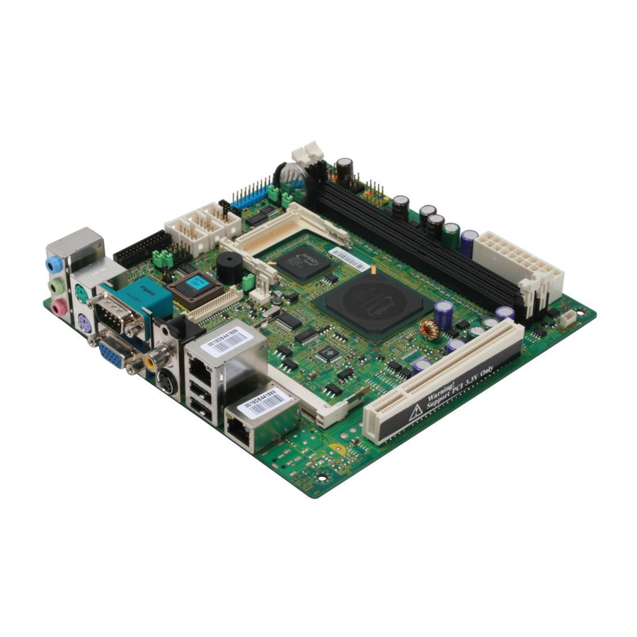
Page 14: Mainboard Layout
Bottom: USB ports JLAN1 PRJK1 (optional SKU for JPW1 DC input) (optional SKU for DC input) Fuzzy LX800 / LX800D Series (MS-9801 v1.X) Mini ITX JCF_SEL COM2 COM3 COM 4 J66EN_SEL1 AMD Geode CS5536 SYSFAN1 AMD Geode ALXD800EEXJ2VD JPWR1 (optional SKU for DC input) -
Page 15: Packing Contents
MSI motherboard User’s Guide 2 COM Ports Bracket * The pictures are for reference only. Your packing contents may vary depending on the model you purchased. MSI Driver/Utility CD Back IO Shield Getting Started Standard Cable for IDE Devices Parallel and COM Port... -
Page 16: Chapter 2 Hardware Setup
Chapter 2 Hardware Setup This chapter provides you with the information about hardware setup procedures. While doing the installation, be careful in holding the components and follow the installation procedures. For some components, if you install in the wrong orientation, the components will not work properly. -
Page 17: Quick Components Guide
MS-9801 Mainboard Quick Components Guide JLVDS1, p.2-14 JAMP1, JCI1, p.2-10 p.2-10 JAUD1, JCD1, p.2-10 p.2-14 Back Panel, p.2-7 JPWR1, PRJK1, p.2-5 p.2-4 JPW1, p.2-5 JTV1, p.2-15 J2~J7, p.2-16 COM2~4, CLR_CMOS1, p.2-13 p.2-17 JLPT1, p.2-11 p.2-11 PCI1, p.2-18 MINIPCI1, p.2-19 IDE1, p.2-9... -
Page 18: Memory
Memory The mainboard provides two 184-pin non-ECC DDR 333/400 DIMM slot and supports up to 2GB system memory. 184-pin, 2.5V Installing DDR Modules 1. The memory module has only one notch on the center and will only fit in the right orientation. -
Page 19: Power Supply
MS-9801 Mainboard Power Supply ATX 20-Pin System Power Connector: ATX1(optional SKU for ATX power) This connector allows you to connect to an ATX power supply. To connect to the ATX power supply, make sure the plug of the power supply is inserted in the proper orientation and the pins are aligned. - Page 20 4-Pin Internal Power Connector: JPW1 (optional SKU for internal DC-in) This connector allows you to connect to an internal DC12V power supply. To connect to the DC12V power supply, make sure the plug of the power supply is inserted in the proper orientation and the polarity of pins are matched.
-
Page 21: Power Consumption
MS-9801 Mainboard Power Consumption Power Supply : LEMACS Model : AX2-5300FB-2S(V) AC INPUT : 115V230V 60/50Hz 9/5A FUSE RATING : 6A/250V DC OUTPUT : 300W +5V 30A +12V 12A -5V 0.5A -12V 0.5A +5V AND +3.3V TOTAL MAX : 150W A. -
Page 22: Back Panel
Back Panel Line-In M ouse Line-Out Mic-In Keyboard Audio Port Connectors These audio connectors are used for audio devices. You can differentiate the color of the audio jacks for different audio sound effects. Blue audio jack - Line In is used for external CD player, tapeplayer or Green audio jack - Line Out, is a connector for speakers or headphones. -
Page 23: Usb Connectors
MS-9801 Mainboard LAN (RJ-45) Jacks The standard RJ-45 jacks are for connection to Local Area Network (LAN). You can connect network cables to them. LED Color 10M Cable Plug-in No Transmission Transition 100M Cable Plug-in No Transmission Transition 1000M Cable Plug-in... -
Page 24: Connectors
Connectors ATA100 Hard Disk Connector: IDE1 The mainboard has a 32-bit Enhanced PCI IDE and Ultra DMA 33/66/100 controller that provides PIO mode 0~4, Bus Master, and Ultra DMA 33/66/100 function. You can connect hard disk drives, CD-ROM and other IDE devices. The Ultra ATA100 interface boosts data transfer rates between the computer and the hard drive up to 100 megabytes (MB) per second. - Page 25 MS-9801 Mainboard Audio Amplifier Connector: JAMP1 The 5W JAMP1 is used to connect audio amplifiers to enhance audio performance. JAMP1 Front Panel Audio Connector: JAUD1 The JAUD1 front panel audio connector allows you to connect the front panel audio and is compliant with Intel ®...
- Page 26 Chassis Intrusion Switch Connector: JCI1 This connector connects to a 2-pin chassis switch. If the chassis is opened, the switch will be short. The system will record this status and show a warning message on the screen. To clear the warning, you must enter the BIOS utility and clear the record.
- Page 27 MS-9801 Mainboard Front Panel Connector: JFP1 The mainboard provides one front panel connector for electrical connection to the front panel switches and LEDs. The JFP1 is compliant with Intel Connectivity Design Guide. SIGNAL HD_LED + FP PWR/SLP HD_LED - FP PWR/SLP...
-
Page 28: Hardware Setup
Front USB Connector: F_USB1 The mainboard provides one USB 2.0 pinheader that is compliant with Intel nectivity Design Guide. USB 2.0 technology increases data transfer rate up to a maximum throughput of 480Mbps, which is 40 times faster than USB 1.1, and is ideal for connecting high-speed USB interface peripherals such as USB HDD, digital cameras, MP3 players, printers, modems and the like. - Page 29 MS-9801 Mainboard CD-In Connector: JCD1 The connector is for CD-ROM audio connector. LVDS Flat Panel Connector: JLVDS1 The LVDS (Low Voltage Differential Signal) connector provides a digital interface typically used with flat panels. After connecting an LVDS interfaced flat panel to the JLVDS1, be sure to check the panel datasheet and set the J1 LVDS Power Selection Jumper to a proper voltage.
- Page 30 TV-Out Connector: JTV1 The mainboard provides a TV-Out connector. JTV1 IrDA Infrared Module Header: IRDA1 The connector allows you to connect to IrDA Infrared module. You must configure the setting through the BIOS setup to use the IR function. IRDA1 is compliant with Intel Front Panel I/O Connectivity Design Guide.
-
Page 31: Jumpers
MS-9801 Mainboard Jumpers COM Port Power Jumpers: J2, J3, J5, J6 These jumpers specify the operation voltage of the serial port COM1~4. Pin Definition J2,J3,J5,J6 AT/ATX Power Jumper: J4 This jumper is used to select AT or ATX power. LCD Power Source Jumper: J7 This jumper is used to select the power source of LCD. - Page 32 PCI Frequency Jumper: J66EN_SEL1 This jumper is used to select the frequency of PCI bus. Clear CMOS Jumper: CLR_CMOS1 There is a CMOS RAM onboard that has a power supply from external battery to keep the data of system configuration. With the CMOS RAM, the system can automatically boot OS every time it is turned on.
-
Page 33: Slots
MS-9801 Mainboard Slots PCI (Peripheral Component Interconnect) Slot The PCI slot supports LAN cards, SCSI cards, USB cards, and other add-on cards that comply with PCI specifications. At 32 bits and 33 MHz, it yields a throughput rate of 133 MBps. -
Page 34: Mini Pci Slot
Mini PCI Slot This is a 32 bits, 33 MHz and 133 MBps PCI slot, only select the MiniPCI adapters can be installed. Installing Mini PCI Cards 1. Insert the card at an angle of 45 degrees into the Mini PCI slot, Line up the notch in the card with the small tab in the slot and slide the card into the slot until the golden finger is almost invisible. -
Page 35: Removing Mini Pci Cards
MS-9801 Mainboard Removing Mini PCI Cards If you need to remove a card in the Mini PCI slot, spread the tabs in the slot away from the notches in the card. The card should pop up slightly. Lift the card to a 45-degree angle and then gently slide the card out of the slot. -
Page 36: Chapter 3 Bios Setup
Chapter 3 BIOS Setup This chapter provides information on the BIOS Setup program and allows you to configure the system for optimum use. You may need to run the Setup program when: ² An error message appears on the screen during the system booting up, and requests you to run SETUP. -
Page 37: Entering Setup
MS-9801 Mainboard Entering Setup Power on the computer and the system will start POST (Power On Self Test) process. When the message below appears on the screen, press <DEL> key to enter Setup. Press DEL to enter SETUP If the message disappears before you respond and you still wish to enter Setup, restart the system by turning it OFF and On or pressing the RESET button. -
Page 38: Control Keys
Control Keys Move to the previous item < > Move to the next item < > Move to the item in the left hand < > Move to the item in the right hand < > <Enter> Select the item <Esc>... -
Page 39: The Main Menu
MS-9801 Mainboard The Main Menu Standard CMOS Features Use this menu for basic system configurations, such as time, date etc. Advanced BIOS Features Use this menu to setup the items of AMI Advanced Chipset Features Use this menu to change the values in the chipset registers and optimize your system’s performance. - Page 40 Set Supervisor Password Use this menu to set the password for supervisors. Set User Password Use this menu to set the password for users. Save & Exit Setup Save changes to CMOS and exit setup. Exit Without Saving Abandon all changes and exit setup. BIOS Setup...
-
Page 41: Standard Cmos Features
MS-9801 Mainboard Standard CMOS Features The items in Standard CMOS Features Menu includes some basic setup items. Use the arrow keys to highlight the item and then use the <PgUp> or <PgDn> keys to select the value you want in each item. - Page 42 Access M ode Choose the access mode forthis hard disk. Capacity Disk drive capacity(Approximated). Note that this size is usually slightly greater than the size of a formatted disk given by adisk checking program. Cylinder Set the number of cylinders for this hard disk. Head Set the number ofread/write heads.
-
Page 43: Advanced Bios Features
MS-9801 Mainboard Advanced BIOS Features Hard Disk Boot Priority Press [Enter] to enter a sub menu which shows every current hard drive installed. Use [PageUp] or [PageDown] key to select the first boot hard disk. First/Second/Third Boot Device & Boot From Other Device The items allow you to set the sequence of boot devices where BIOS attempts to load the disk operating system. - Page 44 Small Logo(EPA) Show This item enables you to show the EPA logo (brand specific graphics) on the bootup screen. Settings are: [Disabled] Shows the normal POST screen at boot. [Enabled] Shows a still image (EPA logo) on the screen at boot.ot. Chassis Intrusion Detect The field enables or disables the feature of recording the chassis intrusion status and issuing a warning message if the chassis is once opened.
-
Page 45: Advanced Chipset Features
MS-9801 Mainboard Advanced Chipset Features CPU Frequency This setting allows you to specify the CPU frequency. Memory Frequency This setting allows you to specify the memory frequency. CAS Latency This controls the timing delay (in clock cycles) before SDRAM starts a read command after receiving it. - Page 46 Resolution Specify the resolution of the monitor. Data Bus Type Select the type of Date Bus. Refresh Rate Specify the refresh rate of the monitor. HSYNC Polarity Select the active polarity of the HSYNC signal to the monitor. VSYNC Polarity Active Select the active polarity of the VSYNC signal to the monitor.
-
Page 47: Integrated Peripherals
MS-9801 Mainboard Integrated Peripherals Onboard Serial Port 1/ 2/ 3/ 4, Serial Port 3/ 4 Use IRQ Select an address and corresponding interrupt for the serial port 1/ 2/ 3/ 4. Serial Port2 Mode Select This setting allows you to specify the operation mode for serial port 2. - Page 48 Onboard Parallel Port Select an address and corresponding interrupt for the parallet port. Parallel Port Mode To operate the onboard parallel port as Standard Parallel Port only, choose [SPP]. To operate the onboard parallel port in the EPP mode simultaneously, choose [EPP]. By choosing [ECP], the onboard parallel port will operate in ECP mode only.
-
Page 49: Power Management Setup
MS-9801 Mainboard Power Management Setup ACPI Function This item is to activate the ACPI (Advanced Configuration and Power Management Interface) Function. ACPI Suspend Type This item specifies the power saving modes for ACPI function. If your operating system supports ACPI, such as Windows 2000/ XP , you can choose to enter the Standby mode in S1 or S3 fashion through the setting of this field. - Page 50 Soft-Off by PWR-BTTN When [Enabled], turning the system off with the on/off button places the system in a very low-power-usage state, with only enough circuitry receiving power to detect power button activity or Resume by Ring activity. Power-On by Alarm When you select [Enabled], fields appear that let you set the alarm that returns the system to Full On state.
-
Page 51: Pnp/Pci Configurations
MS-9801 Mainboard PNP/PCI Configurations This section describes configuring the PCI bus system and PnP (Plug & Play) feature. PCI, or Peripheral Component Interconnect, is a system which allows I/O devices to operate at speeds nearing the speed the CPU itself uses when communicating with its special components. - Page 52 IRQ Resource Press <Enter> to enter the sub-menu. IRQ 3/4/5/7/9/10/11/14/15 These items specify the bus where the specified IRQ line is used. The settings determine if AMIBIOS should remove an IRQ from the pool of avail- able IRQs passed to devices that are configurable by the system BIOS. The available IRQ pool is determined by reading the ESCD NVRAM.
-
Page 53: Load Fail-Safe / Optimized Defaults
MS-9801 Mainboard Load Fail-Safe / Optimized Defaults The two options on the main menu allow users to restore all of the BIOS settings to the default Fail-Safe or Optimized values. The Optimized Defaults are the default values set by the mainboard manufacturer specifically for optimal performance of the mainboard. -
Page 54: Set Bios Password
BIOS Setup Set BIOS Password When you select this function, a message as below will appear on the screen: Type the password, up to six characters in length, and press <Enter>. The password typed now will replace any previously set password from CMOS memory. You will be prompted to confirm the password.