Agilent Technologies 33500 Series User Manual
30 mhz function / arbitrary waveform generator
Hide thumbs
Also See for 33500 Series:
- Operating and service manual (429 pages) ,
- Service manual (166 pages)

Related Manuals for Agilent Technologies 33500 Series


Summary of Contents for Agilent Technologies 33500 Series
- Page 1 sales@artisantg.com artisantg.com (217) 352-9330 | Visit our website - Click HERE...
- Page 2 Agilent 33500 Series 30 MHz Function / Arbitrary Waveform Generator User’s Guide Agilent Technologies...
- Page 3 This product utilizes Microsoft Windows CE. Agilent highly recommends that all Windows-based computers connected to The hardware and/or software © Agilent Technologies, Inc. 2010 Windows CE instruments utilize current described in this document are fur- anti-virus software. For more information,...
- Page 4 Agilent Technologies assumes no liability of the customer’s Do Not Operate in an failure to comply with the require- Explosive Atmosphere ments.
- Page 5 If you have questions about your shipment, or if you need information about warranty, Frame or chassis service, or technical support, terminal contact Agilent Technologies: Standby supply. Unit is not completely disconnected In the United States: (800) 829- from AC mains when 4444...
- Page 6 User’s Guide Publication Number 33520-90001 (order as 33520-90000 manual set) Edition 2, September 2010 Copyright © 2010 Agilent Technologies, Inc. Agilent 33500 Series 30 MHz Function / Arbitrary Waveform Generator...
- Page 7 Agilent 33500 Series at a Glance The Agilent Technologies 33500 Series is a 30 MHz synthesized waveform generator with built-in arbitrary waveform and pulse capabilities. Its combination of bench-top and system features makes this waveform generator a versatile solution for your testing requirements now and in the future.
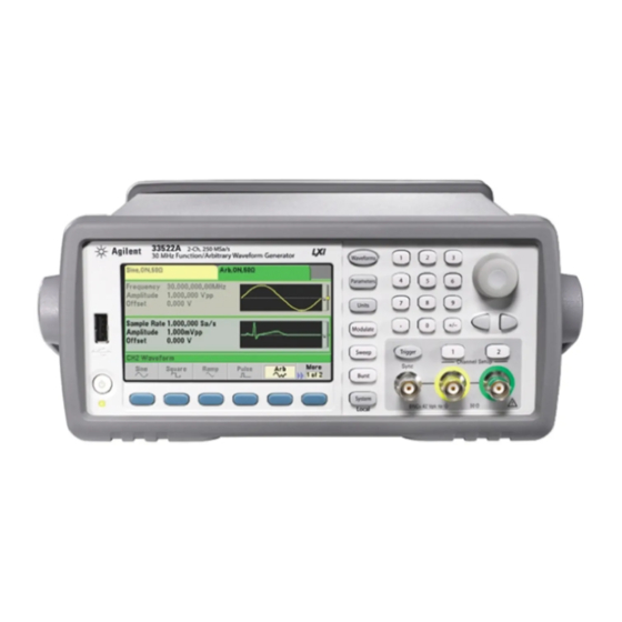
- Page 8 The Front Panel at a Glance 1 USB Port 9 System Key 2 On/Off Switch 10 Numeric Keypad 3 Channel 1 Summary Tab 11 Knob 4 Channel 2 Summary Tab 12 Cursor Keys (Arrows) 5 Waveform and Parameter Display Area 13 Manual Trigger (Sweep and Burst only) 6 Menu Operation Softkeys 14 Sync Connector...
- Page 9 The Front-Panel Display at a Glance Channel 2 Channel 1 Information Information Waveform Waveform Display Parameters Sweep or Burst Parameters Softkey Labels...
- Page 10 Front-Panel Number Entry You can enter numbers from the front-panel using one of two methods. Use the knob and cursor keys to modify the displayed number. 1. Use the keys below the knob to move the cursor left or right. 2.
- Page 11 The Rear Panel at a Glance 1 External 10 MHz Reference Input Terminal 2 Internal 10 MHz Reference Output Terminal 3 GPIB Interface Connector (option 400) 4 Chassis Ground 5 External Modulation Input Terminal 6 Input: External Trig/Gate/FSK/Burst 7 USB Interface Connector 8 Local Area Network (LAN) Connector 9 Instrument Cable Lock 10 AC Power...
- Page 12 Tutorial Chapter 5 discusses the fundamentals of signal generation and modulation techniques. Specifications Chapter 6 lists the waveform generator’s specifications. You can contact Agilent Technologies at one of the following telephone numbers for warranty, service, or technical support information. In the United States: (800) 829-4444...
-
Page 14: Table Of Contents
Contents Quick Start 15 Chapter 1 To Prepare the Waveform Generator for Use 17 To Adjust the Carrying Handle 19 To Set the Output Frequency 20 To Set the Output Amplitude 22 To Set a DC Offset Voltage 25 To Set the High-Level and Low-Level Values 27 To Output a DC Voltage 20 To Set the Duty Cycle of a Square Wave 30 To Configure a Pulse Waveform 32... - Page 15 Contents Chapter 3 Features and Functions 89 Output Configuration 92 Pulse Waveforms 110 Amplitude Modulation (AM) 114 Frequency Modulation (FM) 119 Phase Modulation (PM) 125 Frequency-Shift Keying (FSK) Modulation 130 Pulse Width Modulation (PWM) 134 Sum Modulation (Sum) 139 Frequency Sweep 143 Burst Mode 152 Triggering 161 System-Related Operations 167...
-
Page 16: Quick Start
Quick Start... - Page 17 Quick Start One of the first things you will want to do with your waveform generator is to become acquainted with the front panel. We have written the exercises in this chapter to prepare the instrument for use and help you get familiar with some of its front-panel operations.
-
Page 18: To Prepare The Waveform Generator For Use
• Agilent Automation-Ready CD (Agilent IO Libraries Suite). • USB 2.0 cable. Note: All of the 33500 Series product documentation is provided on the Agilent 33500 Series Product Reference CD that comes with the product, and is also available on the Web at www.agilent.com/find/33521A and www.agilent.com/find/33522A. - Page 19 It also prominently displays the following message: Check for error messages in the error queue. See the Agilent 33500 Series Service Guide for information on error codes, and for instructions on returning the waveform generator to Agilent for service.
-
Page 20: To Adjust The Carrying Handle
Chapter 1 Quick Start To Adjust the Carrying Handle To Adjust the Carrying Handle To adjust the position, grasp the handle by the sides and pull outward. Then, rotate the handle to the desired position. Retracted Carrying Position Extended... -
Page 21: To Set The Output Frequency
Chapter 1 Quick Start To Set the Output Frequency To Set the Output Frequency At power-on, the waveform is configured for a sine wave at 1 kHz with an amplitude of 100 mV peak-to-peak (into a 50 termination). The following steps show you how to change the frequency to 1.2 MHz. 1 Press the button, followed by the Frequency softkey. - Page 22 Chapter 1 Quick Start To Set the Output Frequency 3 Select the desired units. Press the softkey that corresponds to the desired units. When you select the units, the waveform generator outputs a waveform with the displayed frequency (if the output is enabled). For this example, press MHz.
-
Page 23: To Set The Output Amplitude
Chapter 1 Quick Start To Set the Output Amplitude To Set the Output Amplitude At power-on, the waveform generator is configured for a sine wave with an amplitude of 100 mV peak-to-peak (into a 50 termination). The following steps show you how to change the amplitude to 50 mVpp. 1 Press , then the softkey marked Amp/Offs or High/Low to make sure that you are in Amp/Offs. - Page 24 Chapter 1 Quick Start To Set the Output Amplitude 2 Enter the magnitude of the desired amplitude. Press and then press Amplitude. Using the numeric keypad, enter the number 50. 3 Select the desired units. Press the softkey that corresponds to the desired units. When you select the units, the waveform generator outputs the waveform with the displayed amplitude (if the output is enabled).
- Page 25 Chapter 1 Quick Start To Set the Output Amplitude You can easily convert the displayed amplitude from one unit to another. Simply press , and then press the Ampl As softkey and select the desired units.
-
Page 26: To Set A Dc Offset Voltage
Chapter 1 Quick Start To Set a DC Offset Voltage To Set a DC Offset Voltage At power-on, the waveform generator outputs a sine wave with a DC offset of 0 volts (into a 50 termination). The following steps show you how to change the offset to –1.5 VDC. - Page 27 Chapter 1 Quick Start To Set a DC Offset Voltage 3 Select the desired units. Press the softkey for the desired units. When you select the units, the waveform generator outputs the waveform with the displayed offset (if the output is enabled). For this example, press V. The voltage will be set as shown below.
-
Page 28: To Set The High-Level And Low-Level Values
Chapter 1 Quick Start To Set the High-Level and Low-Level Values To Set the High-Level and Low-Level Values You can specify a signal by setting its amplitude and DC offset values, as described previously. Another way to set the signal limits is to specify its high (maximum) and low (minimum) values. - Page 29 Chapter 1 Quick Start To Set the High-Level and Low-Level Values 3 Set the “High Level” value. Press the key and select High Level. Using the numeric keypad or knob and arrows, select a value of 1.0 V. (If you are using the keypad, you will need to select the V unit softkey to enter the value.) 4 Press the Low Level softkey and set the value.
-
Page 30: To Output A Dc Voltage
Chapter 1 Quick Start To Output a DC Voltage To Output a DC Voltage You can specify a constant DC voltage to be output 1 Press and then select More and DC. The Offset value becomes selected. 2 Enter the desired voltage level as an Offset. Enter 1.0 with the numeric keypad or knob and then press the V softkey if you used the keypad. -
Page 31: To Set The Duty Cycle Of A Square Wave
Chapter 1 Quick Start To Set the Duty Cycle of a Square Wave To Set the Duty Cycle of a Square Wave At power-on, the duty cycle for square waves is 50%. The duty cycle is limited by the minimum pulse width specification of 16 ns. The following steps show you how to change the duty cycle to 75%. - Page 32 Chapter 1 Quick Start To Set the Duty Cycle of a Square Wave 3 Enter the desired duty cycle. Using the numeric keypad or the knob and arrows, select a duty cycle value of “75”. If you are using the numeric keypad, press the Percent softkey to finish the entry.
-
Page 33: To Configure A Pulse Waveform
Chapter 1 Quick Start To Configure a Pulse Waveform To Configure a Pulse Waveform You can configure the waveform generator to output a pulse waveform with variable pulse width and edge time. The following steps show you how to configure a 500 ms periodic pulse waveform with a pulse width of 10 ms and edge times of 50 ns. - Page 34 Chapter 1 Quick Start To Configure a Pulse Waveform 3 Set the pulse width. Press and the Pulse Width softkey, and then set the pulse width to 10 ms. The pulse width represents the time from the 50% threshold of the rising edge to the 50% threshold of the next falling edge.
-
Page 35: To Select A Stored Arbitrary Waveform
Chapter 1 Quick Start To Select a Stored Arbitrary Waveform To Select a Stored Arbitrary Waveform There are nine built-in arbitrary waveforms stored in non-volatile memory. They are Cardiac, D-Lorentz, Exponential Fall, Exponential Rise, Gaussian, Haversine, Lorentz, Negative Ramp, and Sinc. The following steps show you how to select the built-in “exponential fall”... -
Page 36: To Use The Built-In Help System
Chapter 1 Quick Start To Use the Built-In Help System To Use the Built-In Help System The built-in help system is designed to provide context-sensitive assistance on any front-panel key or menu softkey. A list of help topics is also available to assist you with several front-panel operations. 1 View the help information for a function key. - Page 37 Chapter 1 Quick Start To Use the Built-In Help System 2 View the list of help topics. Press the button and then press Help to view the list of available help topics. To scroll through the list, press the andsoftkeys or use the knob.
- Page 38 Chapter 1 Quick Start To Use the Built-In Help System 3 View the help information for displayed messages. Whenever a limit is exceeded or any other invalid configuration is found, the waveform generator will display a message. The built-in help system provides additional information on the most recent message.
-
Page 39: To Rack Mount The Waveform Generator
Instructions and mounting hardware are included with each rack-mounting kit. Any Agilent System II instrument of the same size can be rack-mounted beside the Agilent 33500 Series. Note: Remove the carrying handle, and the front and rear rubber bumpers, before rack-mounting the instrument. - Page 40 Chapter 1 Quick Start To Rack Mount the Waveform Generator To rack mount a single instrument, order adapter kit 5063-9240. To rack mount two instruments side-by-side, order lock-link kit 5061- 8769 and flange kit 5063-9212. Be sure to use the support rails in the rack cabinet. In order to prevent overheating, do not block the flow of air into or out of the instrument.
- Page 41 Chapter 1 Quick Start To Rack Mount the Waveform Generator...
-
Page 42: Front-Panel Menu Operation
Front-Panel Menu Operation... - Page 43 Front-Panel Menu Operation This chapter introduces you to the front-panel keys and menu operation. This chapter does not give a detailed description of every front-panel key or menu operation. It does, however, give you an overview of the front- panel menus and many front-panel operations. See chapter 3 “Features and Functions,”...
-
Page 44: Front-Panel Menu Reference
Chapter 2 Front-Panel Menu Operation Front-Panel Menu Reference Front-Panel Menu Reference This section gives an overview of the front-panel menus. The remainder of this chapter contains examples of using the front-panel menus. Select a waveform • Select one of nine waveform types, including Sine, Square, Ramp, Pulse, Arbitrary, Triangle, Noise, PRBS, and DC. - Page 45 Chapter 2 Front-Panel Menu Operation Front-Panel Menu Reference Configure the parameters for modulation. • Turn modulation on or off. • Specify the modulation type. • Specify the modulation source. • Specify parameters for AM, FM, PM, PWM, BPSK, FSK and Sum modulation. Configure the parameters for frequency sweep.
- Page 46 Calibrate - Perform calibration tasks. • Set the calibration password. • Lock and unlock the instrument for calibration. • Calibrate the instrument (see Agilent 33500 Series Service Guide). Instr Setup - Configure instrument parameters. • Perform self-test. • Configure reference oscillator.
- Page 47 Chapter 2 Front-Panel Menu Operation Front-Panel Menu Reference Help - View the list of Help topics. • View the last message displayed. • View the remote command error queue. • Get help on any key. • Learn how to obtain Agilent Technical Support. •...
-
Page 48: To Select The Output Termination
To Select the Output Termination To Select the Output Termination The Agilent 33500 Series has a fixed series output impedance of 50 to the front-panel channel connectors. If the actual load impedance is different than the value specified, the displayed amplitude and offset levels will be incorrect. -
Page 49: To Reset The Waveform Generator
To reset the instrument to its factory default state, press and then select the Store/Recall and Set to Defaults softkeys. For a complete listing of the instrument’s power-on and reset conditions, see “Agilent 33500 Series Factory Default Settings” on page 216. -
Page 50: To Output A Modulated Waveform
Chapter 2 Front-Panel Menu Operation To Output a Modulated Waveform To Output a Modulated Waveform A modulated waveform consists of a carrier and a modulating waveform. In AM (amplitude modulation), the amplitude of the carrier is varied by the modulating waveform. For this example, you will output an AM waveform with 80% modulation depth. - Page 51 Chapter 2 Front-Panel Menu Operation To Output a Modulated Waveform 4 Select the modulating waveform shape. Press the Shape softkey to select the shape of the modulating waveform. For this example, select a sine wave. 5 Set the modulating frequency. Press More and then the AM Freq softkey.
-
Page 52: To Output An Fsk Waveform
Chapter 2 Front-Panel Menu Operation To Output an FSK Waveform To Output an FSK Waveform You can configure the waveform generator to “shift” its output frequency between two preset values using FSK modulation. The rate at which the shift happens is the FSK rate, and this FSK rate is determined by the internal rate generator or the signal level on the rear-panel Ext Trig connector. - Page 53 Chapter 2 Front-Panel Menu Operation To Output an FSK Waveform 3 Set the “hop” frequency. Press the Hop Freq softkey and then set the value to 500 Hz using the numeric keypad or the knob and cursor keys. If you use the numeric keypad, be sure to finish the entry by pressing the Hz softkey.
-
Page 54: To Output A Pwm Waveform
To Output a PWM Waveform You can configure the waveform generator to output a pulse width modulated (PWM) waveform. The Agilent 33500 Series provides PWM for pulse carrier waveforms. In PWM, the pulse width or duty cycle of the carrier waveform is varied according to the modulating waveform. You... - Page 55 Chapter 2 Front-Panel Menu Operation To Output a PWM Waveform 2 Select PWM. Press and choose Type, then PWM. Then press the first softkey (Modulate) to turn modulation on. Notice the status message “PWM Modulated by Sine” in the upper-left corner of the display. 3 Set the width deviation.
- Page 56 Chapter 2 Front-Panel Menu Operation To Output a PWM Waveform 4 Set the modulating frequency. Press the PWM Freq softkey and then set the value to 5 Hz using the numeric keypad or the knob and cursor keys. 5 Select the modulating waveform shape. Press the Shape softkey to select the shape of the modulating waveform.
-
Page 57: To Output A Frequency Sweep
Chapter 2 Front-Panel Menu Operation To Output a Frequency Sweep To Output a Frequency Sweep In the frequency sweep mode, the waveform generator moves from the start frequency to the stop frequency at a sweep rate which you specify. You can sweep up or down in frequency, and with either linear or logarithmic spacing, or using a list of frequencies. - Page 58 Chapter 2 Front-Panel Menu Operation To Output a Frequency Sweep 2 Select the sweep mode. Press and then verify that the linear sweep mode is currently selected on the second softkey. Press the Sweep softkey to turn sweep on. Notice the “Linear Sweep” status message at the top of the tab for the current channel.
- Page 59 Chapter 2 Front-Panel Menu Operation To Output a Frequency Sweep Note: If desired, you can press the button and then press the fourth softkey to set the frequency boundaries of the sweep using a center frequency and frequency span. These parameters are similar to the start frequency and stop frequency and are included to give you added flexibility.
-
Page 60: To Output A Burst Waveform
Chapter 2 Front-Panel Menu Operation To Output a Burst Waveform To Output a Burst Waveform You can use the waveform generator to output a waveform with a specified number of cycles, called a burst. You can control the amount of time that elapses between bursts with the internal timer or the signal level on the rear-panel Ext Trig connector. - Page 61 Chapter 2 Front-Panel Menu Operation To Output a Burst Waveform 2 Select the burst mode. Press and then press the Burst Off / On softkey. Notice that a status message “N Cycle Burst, Trig Imm” is shown in the tab of the current channel.
- Page 62 Chapter 2 Front-Panel Menu Operation To Output a Burst Waveform 4 Set the burst period. Press the Burst Period softkey and then set the period to 20 ms using the numeric keypad or the knob and cursor keys. The burst period sets the time from the start of one burst to the start of the next burst.
-
Page 63: To Trigger A Sweep Or Burst
Chapter 2 Front-Panel Menu Operation To Trigger a Sweep or Burst To Trigger a Sweep or Burst You can issue triggers from the front panel for sweeps and bursts using one of four different trigger types. • Immediate or “automatic” triggering is the default setting. In this mode, the waveform generator outputs continuously when the sweep or burst mode is selected. -
Page 64: To Store The Instrument State
Chapter 2 Front-Panel Menu Operation To Store the Instrument State To Store the Instrument State You can store instrument states in any number of state files, which always have a .sta extension. You can do this for backup purposes, or you can save your state to a USB drive and then reload the state on a different instrument in order to have instruments with matching configurations. - Page 65 Chapter 2 Front-Panel Menu Operation To Store the Instrument State • To delete a character, rotate the knob until you get to the blank character before the capital A. • To delete all characters from the cursor position to the end of the line, press teh +/- key.
-
Page 66: To Configure The Remote Interface
To Configure the Remote Interface To Configure the Remote Interface The Agilent 33500 Series supports remote interface communication using a choice of three interfaces: GPIB (optional), USB, and LAN (LXI Class C compliant). All three interfaces are “live” at power up. The following sections explain how to configure the remote interface from the instrument front panel. - Page 67 Enter when done if you are using the numeric kepad. USB Configuration The USB interface requires no front panel configuration parameters. Just connect the Agilent 33500 Series to your PC with the appropriate USB cable. The interface will configure itself. The instrument supports both USB 1.1 and USB 2.0.
- Page 68 Chapter 2 Front-Panel Menu Operation To Configure the Remote Interface LAN Configuration There are several parameters that you might need to set to establish network communication using the LAN interface. Primarily, you will need to establish an IP address. You might need to contact your network administrator for help in establishing communication with the LAN interface.
- Page 69 Chapter 2 Front-Panel Menu Operation To Configure the Remote Interface 2 Select the LAN Settings menu. Press the LAN Settings softkey. You can select Modify Settings to change the LAN settings, or you can turn LAN Services on and off or restore the LAN settings to default values.
- Page 70 Chapter 2 Front-Panel Menu Operation To Configure the Remote Interface 3 Press Modify Settings. To access most items on this screen, you must use the first softkey to switch from DHCP to Manual. With DHCP on, an IP address will automatically be set by DHCP (Dynamic Host Configuration Protocol) when you connect the instrument to the network, provided the DHCP server is found and is able to do so.
- Page 71 Chapter 2 Front-Panel Menu Operation To Configure the Remote Interface 4 Establish an “IP Setup.” If you are not using DHCP (if you have pressed the first softkey to switch DHCP to Manual), you must establish an IP setup, including an IP address, and possibly a subnet mask and gateway address.
- Page 72 Chapter 2 Front-Panel Menu Operation To Configure the Remote Interface 5 Configure the “DNS Setup” (optional). DNS (Domain Name Service) is an Internet service that translates domain names into IP addresses. Ask your network administrator whether DNS is in use, and if it is, for the host name, domain name, and DNS server address to use.
- Page 73 (0 to 255), with no leading zeros. The Agilent 33500 Series assumes that all IP addresses and other dot- notation addresses are expressed as decimal byte values, and strips all leading zeros from these byte values.
-
Page 74: To Set Up An Arbitrary Waveform
To Set up an Arbitrary Waveform To Set up an Arbitrary Waveform The Agilent 33500 Series includes an embedded waveform editor that allows you to create and edit arbitrary waveforms. You can create these waveforms by editing voltage values directly or by using any combination of up to 12 different kinds of standard waveforms. - Page 75 Chapter 2 Front-Panel Menu Operation To Set up an Arbitrary Waveform 2 Press Insert Built-in, then Choose Wave. Use the knob or the arrows below the knob to select D-Lorentz and press OK. Use the keypad and the V softkey that appears when you start typing on the keypad to set the Amplitude to 2 V, then press OK.
- Page 76 Chapter 2 Front-Panel Menu Operation To Set up an Arbitrary Waveform 4 To put the D-Lorentz waveform back, press Redo. Then press Done to exit. 5 Now we will insert a sine wave. Begin by pressing Choose Wave. Make sure Sine (the default) is highlighted, and press OK. For help in understanding the various parameters on the screen, press Parameter Help.
- Page 77 Chapter 2 Front-Panel Menu Operation To Set up an Arbitrary Waveform 6 Using the numeric keypad and the up and down arrow softkeys, set the Amplitude to 3.5 V, the Cycles to 4, and the Points to 200. Leave all other settings at their default values and press OK. 7 Notice that the first softkey, Select Point # is highlighted.
- Page 78 Chapter 2 Front-Panel Menu Operation To Set up an Arbitrary Waveform 8 Press Choose Wave, select Square and then press OK. Set the Amplitude to 3 V, the Offset to -2 V, the Cycles to 8, and the Points to 100. Press OK. Notice that the 8 square wave cycles have been inserted, beginning at the marker.
- Page 79 Chapter 2 Front-Panel Menu Operation To Set up an Arbitrary Waveform Edit Waveform Characteristics 1 Press Edit Params and then set the Sampling Rate to 100 Sa/s. Press Cycle Period and notice that it has been set to 4.08 seconds. This is because you have 408 sample points in the waveform, and the sample rate is 100 Sa/s.
- Page 80 Chapter 2 Front-Panel Menu Operation To Set up an Arbitrary Waveform 3 Press Done to exit the parameter editing screen. Press Edit Points and notice that the Point # softkey is highlighted. Enter the number 160 and press Enter to move the marker. 4 Press Voltage and change the voltage of the selected point to 4.2 V.
- Page 81 Chapter 2 Front-Panel Menu Operation To Set up an Arbitrary Waveform Zoom and Pan 1 To see the point in detail, press , then Pan/Zoom Control. Notice that the first softkey is set to Horizontal, meaning that the zooming that we are about to do will be along the horizontal (time) axis.
- Page 82 Chapter 2 Front-Panel Menu Operation To Set up an Arbitrary Waveform 3 Press Pan and set the Pan to 3 V in order to move higher on the waveform. The 4.2 V point is now clearly visible. 4 To see the entire waveform again, press Show All. Then press Done and Done again to return to the Edit Points screen.
- Page 83 Chapter 2 Front-Panel Menu Operation To Set up an Arbitrary Waveform Insert, Remove, Copy and Paste Points 1 Press Insert Point 15 times and watch the display carefully. You will see 15 new waveform points at the same voltage level. 2 Change the Point # to 220 and press Remove Point 20 times, watching the display carefully as you do so in order to see the points being removed from the waveform.
- Page 84 Chapter 2 Front-Panel Menu Operation To Set up an Arbitrary Waveform 3 You can also edit points by using a table of voltages. Press Advanced Edit and then Edit Via Table. Set Point # to 200, and then set the Voltage for point 200 to 3 V. Use the knob to move between rows and set the Voltage for points 205 and 210 to 3 V.
- Page 85 Chapter 2 Front-Panel Menu Operation To Set up an Arbitrary Waveform 5 Press Cut/Copy Paste, and set Marker 1 to 150. Then press the first softkey and change the Marker to Marker 2. Set Marker 2 to 300. The range defined by the markers is now highlighted in black. 6 Press Copy, then Paste, and then At Start.
- Page 86 Chapter 2 Front-Panel Menu Operation To Set up an Arbitrary Waveform 7 Now press Paste and At End. The same section of the waveform now also appears at the very end. 8 Now press Paste and change the Point # to 500. Then press OK, and the same portion of the waveform will be pasted in at point 500.
- Page 87 Chapter 2 Front-Panel Menu Operation To Set up an Arbitrary Waveform Perform Math The embedded waveform editor allows you to perform mathematical operations on the waveform. First you set markers to define the range of the waveform that you want to modify. You can then add, subtract or multiply that portion of the waveform by another waveform, or you can transform the waveform in ways that do not involve other waveforms.
- Page 88 Chapter 2 Front-Panel Menu Operation To Set up an Arbitrary Waveform 2 Press Add, then select Haversine and OK. Set the Amplitude to 3V, the Offset to 0 V, and press OK. Notice that the highlighted section now rises in the middle as a result of the haversine addition.
- Page 89 Chapter 2 Front-Panel Menu Operation To Set up an Arbitrary Waveform 4 Now set Marker 1 to 200 and Marker 2 to 600. 5 Press Advanced Math, select Mirror and then OK 6 Continue learning about the interface by trying other Advanced Math features, such as Invert, Absolute, Scale, and so on.
-
Page 90: Chapter 3 Features And Functions
Features and Functions... - Page 91 Features and Functions This chapter makes it easy to look up details about a particular feature of the waveform generator. It covers both front panel and remote interface operation. You may want to read chapter 2, “Front-Panel Menu Operation” first. See chapter 4, “Remote Interface Reference” for a detailed discussion of the syntax of the SCPI commands to program the waveform generator.
- Page 92 Chapter 3 Features and Functions Throughout this manual, the following conventions are used for SCPI command syntax for remote interface programming: • Square brackets ( [ ] ) indicate optional keywords or parameters. • Braces ( { } ) enclose parameters within a command string. •...
-
Page 93: Output Configuration
DC. You can also select one of nine built-in arbitrary waveforms or create your own custom waveforms. The 33500 Series includes an embedded waveform editor. You can use this editor to generate point-by-point arbitrary waveforms, which allows... - Page 94 Chapter 3 Features and Functions Output Configuration The table below shows which output functions are allowed with modulation, sweep, and burst. Each “ ” indicates a valid combination. If you change to a function that is not allowed with modulation, sweep, or burst, then the modulation or mode is turned off.
- Page 95 Chapter 3 Features and Functions Output Configuration • You may protect a device under test (DUT) by specifying upper and lower voltage limits for the waveform amplitude. • Front-Panel Operation: To select a function, press . Press (33521A) or (33522A) and then set the Output softkey to ON to output the currently selected waveform.
- Page 96 Chapter 3 Features and Functions Output Configuration Output Frequency As shown below, the output frequency range depends on the function currently selected. The default frequency is 1 kHz for all functions. Function Minimum Frequency Maximum Frequency 1 Hz Sine 30 MHz 1 Hz Square 30 MHz...
- Page 97 Chapter 3 Features and Functions Output Configuration • Front-Panel Operation: To set the output frequency, press the button, then the Frequency softkey for the selected function. Then use the knob or numeric keypad to enter the desired frequency. To set the waveform period instead, press and then press the Frequency softkey to toggle to the setting to Period.
- Page 98 Chapter 3 Features and Functions Output Configuration • You can set the output amplitude in Vpp, Vrms, or dBm. For more information, see “Output Units” on page 100. • You cannot specify the output amplitude in dBm if the output termination is currently set to “high impedance”.
- Page 99 Chapter 3 Features and Functions Output Configuration • Remote Interface Operation: VOLTage {<amplitude>|MINimum|MAXimum} Or, you can set the amplitude by specifying a high level and low level using the following commands. VOLTage:HIGH {<voltage>|MINimum|MAXimum} VOLTage:LOW {<voltage>|MINimum|MAXimum} You can also use the APPLy command to select the function, frequency, amplitude, and offset with a single command.
- Page 100 Chapter 3 Features and Functions Output Configuration • Arbitrary Waveform Limitations: For arbitrary waveforms, the maximum offset and amplitude will be limited if the waveform data points do not span the full range of the output DAC (Digital-to-Analog Converter). • You can also set the offset by specifying a high level and low level. For example, if you set the high level to +2 volts and the low level to -3 volts, the resulting amplitude is 5 Vpp (with an offset voltage of -500 mV).
- Page 101 Chapter 3 Features and Functions Output Configuration Output Units Applies to output amplitude only. At power-on, the units for output amplitude are volts peak-to-peak. • Output units: Vpp (default), Vrms, or dBm. • The unit setting is stored in volatile memory. The units are set to “Vpp”...
- Page 102 Chapter 3 Features and Functions Output Configuration Output Termination Applies to output amplitude and offset voltage only. The 33500 Series has a fixed series output impedance of 50 ohms to the front-panel channel output connectors. If the actual load impedance is different than the value specified, the displayed amplitude and offset levels will not reflect actual voltages at the load.
- Page 103 Chapter 3 Features and Functions Output Configuration • Front-Panel Operation: Press and select the Output Load softkey. Then press Set To 50 , Set To High Z, or Load. If you select Load, use the knob or numeric keypad to select the impedance.
- Page 104 Chapter 3 Features and Functions Output Configuration Duty Cycle (Square Waves) The duty cycle of a square wave represents the fraction of time per cycle that the square wave is at a high level (assuming that the waveform is not inverted). 20% Duty Cycle 80% Duty Cycle (See Pulse Waveforms, on page 110 for information about duty cycle for...
- Page 105 Chapter 3 Features and Functions Output Configuration Symmetry (Ramp Waves) Applies to ramp waves only. Symmetry represents the fraction of each cycle that the ramp wave is rising (assuming that the waveform is not inverted). 0% Symmetry 100% Symmetry • The symmetry is stored in volatile memory; the default value is 100%. •...
- Page 106 Chapter 3 Features and Functions Output Configuration Voltage Autoranging Autoranging is enabled by default and the waveform generator automatically selects the optimal settings for the attenuators. With autoranging disabled, the waveform generator uses the current attenuator settings and does not switch attenuator relays. •...
- Page 107 Chapter 3 Features and Functions Output Configuration • Remote Interface Operation: OUTPut[1|2] {OFF|ON} The APPLy command overrides the current setting and automatically enables the channel output connector. Waveform Polarity In the normal mode (default), the waveform goes positive during the first part of the cycle.
- Page 108 Chapter 3 Features and Functions Output Configuration Sync Output Signal A sync output is provided on the front-panel Sync connector. All of the standard output functions (except DC and noise) have an associated Sync signal. For applications where you may not want to output the Sync signal, you can disable the Sync connector.
- Page 109 You can change this behavior with the OUTPut[1|2]:SYNC:MODE command. • You can override normal sync behavior to force Sync to always follow the carrier waveform. The command for doing this is called OUTPut[1|2]:SYNC:MODE; see the Agilent 33500 Series Programmer’s Reference Help for details.
- Page 110 Chapter 3 Features and Functions Output Configuration • For a triggered burst, the Sync signal is a TTL “high” when the burst begins. The Sync signal is a TTL “low” at the end of the specified number of cycles (may not be the zero-crossing point if the waveform has an associated start phase).
-
Page 111: Pulse Waveforms
Chapter 3 Features and Functions Pulse Waveforms Pulse Waveforms As shown below, a pulse or square waveform consists of a period, a pulse width, a rising edge, and a falling edge. Pulse Width Trailing Edge Time Leading EdgeTime Period Period •... - Page 112 Chapter 3 Features and Functions Pulse Waveforms Pulse Width The pulse width represents the time from the 50% threshold of the rising edge of the pulse to the 50% threshold of the next falling edge. • Pulse width: 16 ns to 1,000,000 s (see restrictions below). The default pulse width is 100 µs.
- Page 113 Chapter 3 Features and Functions Pulse Waveforms Pulse Duty Cycle The pulse duty cycle is defined as: Duty Cycle = 100(Pulse Width)/Period where the pulse width represents the time from the 50% threshold of the rising edge of the pulse to the 50% threshold of the next falling edge. •...
- Page 114 Chapter 3 Features and Functions Pulse Waveforms Edge Times The edge times set the transition times for the leading and trailing edges of the pulse, either independently or together. For each transition (leading or trailing edge), the edge time represents the time between the 10% and 90% thresholds.
-
Page 115: Amplitude Modulation (Am)
5, “Tutorial.” To Select AM Modulation • The 33500 Series will allow only one modulation mode to be enabled at a time on a channel. For example, you cannot simultaneously enable AM and FM. When you enable AM, any previous modulation mode is turned off. - Page 116 Chapter 3 Features and Functions Amplitude Modulation (AM) Carrier Waveform Shape • AM carrier shape: Sine (default), Square, Pulse, Ramp, Triangle, Noise, PRBS, or Arbitrary waveform. You cannot use DC as the carrier waveform. • Front-Panel Operation: Select any waveform under except DC.
- Page 117 Chapter 3 Features and Functions Amplitude Modulation (AM) Modulating Waveform Shape The waveform generator will accept an internal or external modulation source for AM. • Modulating waveform shape (internal source): Sine (default), Square, UpRamp, DnRamp, Triangle, Noise, PRBS, or Arb waveform. •...
- Page 118 Then use the knob or numeric keypad to enter the depth. • Remote Interface Operation: AM:DEPTh {<depth_in_percent>|MINimum|MAXimum} Double Sideband Suppressed Carrier AM The 33500 Series supports two forms of amplitude modulation, “Normal” and Double Sideband Suppressed Carrier (DSSC). To change between normal AM and DSSC, use the command: [SOURce[1|2]]:AM:DSSC {ON|OFF}.
- Page 119 Chapter 3 Features and Functions Amplitude Modulation (AM) Modulating Source The waveform generator will accept an internal or external modulation source for AM. • Modulating source: Internal (default), Other Channel, or External. • If you select the External source, the carrier waveform is modulated with an external waveform.
-
Page 120: Frequency Modulation (Fm)
Chapter 3 Features and Functions Frequency Modulation (FM) Frequency Modulation (FM) A modulated waveform consists of a carrier waveform and a modulating waveform. In FM, the frequency of the carrier is varied by the instantaneous voltage of the modulating waveform. For more information on the fundamentals of Frequency Modulation, refer to chapter 5, “Tutorial.”... - Page 121 Chapter 3 Features and Functions Frequency Modulation (FM) Carrier Waveform Shape • FM carrier shape: Sine (default), Square, Pulse, Triangle, PRBS, UpRamp, DnRamp, or Noise. You cannot use arbitrary waveform or DC as the carrier waveform. • Front-Panel Operation: Press and select any waveform except Noise, Arb, or DC.
- Page 122 Chapter 3 Features and Functions Frequency Modulation (FM) Carrier Frequency The maximum carrier frequency depends on the function selected as shown below. The default is 1 kHz for all functions. Function Minimum Frequency Maximum Frequency 1 Hz 30 MHz Sine 1 Hz Square 30 MHz...
- Page 123 Chapter 3 Features and Functions Frequency Modulation (FM) Modulating Waveform Shape The waveform generator will accept an internal or external modulation source for FM. • Modulating waveform shape (internal source): Sine (default), Square, Pulse, UpRamp, DnRamp, Triangle, Noise, or PRBS. •...
- Page 124 Chapter 3 Features and Functions Frequency Modulation (FM) Modulating Waveform Frequency The waveform generator will accept an internal or external modulation source for FM. • Modulating frequency (internal source): 1 Hz to 30 MHz. The default is 10 Hz. • Front-Panel Operation: After selecting FM, press the FM Freq softkey. •...
- Page 125 Chapter 3 Features and Functions Frequency Modulation (FM) Modulating Source The waveform generator will accept an internal or external modulation source for FM. • Modulating source: Internal (default), Other Channel, or External. • If you select the External source, the carrier waveform is modulated with an external waveform.
-
Page 126: Phase Modulation (Pm)
Chapter 3 Features and Functions Phase Modulation (PM) Phase Modulation (PM) A modulated waveform consists of a carrier waveform and a modulating waveform. PM is very similar to FM, but in PM the phase of the modulated waveform is varied by the instantaneous voltage of the modulating waveform. - Page 127 Chapter 3 Features and Functions Phase Modulation (PM) Carrier Waveform Shape • PM carrier shape: Sine (default), Square, Pulse, PRBS, Ramp, or Arbitrary waveform. You cannot use Noise or DC as the carrier waveform. • Front-Panel Operation: Press and select any waveform except Noise or DC.
- Page 128 Chapter 3 Features and Functions Phase Modulation (PM) Modulating Waveform Shape The waveform generator will accept an internal or external modulation source for PM. • Modulating waveform shape (internal source): Sine (default), Square, Pulse, UpRamp, DnRamp, Triangle, Noise, or PRBS. •...
- Page 129 Chapter 3 Features and Functions Phase Modulation (PM) Modulating Waveform Frequency The waveform generator will accept an internal or external modulation source for PM. The external modulation input has a -3dB bandwidth of 100 kHz. • Modulating frequency (internal source): 1 Hz to 30 MHz. The default is 10 Hz.
- Page 130 Chapter 3 Features and Functions Phase Modulation (PM) Modulating Source The waveform generator will accept an internal or external modulation source for PM. • Modulating source: Internal (default), Other Channel, or External. • If you select the External source, the carrier waveform is modulated with an external waveform.
-
Page 131: Frequency-Shift Keying (Fsk) Modulation
Chapter 3 Features and Functions Frequency-Shift Keying (FSK) Modulation Frequency-Shift Keying (FSK) Modulation You can configure the waveform generator to “shift” its output frequency between two preset values using FSK modulation. The rate at which the output shifts between the two frequencies (called the “carrier frequency” and the “hop frequency”) is determined by the internal rate generator or the signal level on the rear-panel Ext Trig connector. - Page 132 Chapter 3 Features and Functions Frequency-Shift Keying (FSK) Modulation FSK Carrier Frequency The maximum carrier frequency depends on the function selected as shown below. The default is 1 kHz for all functions. Function Minimum Frequency Maximum Frequency 1 Hz Sine 30 MHz 1 Hz Square...
- Page 133 Chapter 3 Features and Functions Frequency-Shift Keying (FSK) Modulation FSK “Hop” Frequency The maximum alternate (or “hop”) frequency depends on the function selected as shown below. The default is 100 Hz for all functions. Function Minimum Frequency Maximum Frequency 1 Hz 30 MHz Sine 1 Hz...
- Page 134 Chapter 3 Features and Functions Frequency-Shift Keying (FSK) Modulation FSK Rate The FSK rate is the rate at which the output frequency “shifts” between the carrier frequency and the hop frequency when you select the internal FSK source. • FSK rate (internal source): 125 Hz to 1 MHz. The default is 10 Hz. •...
-
Page 135: Pulse Width Modulation (Pwm)
Chapter 3 Features and Functions Pulse Width Modulation (PWM) Pulse Width Modulation (PWM) In Pulse Width Modulation (PWM), the width of a pulse waveform is varied by the instantaneous voltage of the modulating waveform. The width of the pulse can be expressed either as a pulse width (expressed in time units, like the period) or a duty cycle (expressed as a percentage of the period). - Page 136 Chapter 3 Features and Functions Pulse Width Modulation (PWM) Modulating Waveform Shape The waveform generator will accept an internal or external modulation source for PWM. • Modulating waveform shape (internal source): Sine (default), Square, Pulse, UpRamp, DnRamp, Triangle, Noise, or PRBS. •...
- Page 137 Chapter 3 Features and Functions Pulse Width Modulation (PWM) Modulating Waveform Frequency The waveform generator will accept an internal or external modulation source for PWM. The external modulation input has a -3dB bandwidth of 100 kHz. • Modulating frequency (internal source): 1 Hz to 30 MHz. The default is 10 Hz.
- Page 138 Chapter 3 Features and Functions Pulse Width Modulation (PWM) Modulating Source The waveform generator will accept an internal or external modulation source for PM. • Modulating source: Internal (default), Other Channel, or External. • If you select the External source, the carrier waveform is modulated with an external waveform.
- Page 139 Chapter 3 Features and Functions Pulse Width Modulation (PWM) Pulse Waveform • Pulse is the only waveform shape supported for PWM. • Front-Panel Operation: Press , then Pulse. • Remote Interface Operation: FUNCtion PULSe You can also use the APPLy command to select the function, frequency, amplitude, and offset with a single command.
-
Page 140: Sum Modulation (Sum)
Chapter 3 Features and Functions Sum Modulation (Sum) Sum Modulation (Sum) In Sum Modulation (Sum), the modulating signal is added to the carrier waveform. A typical use is adding gaussian noise to a carrier signal. The waveform generator will accept an internal or external modulation source. - Page 141 Chapter 3 Features and Functions Sum Modulation (Sum) Modulating Waveform Shape The waveform generator will accept an internal or external modulation source for Sum. • Modulating waveform shape (internal source): Sine (default), Square, Pulse, UpRamp, DnRamp, Triangle, Noise, PRBS, or Arb waveform. •...
- Page 142 Chapter 3 Features and Functions Sum Modulation (Sum) Sum Amplitude The sum amplitude represents the amplitude of the signal added to the carrier (in percent of carrier amplitude). • Amplitude setting: 0 to 100% of carrier amplitude, 0.01% resolution. • The Sum Amplitude setting remains a constant fraction of the carrier amplitude and tracks carrier amplitude changes.
- Page 143 Chapter 3 Features and Functions Sum Modulation (Sum) Modulating Source The waveform generator will accept an internal or external modulation source for Sum. • Modulating source: Internal (default), Other Channel, or External. • If you select the External source, the carrier waveform is summed with an external waveform.
-
Page 144: Frequency Sweep
Chapter 3 Features and Functions Frequency Sweep Frequency Sweep In the frequency sweep mode, the waveform generator moves from the start frequency to the stop frequency at a sweep rate which you specify. You can sweep up or down in frequency, with either linear or logarithmic spacing. - Page 145 Chapter 3 Features and Functions Frequency Sweep Start Frequency and Stop Frequency The start frequency and stop frequency set the upper and lower frequency bounds for the sweep. The waveform generator begins at the start frequency, sweeps to the stop frequency, and then resets back to the start frequency.
- Page 146 Chapter 3 Features and Functions Frequency Sweep Center Frequency and Frequency Span If desired, you can set the frequency boundaries of the sweep using a center frequency and frequency span. These parameters are similar to the start frequency and stop frequency (see the previous page) and are included to give you added flexibility.
- Page 147 Chapter 3 Features and Functions Frequency Sweep Sweep Mode You can sweep with either linear or logarithmic spacing. For a linear sweep, the waveform generator varies the output frequency linearly during the sweep. For a logarithmic sweep, the waveform generator varies the output frequency logarithmically.
- Page 148 Chapter 3 Features and Functions Frequency Sweep Hold Time The hold time specifies the number of seconds to remain at the stop frequency. This allows the stop frequency to be sustained for a set time. By default, this value is zero and the sweep will immediately return to the start frequency.
- Page 149 Chapter 3 Features and Functions Frequency Sweep Marker Frequency If desired, you can set the frequency at which the signal on the front- panel Sync connector goes to a logic low during the sweep. The Sync signal always goes from low to high at the beginning of the sweep. •...
- Page 150 Chapter 3 Features and Functions Frequency Sweep Sweep Trigger Source In the sweep mode, the waveform generator outputs a single sweep when a trigger signal is received. After one sweep from the start frequency to the stop frequency, the waveform generator waits for the next trigger while outputting the start frequency.
- Page 151 Chapter 3 Features and Functions Frequency Sweep Trigger Out Signal A “trigger out” signal is provided on the rear-panel Trig Out connector (used with sweep and burst only). When enabled, a TTL-compatible square waveform with either a rising edge (default) or falling edge is output from the Trig Out connector at the beginning of the sweep.
- Page 152 Chapter 3 Features and Functions Frequency Sweep Frequency List In the frequency list mode, the function generator “steps” through the frequencies contained in a list, dwelling on each frequency for a specified period. You may also control progress through the list with the trigger system.
-
Page 153: Burst Mode
Chapter 3 Features and Functions Burst Mode Burst Mode You can configure the waveform generator to output a waveform with a specified number of cycles, called a burst. The waveform generator can produce a burst using sine, square, triangle, ramp, pulse, PRBS, or arbitrary waveforms (noise is allowed only in the gated burst mode and DC is not allowed). - Page 154 Chapter 3 Features and Functions Burst Mode Burst Mode You can use burst in one of two modes as described below. The selected mode controls the allowable trigger source that you selected, and whether certain other burst parameters apply (see the table below). •...
- Page 155 Chapter 3 Features and Functions Burst Mode • When the gated mode is selected, the burst count, burst period, and trigger source are ignored (these parameters are used for the triggered burst mode only). If a manual trigger is received, it is ignored and no error will be generated.
- Page 156 Chapter 3 Features and Functions Burst Mode Waveform Frequency The waveform frequency defines the signal frequency during the burst in the triggered and external gated modes. In the triggered mode, the number of cycles specified by the burst count is output at the waveform frequency.
- Page 157 Chapter 3 Features and Functions Burst Mode Burst Count The burst count defines the number of cycles to be output per burst. Used in the triggered burst mode only (internal or external source). • Burst count: 1 to 100,000,000 cycles, in 1 cycle increments. You can also select an infinite burst count.
- Page 158 Chapter 3 Features and Functions Burst Mode Burst Period The burst period defines time from the start of one burst to the start of the next burst. Used in the internal triggered burst mode only. Keep in mind that burst period is different than the “waveform frequency” which specifies the frequency of the bursted signal.
- Page 159 • Start phase: -360 degrees to +360 degrees. The default is 0 degrees. • From the remote interface, you can set the start phase in degrees or radians using the UNIT:ANGL command (see the Agilent 33500 Series Programmer’s Reference Help for details).
- Page 160 Chapter 3 Features and Functions Burst Mode Burst Trigger Source In the triggered burst mode, the waveform generator outputs a burst with the specified number of cycles (burst count) each time a trigger is received. After the specified number of cycles have been output, the waveform generator stops and waits for the next trigger.
- Page 161 Chapter 3 Features and Functions Burst Mode • Remote Interface Operation: [TRIGger[1|2]:]TRIGger:SOURce {IMMediate|EXTernal|TIMer|BUS} Use the following command to specify whether the waveform generator triggers on the rising or falling edge of the Ext Trig connector. [TRIGger[1|2]:]TRIGger:SLOPe {POSitive|NEGative} See “Triggering” on page 161 for more information on triggering. Trigger Out Signal A “trigger out”...
-
Page 162: Triggering
Chapter 3 Features and Functions Triggering Triggering Applies to sweep and burst only. You can issue triggers for sweeps or bursts using internal triggering, external triggering, timer triggering, or manual triggering. • Internal or “automatic” triggering is enabled when you turn on the waveform generator. - Page 163 Chapter 3 Features and Functions Triggering • The trigger source setting is stored in volatile memory; the source is set to internal trigger (front panel) or immediate (remote interface) when power has been off or after a remote interface reset. (Provided that the Power On state is set to Factory.) •...
- Page 164 Chapter 3 Features and Functions Triggering External Triggering In the external trigger mode, the waveform generator will accept a hardware trigger applied to the rear-panel Trig In connector. The waveform generator initiates one sweep or outputs one burst each time Ext Trig receives a TTL pulse with the specified edge.
- Page 165 Chapter 3 Features and Functions Triggering Software (Bus) Triggering The bus trigger mode is available only from the remote interface. This mode is similar to the manual trigger mode from the front panel, but you trigger the waveform generator by sending a bus trigger command.
- Page 166 Chapter 3 Features and Functions Triggering Trigger Input Signal This rear-panel connector is used in the following modes: • Triggered Sweep Mode: To select the external source, press the Trigger Setup softkey and then select the Source Ext softkey or execute the TRIG:SOUR EXT command from the remote interface (sweep must be enabled).
- Page 167 Chapter 3 Features and Functions Triggering Trigger Output Signal A “trigger out” signal is provided on the rear-panel Trig Out connector (used with sweep and burst only). When enabled, a TTL-compatible square waveform with either a rising edge (default) or falling edge is output from the rear-panel Trig Out connector at the beginning of the sweep or burst.
-
Page 168: System-Related Operations
Instrument State Storage There are two ways you can store and retrieve instrument states in the Agilent 33500 Series. One way is to use named state files, using either the front panel or the SCPI commands MMEMory:STORe:STATe and MMEMory:LOAD:STATe. The second way is to save states to memory locations 1 through 4 with *SAV, to retrieve states from these locations with *RCL. - Page 169 Chapter 3 Features and Functions System-Related Operations • If you delete an arbitrary waveform from non-volatile memory after storing the instrument state, the waveform data is lost and the function generator will not output the waveform when the state is recalled.
- Page 170 Error Conditions A record of up to 20 command syntax or hardware errors can be stored in the waveform generator’s error queue. See the Agilent 33500 Series Programmer’s Reference Help for a complete list of errors. • Errors are retrieved in first-in-first-out (FIFO) order. The first error returned is the first error that was stored.
- Page 171 Chapter 3 Features and Functions System-Related Operations Beeper Control Normally, the waveform generator will emit a tone when an error is generated from the front-panel or over the remote interface. You may want to disable the front-panel beeper for certain applications. •...
- Page 172 Chapter 3 Features and Functions System-Related Operations Display Brightness To optimize the readability of the front-panel display, you can adjust the brightness setting. This feature is available from the front panel only. • Display brightness: 10% to 100% (default). • The contrast setting is stored in non-volatile memory and does not change when power has been off or after a remote interface reset.
- Page 173 Browse to select the file to manage. Once you are completely prepared to execute the task, press the Perform softkey. • Remote Interface Operation: (see MEMory and MMEMory subsystems in Agilent 33500 Series Programmer’s Reference Help).
- Page 174 If the self-test fails, “Self-Test Failed” is displayed and an error number is shown. Also, one or more errors are logged to the system error queue. See the Agilent 33500 Series Service Guide for instructions on returning the instrument to Agilent for service.
- Page 175 Chapter 3 Features and Functions System-Related Operations Display Control For security reasons, or to speed up the rate at which the waveform generator can execute commands from the remote interface, you may want to turn off the front-panel display. From the remote interface, you can also display a message on the front panel.
- Page 176 Chapter 3 Features and Functions System-Related Operations • Remote Interface Operation: The following command turns off the front-panel display. DISP OFF The following command displays a message on the front panel and turns on the display if currently disabled. DISP:TEXT 'Test in Progress...' To clear the message displayed on the front panel (without changing the display state), send the following command.
- Page 177 • Remote Interface Operation: Use the following command to read the waveform generator’s firmware revision numbers. *IDN? This command returns a string in the form: Agilent Technologies,[Model Number],[10-char Serial Number], A.aa-B.bb-C.cc-DD-EE SCPI Language Version Query The waveform generator complies with the rules and conventions of the present version of SCPI (Standard Commands for Programmable Instruments).
- Page 178 Chapter 3 Features and Functions System-Related Operations License Installation (for Option 002) • The waveform generator includes has an optional feature (option 002) for extended waveform memory. Install the license for this option as follows: 1 Install the license file onto a USB drive and insert the USB drive into the instrument’s front panel.
-
Page 179: Remote Interface Configuration
• Agilent 33500 Series Product-Reference CD: This CD contains the 33500 Series instrument drivers, the Agilent Intuilink Waveform Editor software, the complete set of Agilent 33500 Series product manuals, and programming examples. The CD auto-starts and provides a Welcome page with instructions. - Page 180 LAN Configuration The following sections describe the primary LAN configuration functions that you can set from the 33500 Series front-panel Utility menu. SCPI commands are listed where applicable. In addition, there are some LAN configuration functions that can be performed only by using the SCPI commands.
- Page 181 IP address to a device on a network. DHCP is typically the easiest way to configure your Agilent 33500 Series for remote communication using the LAN interface. • Press and press the I/O Config softkey. Then press LAN Settings and Modify Settings.
- Page 182 "9". To avoid confusion, use only decimal expressions of byte values (0 to 255), with no leading zeros. For example, the 33500 Series assumes that all dot-notation addresses are expressed as decimal byte values and strips all leading zeros from these byte values.
- Page 183 Chapter 3 Features and Functions Remote Interface Configuration Subnet Mask (LAN) Subnetting allows the network administrator to divide a network into smaller networks to simplify administration and to minimize network traffic. The subnet mask indicates the portion of the host address to be used to indicate the subnet. •...
- Page 184 Chapter 3 Features and Functions Remote Interface Configuration Host Name (LAN) A host name is the host portion of the domain name, which is translated into an IP address. • The instrument is assigned a unique hostname at the factory, but you may wish to change that name.
- Page 185 Chapter 3 Features and Functions Remote Interface Configuration Domain Name (LAN) A domain name is a registered name on the Internet, which is translated into an IP address. • Front panel operation: There is no way to set the domain name from the front panel.
- Page 186 Re-selecting the LAN Settings page will display the new settings if a LAN restart took place. Additional SCPI Configuration Commands (LAN) There are some additional LAN configuration commands, not covered here, that are covered in the Agilent 33500 Series Programmer’s Reference Help.
- Page 187 Remote Interface Configuration Agilent 33500 Series Web Interface The Agilent 33500 Series provides a web interface resident in the instrument. You can use this interface over the LAN to view and modify the instrument’s I/O configuration. Also, a remote front panel interface is provided, which allows you to control the instrument over the network.
-
Page 188: External Timebase Reference
To align the phase of two Series 33500 instruments, you can use a dual- channel oscilloscope to compare the output signals: 1. Connect two 33500 Series instruments, with 10 MHz Out connected to 10 MHz In. The instrument with the more precise timebase should be used as the source of the 10 MHz reference out. - Page 189 Chapter 3 Features and Functions External Timebase Reference 4. If any of the waveform generators are multichannel (33522A), you should phase sync the two channels to each other. This operation will also synchronize each channel’s modulating waveforms to the carrier. Front panel operation: Press .
- Page 190 Chapter 3 Features and Functions External Timebase Reference See Application Note 1426: “How to Connect Two or More Signal Generators to Create a Multi-Channel Waveform Generator” provides additional information on this subject.
-
Page 191: Calibration Overview
If you forget your security code, see the Agilent 33500 Series Service Guide for more information. • The security code is set to “AT33520A” when the waveform generator is shipped from the factory. - Page 192 Chapter 3 Features and Functions Calibration Overview To Unsecure for Calibration You can unsecure the waveform generator either from the front panel or over the remote interface. The waveform generator is secured when shipped from the factory and the security code is set to “AT33520”. •...
- Page 193 Chapter 3 Features and Functions Calibration Overview To Change the Security Code To change the security code, you must first unsecure the waveform generator, and then enter a new code. Make sure you have read the security code rules described on page 190 before attempting to change the security code.
- Page 194 Chapter 3 Features and Functions Calibration Overview Calibration Message The waveform generator allows you to store one message in calibration memory in the mainframe. For example, you can store such information as the date when the last calibration was performed, the date when the next calibration is due, the waveform generator's serial number, or the name and phone number of the person to contact for a new calibration.
-
Page 195: Embedded Waveform Editor
Chapter 3 Features and Functions Embedded Waveform Editor Embedded Waveform Editor The Agilent 33500 Series includes an embedded waveform editor that allows you to create and edit arbitrary waveforms. You can create these waveforms by editing voltage values directly or by using any combination of up to 11 different kinds of standard waveforms. - Page 196 Chapter 3 Features and Functions Embedded Waveform Editor A simple DC voltage The waveform function: Sinc y = sin(x)/x The derivative of the Lorentz D-Lorentz function. The Lorentz function is y = 1/(x²+1). The D-Lorentz function, therefore is y = -2x/(x²+1)² A waveform representing a gaussian Gaussian bell curve...
- Page 197 Chapter 3 Features and Functions Embedded Waveform Editor When you select a waveform, the instrument displays a screen that allows you to specify the waveform’s parameters. These parameters include: The height of the waveform peak above 0 V when the Amplitude waveform has 0 offset.
- Page 198 Chapter 3 Features and Functions Embedded Waveform Editor The width of the gaussian bell curve between the Full Width (Gaussian only) points on the curve that are exactly one-half the bell curve's height, also called full-width half maximum. Specified as an integer from 1 to the number of data points in one cycle (default 10).
- Page 199 Chapter 3 Features and Functions Embedded Waveform Editor Basic Waveform Editing When you start the embedded waveform editor (press and Arb, then Arbs, Edit New, and Start Editor), the opening screen appears. (Note that the same menu that contains the Edit New softkey also contains an Import CSV softkey.
- Page 200 Chapter 3 Features and Functions Embedded Waveform Editor Edit Params allows you to set the waveform’s sample rate, which is the rate (in points per second) in which the waveform is played. You can specify this value as a rate or as a period. If you change one, the other will recalculate based on the number of points in the waveform.
- Page 201 Chapter 3 Features and Functions Embedded Waveform Editor Select Point # allows you to specify where the waveform is to be inserted, and the Choose Wave softkey allows you to specify which one of the 11 waveform types is to be inserted. Once you have used the arrow keys to select the waveform to insert and pressed OK, the instrument displays the parameters for the waveform to be inserted.
- Page 202 Chapter 3 Features and Functions Embedded Waveform Editor Save allows you to save the current waveform at its current location in the instrument’s internal memory. Exit Editor closes the embedded waveform editor and resumes normal front panel operation. If you have unsaved changes, the instrument produces a warning message and gives you the option of staying in the embedded waveform editor.
- Page 203 Chapter 3 Features and Functions Embedded Waveform Editor Advanced Edit As described above, the Edit Points menu includes an Advanced Edit softkey. This softkey allows you to cut, copy and paste portions of the waveform, edit waveform points in a table, and perform mathematical operations on the waveform.
- Page 204 Chapter 3 Features and Functions Embedded Waveform Editor Paste Location allows you to paste a range at the start of the waveform, the end of the waveform, or any point within the waveform. Edit Via Table allows you to edit the voltage values of individual points in a table.
- Page 205 Chapter 3 Features and Functions Embedded Waveform Editor Perform Math allows you to use markers to specify a range of the waveform. You can then add, subtract, or multiply the voltage values in that range by the voltage values in another waveform. Once you have pressed Add, Subtract, or Multiply, the instrument displays a list of waveforms.
- Page 206 Chapter 3 Features and Functions Embedded Waveform Editor When you press OK, the instrument displays a list of parameters that you can use to specify the waveform. You can also use the From Point and To Point parameters to specify the range of points on which to perform the mathematical operation.
- Page 207 Chapter 3 Features and Functions Embedded Waveform Editor Advanced Math Advanced Math allows you to perform several different types of operations on the waveform. To open Advanced Math from the embedded waveform editor, press Edit Points, Advanced Edit, Perform Math, and Advanced Math.
- Page 208 Chapter 3 Features and Functions Embedded Waveform Editor Invert reflects the waveform across the horizontal axis. Image Before Operation Image After Operation...
- Page 209 Chapter 3 Features and Functions Embedded Waveform Editor Absolute replaces all negative waveform values with their positive equivalents Image Before Operation Image After Operation...
- Page 210 Chapter 3 Features and Functions Embedded Waveform Editor Mirror reverses order of the points in the range. Image Before Operation Image After Operation...
- Page 211 Chapter 3 Features and Functions Embedded Waveform Editor Scale allows you to use amplitude and offset to scale the waveform between the points. In this example, the amplitude scale was set to 180% and the offset scale was set to 1 V. Image Before Operation Image After Operation...
- Page 212 Chapter 3 Features and Functions Embedded Waveform Editor Clip allows you to specify upper and lower limits on the waveform and changes voltage values outside those limits to be equal to the limits. In this example, the waveform was clipped to stay within the -400 mV lower limit and the 700 mV upper limit.
- Page 213 Chapter 3 Features and Functions Embedded Waveform Editor Trim allows you to use markers to “crop” the waveform so that only the points defined by the marker range remain in the waveform. Image Before Operation Image After Operation...
- Page 214 Chapter 3 Features and Functions Embedded Waveform Editor Utility Menu You can access several utility features by pressing from within the embedded waveform editor. Undo allows you to undo recent operations. The number of operations depends on the amount of available memory and the size of the undo operation.
- Page 215 Chapter 3 Features and Functions Embedded Waveform Editor Pan/Zoom Control allows you to zoom in either horizontally or vertically, using a zoom factor specified as a percentage. You can also pan (move the image) either horizontally or vertically in order to view a particular area of the waveform.
-
Page 216: Factory Default Settings
Factory Default Settings Factory Default Settings The table on the following page summarizes the factory default settings for the Agilent 33500 Series. For your convenience, this table is duplicated inside the rear cover of this manual and on the Quick Reference Card. - Page 217 Chapter 3 Features and Functions Factory Default Settings Agilent 33500 Series Factory Default Settings Output Configuration Factory Setting Function Sine wave Frequency 1 kHz Amplitude / Offset 100 mVpp / 0 VDC Output Units 50 Output Termination Autorange Modulation...
-
Page 218: Application Programs
Application Programs... -
Page 219: Introduction
(Standard Commands for Programmable Instruments) commands available to program the waveform generator. Introduction Nine example programs are included in this chapter to demonstrate controlling the Agilent 33500 Series using SCPI commands. All of these ® ® ® programs are written in Microsoft... - Page 220 Agilent has no warranty, obligations, or liability for any Sample Application Files. Agilent Technologies provides programming examples for illustration only. All sample programs assume that you are familiar with the programming language being demonstrated and the tools used to create and debug procedures.
-
Page 221: Program Listings
ROM) selects the function as “sine,” and then sets the frequency, amplitude and offset of the waveform. ' """""""""""""""""""""""""""""""""""""""""""""""""""""""""""""""""""""""" This Simple Sine program enables a simple sine wave output on channel 1 of a 33500 Series instrument with the following signal characteristics: 'Wave Shape: Sine 'Frequency:... - Page 222 Chapter 4 Application Programs Program Listings With mfIo ' Clear and reset instrument .WriteString "*CLS" .WriteString "*RST" Sleep 1000 'Send commands to set the desired configuration .WriteString "SOURCE1:FUNCTION SIN" .WriteString "SOURCE1:FREQUENCY 1000" .WriteString "SOURCE1:VOLT:UNIT VPP" .WriteString "SOURCE1:VOLT 2" .WriteString "SOURCE1:VOLT:OFFSET 0" .WriteString "OUTPUT1:LOAD 50"...
- Page 223 ' """""""""""""""""""""""""""""""""""""""""""""""""""""""""""""""""""""""" 'This Amplitude Modulation program enables an Amplitude modulation output on 'channel 1 of the 33500 Series instrument with the following signal characteristics. 'Carrier Frequency: Sine wave, 1 Mhz, 5 VPP 'Amplitude Modulated carrier with Double Sideband Suppressed Carrier...
- Page 224 Chapter 4 Application Programs Program Listings 'Enable AM Modulation .WriteString "SOURCE1:AM:STATE ON" 'Enable output .WriteString "OUTPUT1 ON" Sleep 1000 End With Text2.Text = "Amplitude modulation output enabled" Exit Sub MyError: Text2 = Err.Description Resume Next End Sub Private Sub Form_Load() Text2.Text = ""...
- Page 225 ROM) creates a linear sweep for a sine wave. It sets the start and stop frequencies, and the sweep time. ' """""""""""""""""""""""""""""""""""""""""""""""""""""""""""""""""""""""" 'This Linear Sweep program enables a simple sine sweep wave output on channel 1 'of a 33500 Series instrument with the following signal characteristics: 'Wave Shape: Sine 'Amplitude:...
- Page 226 Chapter 4 Application Programs Program Listings .WriteString "SOURCE1:SWEEP:STATE ON" 'Enable output .WriteString "OUTPUT1 ON" Sleep 1000 End With Text2.Text = "Sweep Output enabled" Exit Sub MyError: Text2 = Err.Description Resume Next End Sub Private Sub Form_Load() Text2.Text = "" End Sub...
- Page 227 ' """""""""""""""""""""""""""""""""""""""""""""""""""""""""""""""""""""""" 'This Pulse program enables a simple pulse wave output on channel 1 of a '33500 Series instrument with signal characteristics given below. A loop 'in the program increases the edge transition time by 10 nsec every 100 msec.
- Page 228 Chapter 4 Application Programs Program Listings ' Iterate over different pulse transition durations For i = 1 To 10 .WriteString "SOURCE1:FUNCtion:PULSe:TRANsition " & (i * 10) & "E-9" Sleep 100 Next i End With Text2.Text = "Pulse output with variable edge time set on Channel1" Exit Sub MyError: Text2 = Err.Description...
- Page 229 Chapter 4 Application Programs Program Listings Example: Download Arbitrary Waveform as ASCII This program (found in the “Examples\chapter6\Pulse” subdirectory on the CD-ROM) configures a pulse waveform, setting pulse width, period, and high/low levels. The edge time is then incremented. ' """""""""""""""""""""""""""""""""""""""""""""""""""""""""""""""""""""""" 'This AsciiArb program demonstrates how to download an arbitrary waveform into 'instrument volatile memory and play it back with the configuration below: 'Wave Shape:...
- Page 230 Chapter 4 Application Programs Program Listings DataStr = Join(Waveform, ",") ' Create string from data array With mFio 'Clear and reset instrument and increase the Visa Connection timeout to 40 'seconds for downloading a long waveform .WriteString "*CLS" .WriteString "*RST" .IO.Timeout = 40000 Sleep 1000 Call WaitForOPC(mFio)
- Page 231 Chapter 4 Application Programs Program Listings Text2.Text = Text2.Text & "Arb Wave output set on Channel1" & vbCrLf Exit Sub MyError: Text2 = Err.Description Resume Next End Sub Private Sub Form_Load() Text2.Text = "" End Sub Private Function WaitForOPC(mFio As VisaComLib.FormattedIO488) Dim strResult As String With mFio .WriteString "*OPC?"...
- Page 232 Chapter 4 Application Programs Program Listings Example: Sequencing This program (found in the “Examples\chapter6\PulseWidthMod” subdirectory on the CD-ROM) configures a pulse waveform with duty cycle, which is then slowly modulated by a triangle waveform. ' """""""""""""""""""""""""""""""""""""""""""""""""""""""""""""""""""""""" ' This Arb Sequence program demonstrates how to define an Arb Sequence consisting ' of one or more different arbitrary waveform segments and play it back using the ' following configuration: Wave Shape:...
- Page 233 Chapter 4 Application Programs Program Listings End With 'Loading arb files into waveform memory. With mFio .WriteString "MMEM:LOAD:DATA ""INT:\BUILTIN\SINC.ARB""" Call WaitForOPC(mFio) .WriteString "MMEM:LOAD:DATA ""INT:\BUILTIN\CARDIAC.ARB""" Call WaitForOPC(mFio) .WriteString "MMEM:LOAD:DATA ""INT:\BUILTIN\HAVERSINE.ARB""" Call WaitForOPC(mFio) End With 'Build a sequence descriptor string consisting of arbitrary waveform segments. strSeqDescriptor = "mySequence"...
- Page 234 Chapter 4 Application Programs Program Listings End Sub Private Sub Form_Load() Text2.Text = "" End Sub Private Function WaitForOPC(mFio As VisaComLib.FormattedIO488) Dim strResult As String With mFio .WriteString "*OPC?" strResult = .ReadString() End With If (InStr(strResult, "1") > 0) Then Exit Do End If Loop...
- Page 235 Chapter 4 Application Programs Program Listings Example: Two-channel Output This program (found in the “Examples\chapter6\PulseWidthMod” subdirectory on the CD-ROM) configures a pulse waveform with duty cycle, which is then slowly modulated by a triangle waveform. ' """""""""""""""""""""""""""""""""""""""""""""""""""""""""""""""""""""""" 'This 2_Channel_output program demonstrates the functionality of driving 'two different waveform outputs on the two channels of a 33522A instrument with 'following waveform characteristics.
- Page 236 Chapter 4 Application Programs Program Listings .WriteString "SOURCE2:FUNCTION SQU" .WriteString "SOURCE2:FREQUENCY 20E3" .WriteString "SOURCE2:VOLT:UNIT VRMS" .WriteString "SOURCE2:VOLT 1" .WriteString "SOURCE2:VOLT:OFFSET 1" .WriteString "OUTPUT2:LOAD MAX" 'Maximum load impedance corresponds to 10 KOhm ' Enable channel 1 output .WriteString "OUTPUT1 ON" ' Enable channel 2 output .WriteString "OUTPUT2 ON"...
- Page 237 Chapter 4 Application Programs Program Listings Example: Sine Burst with Sync This program (found in the “Examples\chapter6\PulseWidthMod” subdirectory on the CD-ROM) configures a pulse waveform with duty cycle, which is then slowly modulated by a triangle waveform. ' """""""""""""""""""""""""""""""""""""""""""""""""""""""""""""""""""""""" ' * This Sine Burst With Sync program demonstrates the synchronization of two ' * 33522A instruments.
- Page 238 Chapter 4 Application Programs Program Listings With mfIo2 .WriteString "*CLS" .WriteString "*RST" End With Sleep 2000 With mfIo1 ' Set up instrument 1 ' Send commands to set channel 1 on instrument 1 to desired configuration .WriteString "SOURCE1:FUNCTION SIN" .WriteString "SOURCE1:FREQUENCY 1000" .WriteString "SOURCE1:VOLT:UNIT VPP"...
- Page 239 Chapter 4 Application Programs Program Listings .WriteString "SOURCE1:BURST:NCYCLES INF" .WriteString "SOURCE1:BURST:MODE TRIG" .WriteString "SOURCE1:BURST:STATE ON" ' turn off continuous INIT as we are just using one trigger to start the burst .WriteString "INITiate1:CONTinuous OFF" ' arm instrument 2 with INIT so it waits for EXT trigger to start burst .WriteString "INITiate1"...
- Page 240 ' warranty, obligations or liability for any Sample Application Files. ' Agilent Technologies provides programming examples for illustration only, ' This sample program assumes that you are familiar with the programming ' language being demonstrated and the tools used to create and debug ' procedures.
- Page 241 Chapter 4 Application Programs Program Listings Amplitude: 2 Volt Peak to Peak Offset: 0 Volt Output Impedence: 50 Ohm 'Modulation: Modulation type: Sum Modulation. Sum Amplitude: Sum State: Channel1 Output: Enabled Channel2 Output: Enabled '"""""""""""""""""""""""""""""""""""""""""""""""""""""""""""""""""""""""" Private Sub Command1_Click() Dim io_mgr As VisaComLib.ResourceManager Dim mfIo As VisaComLib.FormattedIO488 Set io_mgr = New AgilentRMLib.SRMCls Set mfIo = New FormattedIO488...
- Page 242 Chapter 4 Application Programs Program Listings Exit Sub MyError: Text2 = Err.Description Resume Next End Sub Private Sub Form_Load() Text2.Text = "" End Sub...
- Page 243 Chapter 4 Application Programs Program Listings...
-
Page 244: Tutorial
Tutorial... -
Page 245: Arbitrary Waveforms
Tutorial This chapter will help you get the most from your 33500 Series waveform generator by describing certain aspects of its internal operation and the signals it generates • Arbitrary Waveforms, page 244 • Quasi-Gaussian Noise, page 246 • PRBS, page 246 •... - Page 246 If you turn filtering off, the output changes abruptly between points, with a transition time of approximately 10 ns. Waveform Sequencing The Agilent 33500 Series can assemble long, complex waveforms from smaller waveforms. The user-definable program that specifies how to do this is called a sequence, and the smaller waveforms are called segments.
-
Page 247: Quasi-Gaussian Noise
Chapter 5 Tutorial Quasi-Gaussian Noise Quasi-Gaussian Noise The Noise waveform is generated to be optimized for both quantitative and qualitative statistical properties. Though not truly random, it does not repeat for more than 50 years of continuous operation. The Noise waveform’s voltage distribution is approximately gaussian. Unlike the ideal distribution, though, there is zero probability of getting a voltage outside the range established by the instrument’s Vpp setting. - Page 248 -1. The clocking frequency of the LFSR determines the “bit rate” of the PRBS. In the 33500 Series, you can set L to be 7, 9, 11, 15, 20, or 23, resulting in sequences from 127 to 8,388,607 bits in length.
-
Page 249: Modulation
Chapter 5 Tutorial Modulation Modulation Amplitude Modulation (AM) The 33500 Series implements two forms of AM. The first form is double-sideband full-carrier (DSB-FC). DSB-FC has an ITU designation of A3E and is the type used in AM broadcasting. The second form is double-sideband suppressed-carrier (DSSC). Many modern communications systems employ DSSC on each of two carriers that have the same frequency but a 90-degree phase difference. - Page 250 Chapter 5 Tutorial Modulation The equation for DSSC is y(t)=d·m(t)·sin(ω In DSB-SC, the carrier signal is inverted whenever m(t)<0. For QAM, the second carrier signal would be cos(ω t), making it 90 degrees out of phase from the first carrier. Frequency Modulation (FM) Frequency modulation varies a carrier signal’s frequency according to the modulating signal: y(t)=A...
- Page 251 Chapter 5 Tutorial Modulation Phase Modulation (PM) PM is similar to FM, but the phase of the carrier waveform is varied, rather than the frequency: y(t)=sin[ω t+d·m(t) ] where m(t) is the modulating signal and d is the phase deviation. Frequency-Shift Keying (FSK) FSK is similar to FM, except the carrier frequency alternates between two preset values, the carrier frequency and the hop frequency.
-
Page 252: Burst
For example, you can add controlled amounts of variable-bandwidth noise to a signal or create two-tone signals. The internal modulation generator in the 33500 Series can produce the same continuous waveform as the main generator, so the Sum function lets you to create many signals that would have required two instruments before. - Page 253 Chapter 5 Tutorial Burst For bursts, the trigger source can be an external signal, an internal timer, the key, or a command received from the remote interface. The input for external trigger signals is the rear-panel Ext Trig connector. This connector accepts TTL-compatible levels and is referenced to chassis ground (not floating ground).
-
Page 254: Frequency Sweep
Chapter 5 Tutorial Frequency Sweep Frequency Sweep Frequency sweeping is similar to FM, but no modulating waveform is used. Instead, the instrument sets the output frequency based on either a linear or logarithmic function, or a list of up to 128 user-specified frequencies. -
Page 255: Attributes Of Ac Signals
Chapter 5 Tutorial Attributes of AC Signals Attributes of AC Signals The most common AC signal is a sine wave. In fact, any periodic signal can be represented as the sum of different sine waves. The magnitude of a sine wave is usually specified by its peak, peak-to-peak, or root-mean- square (RMS) value. - Page 256 Chapter 5 Tutorial Attributes of AC Signals The RMS value of a waveform also represents the one-cycle average power in the signal, minus the power in any DC component of the signal. Crest factor is the ratio of a signal’s peak value to its RMS value and will differ according to waveshape.
- Page 257 Chapter 5 Tutorial Attributes of AC Signals For a sine wave into a 50 load, the following table relates dBm to voltage. RMS Voltage Peak-to-Peak Voltage +23.98 dBm 3.54 Vrms 10.00 Vpp +13.01 dBm 1.00 Vrms 2.828 Vpp +10.00 dBm 707 mVrms 2.000 Vpp +6.99 dBm...
-
Page 258: Signal Imperfections
Chapter 5 Tutorial Signal Imperfections Signal Imperfections For sine waves, common signal imperfections are easiest to describe and observe in the frequency domain, using a spectrum analyzer. Any output signal component with a frequency different from the fundamental (or “carrier”) is considered to be distortion. Those imperfections can be categorized as harmonic distortion, non-harmonic spurious, or phase noise, and the are specified in decibels relative to the carrier level, or “dBc.”... -
Page 259: Ground Loops
Ground Loops The signal-generation portion of the 33500 Series is isolated from chassis (earth) ground. This isolation helps eliminate ground loops in your system and also allows you to reference the output signal to voltages other than ground. - Page 260 Chapter 5 Tutorial Ground Loops At frequencies above a few kHz, a coaxial cable’s shield becomes inductive, rather than resistive, and the cable begins to act like a transformer. When this happens, voltage drops in the shield due to I tend to be offset by equal voltages in the center conductor, thereby reducing the effects of ground loops at higher frequencies.
- Page 261 Chapter 5 Tutorial Ground Loops...
-
Page 262: Specifications
Specifications... - Page 263 Chapter 6 Specifications Agilent 33500 Series Function / Arbitrary Waveform Generator The characteristics and specifications shown below RAMP and TRIANGLE are a subset of the full specifications for the 33500 1 Hz to 200 kHz, 1 Hz Frequency Series waveform generators. For the complete set...
- Page 264 Chapter 6 Specifications Agilent 33500 Series Function / Arbitrary Waveform Generator OUTPUT CHARACTERISTICS ISOLATION Outputs Connector shells for Ch 1, Ch2 , Sync, and Mod In are connected together but isolated from the instrument's chassis. Maximum allowable voltage on isolated connector shells is ±42 Vpk.
- Page 265 Chapter 6 Specifications Agilent 33500 Series Function / Arbitrary Waveform Generator MODULATION TYPES AND OPERATING MODES CARRIER BPSK Burst Sweep SINE and SQUARE • • • • • • • • PULSE • • • • • • • •...
- Page 266 Chapter 6 Specifications Agilent 33500 Series Function / Arbitrary Waveform Generator MODULATION CHARACTERISTICS SWEEP AMPLITUDE MODULATION (AM) Type Linear, Logarithmic, List (up to 128 user-defined frequencies) Source Internal or External, or either channel with 33522A Operation Linear and Logarithmic sweeps are...
- Page 267 Chapter 6 Specifications Agilent 33500 Series Function / Arbitrary Waveform Generator SYNC / MARKER OUTPUT FREQUENCY REFERENCE OUTPUT Connector Front-panel BNC, isolated from Connector Rear-panel BNC, chassis- chassis referenced Functions Sync, Sweep Marker, Burst Output 50 Ω, AC-coupled Marker, or Arbitrary Waveform...
- Page 268 Chapter 6 Specifications Agilent 33500 Series Function / Arbitrary Waveform Generator MEMORY ENVIRONMENTAL ARBITRARY WAVEFORM MEMORY Storage -40˚ C to 70˚C Temperature Volatile 1M samples / ch 512 Sequence steps / ch Warm-Up Time 1 hour Optional 16M point / ch Operating EN61010, Pollution Degree 2;...
- Page 269 Chapter 6 Specifications Agilent 33500 Series Function / Arbitrary Waveform Generator Product Dimensions All dimensions are shown in millimeters.
-
Page 270: Index
Index If you have questions relating to the operation of the Agilent 33500 Series, call 1-800-829-4444 in the United States, or contact your nearest Agilent Technologies Office. Numerics carrier frequency 115 starting phase 251 10 MHz In connector 187 carrier waveform 115... - Page 271 Index USB 65, 66, 178 deviation (FM) 123 FM 124 connector DHCP 70 FSK 133 10 MHz In 187 DHCP On/Off 180 PM 129, 137 10 MHz Out 187 digits separator 175 PWM 142 Modulation In 118, 124, dimensions external timebase 187 133, 142 product 268 external trigger 163...
- Page 272 Index sweep time 141, 146, Sync signal 145 frequency-shift keying gated burst 153, 252 frequency deviation (FM) See FSK 51 gateway address 182 see FSK GPIB frequency modulation front panel address 65, 178, 179 carrier frequency 121 connectors 7 configuration 65 carrier waveform 120 display overview 8 connector 10...
- Page 273 Index front-panel configura- tion 65 MAC address 185 setting address 65 Configuration 179 manage files 172 impedance configuration 185 manual trigger 162 effect on amplitude 101 connector 10 marker frequency 148 impedance, load 47 DHCP 180 menu operation 41 instrument errors 169 DNS server 184 message instrument overview 6...
- Page 274 Index duty cycle limitations 95 (FM) 123 naming stored states front-panel selection 20 peak voltage 254 front-panel operation 63 function limitations 95 peak-to-peak voltage 254 n-cycle burst 251 output function percent modulation (AM) new folder 172 allowed with modula- number entry 9 tion 92 period number keypad 9...
- Page 275 Index phase deviation 128, 136 security polarity 106 rack mounting kits 39 calibration 190 polarity, waveform 106 ramp waveform self test 171, 174 power connector 10 symmetry 104 self-test 173 power cord 17 range hold, amplitude 105 setting address power switch 17 rear panel LAN 67 product dimensions 268...
- Page 276 Index support, technical 11 system time 171 trigger slope sweep 143 burst 159 center frequency 145 sweep 149 external trigger source technical support 11 triggering phone numbers 3 burst 160 frequency span 145 Web site 3 external source 163 front-panel operation temperature overload 39 front-panel operation 62...
- Page 277 Index version, SCPI 176 voltage autorange 105 voltage overload 105 voltage units 100 vpp 100 vrms 100 warranty 2 waveform invert 106 waveform output connector 105 enable/disable 105 polarity 106 waveform polarity 106 waveform tutorial 243 interface 186...