Advertisement
Available languages
Available languages
Quick Links
General information:
The BVE/BVS series of Bi-directional Ball valves
are designed for general use in isolating suction,
discharge
and
liquid
line
maintenance shutdown periods.
• For further information, see technical data sheet
BVE_35066.
!
Safety instructions:
• Read
installation
instructions
Failure to comply can result in device failure,
system damage or personal injury.
• It is intended for use by persons having the
appropriate
knowledge
attempting to install the valve, make sure
pressure in system is brought to and remains at
atmospheric pressure.
• Do not release any refrigerant into the
atmosphere.
• Do not use any other fluid media without prior
approval of Emerson. Use of fluid not listed
could result in change of hazard category of
product and consequently change of conformity
assessment
requirement
accordance with European pressure equipment
directive 97/23/EC
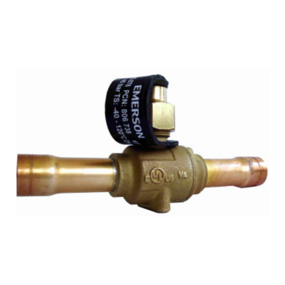
• The attached strap (Fig. 3) contains important
valve data. Do not remove because of warranty
and traceability reasons.
• Do not connect on BVS Schrader connection
any safety pressure switches or other control
devices
Technical Data
Type:
Connection, DN
Max. working pressure PS
Medium temperature TS
Fluid group acc. PED
Refrigerant:
Material
Hazard category: PED 97/23/EC
Marking
BVE__65155__R06.docx
Ball Valves Series BVE / BVS
Mounting location:
Mounting location:
•
• The BVE/BVS valve may be installed in any
position which allows access to remove the stem
pipe-work
during
cap. The valves are bi-directional.
•
• Locate the BVE/BVS as close as possible to the
section of pipe-work to be isolated. This will reduce
the amount of refrigerant to be recovered during
future maintenance of the system.
Installation:
Installation:
•
• Do not remove seal caps until ready for
thoroughly.
installation. The seal caps should be removed with
care to avoid damaging the connections.
•
• For BVS version do not mount schraeder valve
and cap before brazing.
and
skill.
Before
•
• Ensure valve is in the fully open position before
brazing (see Fig. 2a). Failure to do so could cause
damage to internal components.
•
• To avoid oxidization, it is advised to purge the
system with an inert gas such as nitrogen while
brazing.
• When brazing, direct the flame away from the
•
main body of the valve to avoid possible internal
damage. Use wet rags or other suitable heat
protection (see Fig. 1). On larger body sizes it may
for
product
in
be necessary to re-humidify wet rags with
additional water during brazing process!
•
To avoid overheating the valve body, it is advised to
make the joint at one end and cool the valve
completely before repeating the procedure on the
other end connection.
•
For BVS version install schraeder valve and
schraeder valve cap after cooling down of the ball
valve.
•
For panel mounting see dimension of holes in Fig. 4.
BVE- / BVS-... ≤ ≤ ≤ ≤ 28 mm
28 mm
1/4" (6mm) ... 1-1/8" (28mm)
1/8" (28mm)
–40°C ... +120°C (short term +150° C)
(short term +150° C) / –40°F ... +250°F (short term +300° F)
HCFC, HFC, CO
HCFC, HFC
not applicable
not applicable
UL 207 ,
Replacement for R05
Operating Instructions
BVE- / BVS-...> 32 mm
1-3/8" (35mm) ... 2-5/8" (67mm)
45 bar / 650 psig
II
(ASHRAE Standard 34: A1, A2)
2
CW617N
I
, UL 207,
Date: 18.04.2011
GB
Leakage test:
Leakage test:
• After completion of installation, a test pressure
After completion of installation, a test pressure
must be carried out as follows:
must be carried out as follows:
- According to EN378 for systems which must
According to EN378 for systems which must
comply
comply
with
with
European
European
pressure
pressure
directive 97/23/EC.
directive
- To maximum working pressure of system for
maximum working pressure of system for
other applications
other applications
Warning:
: Failure to do so could result in loss of
refrigerant.
refrigerant.
Operation:
Operation:
• The Valve has a built
The Valve has a built-in stop for the stem and
opening/closing of the valve is clearly indicated as
opening/closing of the valve is clearly indicated as
shown in Fig. 3. Open Valve is shown in Fig. 2a
shown in Fig. 3. Open Va
and closed valve in Fig. 2b.
and closed valve in Fig. 2b.
• Never leave the ball position as shown in Fig. 2c
Never leave the ball position as shown in Fig. 2c
otherwise seat leakage can occur
otherwise seat leakage can occur.
• To avoid operation by unauthorized person's valve
To avoid operation by unauthorized person's valve
can be equipped with a seal
can be equipped with a sealable cap which is
available as
available as accessory (see fig. 5).
• The plastic cap is equipped with an O
The plastic cap is equipped with an O-Ring. Do
not use any tool to mount the cap. Cap must be
not use any tool to mount the cap. Cap must be
closed hand tight
hand tight only.
If the valve is installed in hot gas
Warning:
discharge line, the valve has hot surface temperature
discharge line, the valve has hot surface temperature
during operation of syst
during operation of system or short after off-cycle.
• The Design pressure marked on this component shall not
The Design pressure marked on this component shall not
be less than the installed system working pressure or less
be less than the installed system working pressure or less
than the values outlined in ANSI/ASHARE 15 for the
than the values outlined in ANSI/ASHARE 15 for the
charges refrigerant. After charging mark the installed
charges refrigerant. After charging mark the installed
equipment with the refrigerant type and Oil used.
nt with the refrigerant type and Oil used.
• For use with HFC and HCFC refrigerant listed in
For use with HFC and HCFC refrigerant listed in
CAN/CSA
CAN/CSA
B52,
B52,
ANSI/ASHARE
ANSI/ASHARE
ANSI/ASHARE 15 SEC. 9.2. Where the saturation
ANSI/ASHARE 15 SEC. 9.2. Where the saturation
pressure at 125°F (High side) and 80°F (Low side) is less
pressure at 125°F (High side) and 80°F (Low side) is less
than the maximum design Worki
than the maximum design Working Pressure. After
charging mark Unit with refrigerant type and oil type.
charging mark Unit with refrigerant type and oil type.
US
equipment
equipment
34
34
and
and
PCN 864 091
Advertisement

Related Manuals for Emerson BVE Series


Summary of Contents for Emerson BVE Series
- Page 1 (see fig. 5). • • When brazing, direct the flame away from the approval of Emerson. Use of fluid not listed • The plastic cap is equipped with an O The plastic cap is equipped with an O-Ring. Do...
- Page 2 • Zur Vermeidung von Oxidation Ventil mit abgelassen werden! anschlag anschlag zur klaren Anzeige eines vollständig Schutzgas (z.B. Stickstoff) einlöten. • Es dürfen nur von Emerson freigegebene geschlossenen lossenen/offenen Ventils gemäß Fig. 3. • • Ventil beim Einlöten mit einem nassen Tuch Kältemittel eingesetzt werden.
- Page 3 L'utilisation d'un fluide non (v. Fig. 5) (v. Fig. 5). l’azote. approuvé peut conduire à une non conformité • Le capuchon plastique est équipé d'un joint Le capuchon plastique est équipé...
- Page 4 • Para evitar la manipulación inadecuada de la Para evitar la manipulación inadecuada de la soldadura. previamente aprobado por Emerson. El uso de válvula, esta puede ser suministrada con un tapón válvula, esta puede ser suministrada con un tapón •...
- Page 5 Disattenzioni potrebbero causare il danneggiamento • La valvola ha un fermo interno per lo stelo e La valvola ha un fermo interno per lo stelo e espressamente approvate dalla Emerson. L’uso dei componenti interni. l’apertura/chiusura della valvola sono indicate l’apertura/chiusura della valvola sono indicate di refrigeranti non indicati nelle specifiche •...
- Page 6 In Fig. 3. gemarkeert als aangegeven In Fig. 3. Open geheel geopende stand ingesoldeerd worden. • Er mogen alleen door Emerson vrijgegeven afsluiter is weergegeven in Fig. 2a en een gesloten afsluiter is weergegeven in Fig. 2a en een gesloten •...
- Page 7 BVE / BVS uzavírací ventily Návod k montáži • Nesprávné provedení zkoušek m Nesprávné provedení zkoušek může způsobit Základní údaje Montážní p Montážní poloha poranění osob a poškození díl ění osob a poškození dílů zařízení Kulové ventily BVE/BVS jsou určeny k uzavírání •...
- Page 8 • Nie uwywać czynników innych ni zatwierdzone wystąpienie nieszczelno ąpienie nieszczelności w gniaździe zaworu. obojętnym takim jak azot. przez Emerson. U ycie niezatwierdzonych • Aby unikn Aby uniknąć ekploatacji przez osoby niepowołane, • • Aby...
- Page 9 • • . 3. • • . 2a, . 2b. . 2a). • • . 2c, • • • • Emerson. • • . 5). • 97/23/ • . 3) . 1). • • • • • • . 4.
- Page 10 球阀 球阀 球阀 中文 中文 BVE/BVS系列 中文 中文 系列球阀 系列 系列 BVE/BVS • • BVE/BVS • EN378 EN378 • BVE_35066. • • BVE/BVS 97/23/EC • • • • • • • • • • • • • 97/23/EC • • •...
- Page 11 B VE / BVS ボ ボ ボ ボ ボ ボ ボ ボ ボ ボ ボ ボ ボ ボ ボ ボ ボ ボ ボ ボ ボ ボ ボ ボ シ シ シ シ シ シ シ シ シ シ シ シ シ シ シ シ 取...
- Page 12 1-1/8 ... 1-3/8 806 771 > 1-3/8 806 772 Europe: Emerson Electric GmbH & Co OHG - Postfach Postfach 1251 - Heerstraße 111 - D-71332 Waiblingen/Germany - P Phone .49-(0)7151-509-0 - Fax -509-200 www.emersonclimate.eu USA: Emerson Climate Technologies - 11911 Adie Road 11911 Adie Road - PO Box 411400 - St.