Table of Contents
Advertisement
Quick Links
Advertisement
Table of Contents

Related Manuals for Acer Veriton X680G


Summary of Contents for Acer Veriton X680G
- Page 1 Acer Veriton X680G/X688G/X680 Service Guide PRINTED IN TAIWAN...
-
Page 2: Revision History
Revision History Please refer to the table below for the updates made on this service guide. Date Chapter Updates... - Page 3 Copyright Copyright © 2010 by Acer Incorporated. All rights reserved. No part of this publication may be reproduced, transmitted, transcribed, stored in a retrieval system, or translated into any language or computer language, in any form or by any means, electronic, mechanical, magnetic, optical, chemical, manual or otherwise, without...
- Page 4 Any Acer Incorporated software described in this manual is sold or licensed "as is". Should the programs prove defective following their purchase, the buyer (and not Acer Incorporated, its distributor, or its dealer) assumes the entire cost of all necessary servicing, repair, and any incidental or consequential damages resulting from any defect in the software.
- Page 5 Conventions The following conventions are used in this manual: SCREEN MESSAGES NOTE WARNING CAUTION IMPORTANT Denotes actual messages that appear on screen. Gives additional information related to the current topic. Alerts you to any physical risk or system damage that might result from doing or not doing specific actions.
-
Page 6: Fru Information
Service Guide. For ACER-AUTHORIZED SERVICE PROVIDERS, your Acer office may have a DIFFERENT part number code to those given in the FRU list of this printed Service Guide. You MUST use the list provided by your regional Acer office to order FRU parts for repair and service of customer machines. -
Page 7: Table Of Contents
System Check Procedures Power System Check System External Inspection System Internal Inspection Beep Codes Checkpoints BIOS Recovery Jumper and Connector Information M/B Placement Jumper Setting Setting Jumper FRU (Field Replaceable Unit) List Veriton X680G/X688G/X680 Exploded Diagram Veriton X680G/X688G/X680 FRU List... -
Page 8: System Tour
System Tour Features Below is a brief summary of the computer’s many feature: NOTE: The features listed in this section is for your reference only. The exact configuration of the system depends on the model purchased. Operating System Microsoft Windows7 Home Basic •... -
Page 9: Hard Disk
One earphone and one microphone jack is required on front bezel. • 3 HD audio plugs on rear panel. • Auto detection and re-tasking behavior is following Acer Audio Jack spec. • MAC Controller:Q57. • PHY: Intel Hanksville-D 82578 PCI-E Giga LAN. - Page 10 4 ports for front daughter board • 4 ports reserved • Connector Pin: standard Intel FPIO pin definition. • Data transfer rate support:USB 2.0/1.1 • All USB ports must be boot-capable includes USB-ODD, USB-HDD, USB-FDD, and etc… • All USB ports must provide the over current protection. •...
-
Page 11: System Bios
Color management for on board connecter (please refer to Acer spec). • Header Naming should follow MB Header Naming (Refer to Appendix). • Braidwood connector (reserved). • One 3pin ME enable/disable connector (with 1 jumper). • System BIOS Use SPI Flash •... -
Page 12: Block Diagram
Block Diagram Chapter 1... -
Page 13: System Components
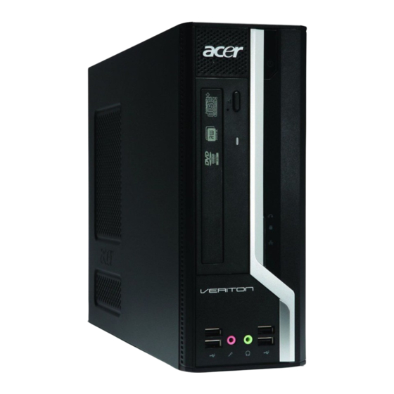
System Components This section is a virtual tour of the system’s interior and exterior components. Front Panel Component Acer logo Optical drive button ODD activity indicator Optical drive USB 2.0 ports Microphone-in jack Headphone/Speaker-out/line-out jack CF I/II (CompactFlash Type I/II) slot... -
Page 14: Rear Panel
Rear Panel Component Fan aperture PS2 keyboard connector DVI port COM port e-SATA port USB 2.0 ports Microphone/speaker-out/line-in jack Expansion slot(graphics card and modem card) Line-out jack Line-in jack RJ45 LAN port D-sub port PS2 mouse connector Power connector Chapter 1... -
Page 15: Hardware Specifications And Configurations
Hardware Specifications and Configurations Processor Item Specification Type Intel Lynnfield/Clarkdale DMI/FDI 1333 MHz CPUs Socket Intel Socket T LGA 1156 pin 1333 MHz Minimum operating speed 0 MHz (If Stop CPU Clock in Sleep State in BIOS Setup is set to Enabled.) BIOS Item BIOS code programmer... -
Page 16: Memory Combinations
Memory Combinations Slot Memory Slot 1 1GB, 2GB,4GB Slot 2 1GB, 2GB,4GB Slot 3 1GB, 2GB,4GB Slot 4 1GB, 2GB,4GB Maximum System Memory Supported System Memory Item Memory slot number Support Memory size per socket Support memory type Support memory interface Support memory voltage Support to parity check feature Support to error correction code (ECC) feature No... -
Page 17: Sata Interface
SATA Interface Item SATA controller SATA controller resident bus Number of SATA channel Support bootable CD-ROM USB Port Item Universal HCI USB Class USB Connectors Quantity Environmental Requirements Item Specification Temperature Operating +5°C ~ +35°C Non-operating -20 ~ +60°C (Storage package) Humidity Operating 15% to 80% RH... -
Page 18: Power Management Function(Acpi Support Function)
Power Management Function(ACPI support function) Device Standby Mode Independent power management timer for hard disk drive devices(0-15 minutes,time step=1minute). • Hard Disk drive goes into Standby mode(for ATA standard interface). • Disable V-sync to control the VESA DPMS monitor. • Resume method:device activated (keyboard for DOS, keyboard &mouse for Windows. -
Page 19: System Utilities
System Utilities CMOS Setup Utility CMOS setup is a hardware configuration program built into the system ROM, called the complementary metal- oxide semiconductor (CMOS) Setup Utility. Since most systems are already properly configured and optimized, there is no need to run this utility. You will need to run this utility under the following conditions. When changing the system configuration settings •... -
Page 20: Entering Cmos Setup
Entering CMOS setup Turn on the server and the monitor. If the server is already turned on, close all open applications, then restart the server. During POST, press Delete. If you fail to press Delete before POST is completed, you will need to restart the server. The Setup Main menu will be displayed showing the Setup’s menu bar. -
Page 21: Setup Utility Menus
Setup Utility Menus The Setup Main menu includes the following main setup categories. Parameter Description Product Information This page shows the relevant information of the main board Standard CMOS Features This setup page includes all the items in standard compatible BIOS Advanced Chipset Features This setup page includes all the items of Award special enhanced features Advanced Chipset Features... -
Page 22: Product Information
Product Information The Product Information menu displays basic information about the system. These entries are for your reference only and are not user-configurable. Parameter Description Processor Type Type of CPU installed on the system. Processor Speed Speed of the CPU installed on the system. System Memory Total size of system memory installed on the system. -
Page 23: Standard Cmos Features
Standard CMOS Features Parameter Description System Date Set the date following the weekday-month-day-year format. System Time Set the system time following the hour-minute-second format. AHCI Port 1/2/3/4 Press Enter to view detailed device information connected to the SATA connectors. Halt On Determines whether the system will stop for an error during the POST. -
Page 24: Advanced Bios Feature
Advanced BIOS Feature Parameter Description Quick Boot Allows you to decrease the time it takes to boot the computer by shortening or skipping certain standard booting process. Quiet Boot When enabled, the BIOS splash screen displays during startup. When disabled, the diagnostic screen displays during startup. 1st/2nd/3rd/4th Boot Device Specifies the boot order from the available devices. -
Page 25: Advanced Chipset Features
Advanced Chipset Features Parameter Description Intel EIST When enabled, this feature allows the OS to reduce power consumption. When disabled, the system operates at maximum CPU speed. Intel XD Bit When enabled, the processor disables code execution when a worm attempts to insert a code in the buffer preventing damage and worm propagation. -
Page 26: Integrated Peripherals
Integrated Peripherals Parameter Description Onboard SATA Controller Enables or disables the onboard SATA controller. Onboard SATA Mode Select an operating mode for the onboard SATA. Onboard USB Controller Enables or disables the onboard USB controller. Legacy USB Support Enables or disables support for legacy USB devices. USB Storage Emulation If Auto, USB device equal or less than 2GB will be emulated as Floppy and remaining as harddrive. -
Page 27: Power Management Setup
Power Management Setup Parameter Description ACPI Aware O/S This item supports ACPI (Advanced Configuration and Power management Interface).Usethis item to enable or disable the ACPI feature. ACPI Suspend Mode Select an ACPI state. Deep Power Off Mode If Enabled, it will support EUP Lot6 Function. If Disabled, it will not support EUP Lot6Function. -
Page 28: Pc Health Status
PC Health Status Parameter Description System Shutdown Enable you to set the maximum temperature the syetem can reach Temperture before powering down. CPU Shutdown Temperture Enable you to set the maximum temperature the CPU can reach before powering down. Smart FAN Enables or disables the smart system fan control function. - Page 29 Frequency/Voltage Control Parameter Description Enabled Clock to All DIMM/ If enabled, whatever the slot has been inserted or not, clock will be PCI/PCIE sent. Disable clock toempty DIMM/PCI/PCIE slots if option is disabled. Spread Spectrum Enables or disables the reduction of the mainboard’s EMI. Note: Remember to disable the Spread Spectrum feature if you are overclocking.
-
Page 30: Bios Security Features
BIOS Security Features Parameter Description Supervisor Password This item indicates whether a supervisor password has been set. If the password has beeninstalled, Installed displays. If not, Not Installed displays. User Password This item indicates whether a user password has been set. If the password has been installed,Installed displays. -
Page 31: Load Default Settings
Load Default Settings The Load Default Settings menu allows you to load the default settings for all BIOS setup parameters. Setup defaults are quite demanding in terms of resources consumption. If you are using low-speed memory chips or other kinds of low-performance components and you choose to load these settings, the system might not function properly. - Page 32 Save & Exit Setup The Save & Exit Setup menu allows you to save changes made and close the Setup Utility. Chapter 2...
-
Page 33: Exit Without Saving
Exit Without Saving The Exit Without Saving menu allows you to discard changes made and close the Setup Utility. Chapter 2... -
Page 34: System Disassembly
System Disassembly This chapter contains step-by-step procedures on how to disassemble the desktop computer for maintenance and troubleshooting. Disassembly Requirements To disassemble the computer, you need the following tools: Wrist grounding strap and conductive mat for preventing electrostatic discharge • Flat-blade screwdriver •... -
Page 35: Pre-Disassembly Procedure
Pre-disassembly Procedure Before proceeding with the disassembly procedure, perform the steps listed below: Turn off the system and all the peripherals connected to it. Unplug the power cord from the power outlets. Unplug the power cord from the system. Unplug all peripheral cables from the system. Place the system unit on a flat, stable surface. -
Page 36: Removing The Side Panel
Removing the Side Panel Remove the three screws located on the rear edge of the side panel. Slide the side panel toward the back of the chassis until the tabs on the cover disengage with the slots on the chassis. Lift the side panel away from the server and put it aside for reinstallation later. -
Page 37: Removing The Front Bezel
Removing the Front Bezel Release the front bezel from the chassis interior. Pull the bezel away from the chassis. Chapter 3... -
Page 38: Removing The Heat Sink Fan Assembly
Removing the Heat Sink Fan Assembly WARNING:The heat sink becomes very hot when the system is on. NEVER touch the heat sink with any metal or with your hands. Use a long-nosed screwdriver to loosen the four screws on the heat sink, in the order as shown below. Lift the heat sink fan assembly away from the mainboard. -
Page 39: Removing The Processor
Removing the Processor IMPORTANT:Before removing a processor from the mainboard, make sure to create a backup file of all important data. Release the load lever. Lift the load lever and load plate to the fully open, upright position (1) and (2). Pull out the processor from the socket. -
Page 40: Removing The Optical Drive
Removing the Optical Drive Disconnect the data and power cables from the rear of the optical drive. Slide lock handle toward the right until the lock handle no removing as show below. Pull the drive out of the drive bay. Chapter 3... -
Page 41: Removing The Hard Disk Drive
Removing the Hard Disk Drive Disconnect the data and power cables from the rear of the hard drive. Disconnect the other end of the data cable(HDD and ODD) from the mainboard. Remove the HDD-ODD bracket. Remove the screw that secures the HDD bracket to the chassis. Chapter 3... - Page 42 Remove the two screw from chassis. Lift the bracket up and turn it over. Place the bracket on a clean, static-free work surface. Use two fingers to press the HDD bracket then pull the bracket up. Chapter 3...
- Page 43 Take out the HDD module Use a hand to open out the HDD bracket until the hook of HDD bracket away from the HDD screw bore. then use other hand to take out the HDD module. Chapter 3...
-
Page 44: Removing The Power Supply
Removing the Power Supply Disconnect the 4-pin and 24-pin power supply cables from the mainboard. Remove the screw that secures the power supply to the chassis. Remove the two screws that secure the power supply to the rear panel. Remove the four screws that secures the power supply to the chassis. Chapter 3... - Page 45 Lift the power supply module out of the chassis. Chapter 3...
-
Page 46: Removing The Vga Card
Removing the VGA Card Remove the screw that secures the card to the chassis. Press the clip toward under. Gently pull the card to remove it from the mainboard. Chapter 3... -
Page 47: Removing The Memory Modules
Removing the Memory Modules IMPORTANT:Before removing any DIMM from the memory board, make sure to create a backup file of all important data. Press the holding clips on both sides of the DIMM slot outward to release the DIMM(1). Gently pull the DIMM upward to pull it away from the M/B(2). Chapter 3... -
Page 48: Removing The Front I/O And Card Reader Boards
Removing the Front I/O and Card Reader Boards Disconnector the the USB and audio cables from the mainboard. Open the cable retention clip,then take out these cables. Removing the screw from chassis. Chapter 3... - Page 49 Pull the front I/O and USB assembly from chassis. Chapter 3...
-
Page 50: Removing The Intrusion Alarm Cable
Removing the Intrusion Alarm Cable Disconnector the intrusion alarm from the motherboard. Removing the intrusion alarm assembly. Removing the two screws from the chassis. Release the intrusion alarm assembly from the chassis. Chapter 3... -
Page 51: Removing The Power Switch,Obr And Led Cable Assembly
Removing the Power Switch,OBR and LED Cable Assembly Disconnector the power switch,OBR and LED cable from mianboard. Removing the OBR and LED cable assembly. Release the locking tabs from the chassis interior. Pull the OBR and LED cable assembly from the chassis. Chapter 3... - Page 52 Removing the power cable assembly. Release the locking tabs from the chassis interior. Pull the power button assembly from the chassis Chapter 3...
-
Page 53: Removing The Mainboard
Removing the Mainboard Remove the eight screws that secure the mainboard to the chassis. Note: Circuit boards >10 cm² has been highlighted with the yellow rectangle as above image shows. Please detach the Circuit boards and follow local regulations for disposal. Lift the board from the chassis. - Page 54 Punching in IO Shield then you can remove it. Remove the RTC battery. Note: RTC battery has been highlighted with the yellow circle as above image shows.Please detach the RTC battery and follow local regulations for disposal. Chapter 3...
-
Page 55: System Troubleshooting
This chapter provides instructions on how to troubleshoot system hardware problems. Hardware Diagnostic Procedure IMPORTANT:The diagnostic tests described in this chapter are only intended to test Acer products. Non- Acerproducts, prototype cards, or modified options can give false errors and invalid systemresponses. -
Page 56: System Check Procedures
Verify that components are properly seated. Verify that all cable connectors inside the system are firmly and correctly attached to their appropriate connectors. Verify that all components are Acer-qualified and supported. 10. Replace the system covers. 11. Power on the system. -
Page 57: Beep Codes
Beep Codes Beep codes are used by the BIOS to indicate a serious or fatal error to the end user. Beep codes are used when an error occurs before the system video has been initialized. Beep codes will be generated by the system board speaker, commonly referred to as the PC speaker. -
Page 58: Checkpoints
Checkpoints A checkpoint is either a byte or word value output to I/O port 80h.The BIOS outputs checkpoints throughout bootblock and Power-On Self Test (POST) to indicate the task the system is currently executing. Checkpoint sare very useful in aiding software developers or technicians in debugging problems that occur during the pre- boot process. - Page 59 Checkpoint Restore CPUID value back into register. Give control to BIOS POST (ExecutePOSTKernel). See POST Code Checkpoints section of document for more information. System is waking from ACPI S3 state. E1-E8 EC- OEM memory detection/configuration error. This range is reserved for chipset vendors & system manufacturers.
-
Page 60: Bootblock Recovery Code Checkpoints
Bootblock Recovery Code Checkpoints The Bootblock recovery code gets control when the BIOS determines that a BIOS recovery needs to occur because the user has forced the update or the BIOS checksum is corrupt. The following table describes the type of checkpoints that may occur during the Bootblock recovery portion of the BIOS. NOTE: Checkpoints may differ between different platforms based on system configuration. -
Page 61: Bios Recovery
BIOS Recovery Rename the desired AMI BIOS file to AMIBOOT.ROM and save it on a USB key(Root Folder). Attach this device to USB port in the system, and press power button to power system up. When system power on, trigger Hot key signal "Ctrl"+"Home". Until the USB device LED come on, then release. -
Page 62: Jumper And Connector Information
Chapter 5 Jumper and Connector Information M/B Placement Chapter 5... - Page 63 Label CPU Socket "Intel CPU,LGA-1156P Socket" FAN_CPU CPU fan power header DIMM "DIMM,DDRIII,1.5V" Printer Printer header ATX1 M/B main power connector COM2 COM header SATA SATA data transfe connector BIOS_WP BIOS write protect SPI_Debug SPI header F_Panel Front panel header F_USB 1~3 Front panel USB header 4 Description...
-
Page 64: Jumper Setting
Jumper Setting The section explains how to set jumper for correct configuration of the mainboard. Setting Jumper Use the motherboard jumpers to set system configuration options. Jumpers with more numbered. When setting the jumpers, ensure that the jumper caps are Internal header pin definition Jumper/Header Name CPU_FAN (4 PIN) - Page 65 Jumper/Header Name F_USB1, F_USB2 F_AUDIO Function System Recover HEADER Yellow is symbol, Red is Pin 1 of symbol. FRONT USB HEADER (2X5) Yellow is symbol, Red is Pin 1 of symbol. FRONT PANEL AUDIO HEADER (2X5) Yellow is symbol, Red is Pin 1 of symbol. Definition 1:SYS_RECOVER 2: GND...
- Page 66 Jumper/Header Name F_PANEL SPEAKER Chapter 5 Function Front panel header Yellow is symbol, Red is Pin 1 of symbol. Audio internal speaker header Yellow is symbol, Red is Pin 1 of symbol. Definition 1: HDD+ (PU 5V_S0) 2: PWRLED_PN2(PU 5V_S5) 3: HDD_LED 4: PWRLED_PN4(PU 5V_S5)
- Page 67 USB CONNECTORS (Stacked)(Black) 11.2.2LAN-USB_X2 "1, 5" "4, 8" "23,24,25,26, 27,28,29,30" NOTE: Pins 9-18 for RJ-45 LAN Jack pin definition, 19-22 for LAN LED definition Signal Name VCC_USB0 (5V) USBP7N_R USBP6N_R USBP6N_R USBP6P_R Ground AVDD18 MDI0+ MDI0- MDI1+ MDI1- MDI2+ MDI2- MDI3+ MDI3- ACT_LED...
- Page 68 Audio Back Panel Connectors AUDIO1F (Left Side /Gray in Color) AUDIO1E (Left Side /Black in Color) AUDIO1D (Left Side /Orange in Color) AUDIO1A (Right Side/Pink in Color) AUDIO1B (Right Side, Lime in Color) AUDIO1C (Right Side, Black in Color) Chapter 5 Signal Name GND_AUDIO A_SSUR_L...
- Page 69 IDE / SATA 40-pin (2x20) IDE Headers IDERST PIDE_D7 PIDE_D 6 PIDE_D 5 PIDE_D 4 PIDE_D 3 PIDE_D 2 PIDE_D 1 PIDE_D 0 Ground PIDE_DREQ PIDE_IOWJ PIDE_IORJ PIDE_RDY PIDE_PACKJ PIDE_IRQ PIDE_A1 PIDE_A0 PIDE_CS1J PATA_LEDJ 1x7-pin SATA Headers Signal Name A_LINE1_JD GND_AUDIO A_LINE1_R Signal Name...
- Page 70 NC (5V_VGA) HSYNC VSYNC DVI-D DVI_TXDN2_C DVI_TXDP2_C HDMI_DDCCLK_C HDMI_DDCDATA_C DVI_TXDN1_C DVI_TXDP1_C Chapter 5 Signal Name Signal Name Signal Name 5V_HDMI_C HP_DET_C DVI_TXDN0_C DVI_TXDP0_C DVI_TXCP_C DVI_TXCN_C...
- Page 71 KB_DA KBVCC (5V_DUAL) KB_CK MS_DA Signal Name Signal Name KBVCC (5V_DUAL) MS_CK Chapter 5...
-
Page 72: Fru (Field Replaceable Unit) List
To scrap or to return the defective parts, follow the local government ordinance or regulations on • how to dispose it properly, or follow the rules set by your regional Acer office on how to return it. This document will be updated as more information about the FRU list becomes available. -
Page 73: Veriton X680G/X688G/X680 Exploded Diagram
Veriton X680G/X688G/X680 Exploded Diagram NOTE: This section will be updated when more information becomes available. ITEM NAME CHASSIS TOP-PANEL POWER SUPPLY MOTHER BOARD ODD-HDD-BRAKET MODULE LINE-CLIP CD-ROM USB PLATE USB PCB MODULE Q’TY ITEM NAME BEZEL Cardreader PCB MODULE HDD-SWITCH-HOLDER... -
Page 74: Veriton X680G/X688G/X680 Fru List
CPU Cooler Memory Chapter 6 Description MB Kit VX680 Intel Q57 82578DM Acer Logo uATX W/O 1394 V1.0 LF DTX xSFF CHASSIS for New Veriton X Serial XSFF BEZEL for New Veriton X Serial CPU Intel Core i3 530 LGA 2.93G 4M 1333 1156 73W C-2 Dual Core CPU Intel Core i3 540 LGA 3.06G 4M 1333 1156 73W C-2 Dual... - Page 75 Category Description 1GB, DDRIII1333 2G DDRIII1333 2G DDRIII1333 2G DDRIII1333 2GB, DDRIII1333 GEFORCE GT220 1GB DDR2 (128BITS) SAMSUNG DVI HDMI LP BRACKET GEFORCE G210 512MB DDR2 (64BITS) HYNIX DVI HDMI LP BRACKET HD4650 1GB DDR 2 (128BITS) Hynix DVI HDMI WITH 1 LP BKT ROH 8.5L HD4350 512MB DDR 2 (64BITS) SAMSUNG-E DVI HDMI WITH 1LP BKT ROHS...
- Page 76 Non-PFC 220W (8.5L) EuP PFC 220W (8.5L) EuP Printer port cable W/O ATX bracket of HX series chassis COM2 port cable W/O ATX bracket of HX series chassis Neosonica Speaker Acer logo /LF /0810 / 9M-20A200-000 Part Number CR.10400.087 CR.10400.083 SP.10600.029...
- Page 77 Category Mouse KEYBOARD Description Acer 0810 Project PS2 Optical mouse Logitech 0810_USB Optical mouse USB M-UAY-ACR2 Lite-On PS2 optical mouse PS2 SM-9620 Lite-On USB optical USB SM-9625 Logitech USB Optical mouse USB M-UAE96 GS Keyboard CHICONY KB-0759 PS/2 Standard 104KS Black US w/o...
- Page 78 Category Chapter 6 Description Keyboard CHICONY KB-0759 PS/2 Standard 105KS Black Belgium w/o eKey Keyboard CHICONY KB-0759 PS/2 Standard 105KS Black Icelandic w/o eKey Keyboard CHICONY KB-0759 PS/2 Standard 105KS Black Norwegian w/o eKey Keyboard CHICONY KB-0759 PS/2 Standard 104KS Black Hebrew w/o eKey Keyboard CHICONY KB-0759 PS/2 Standard 105KS Black Polish w/o eKey...
- Page 79 Category Description Keyboard LITE-ON SK-9620 PS/2 Standard 104KS Black US w/o eKey Keyboard LITE-ON SK-9620 PS/2 Standard 104KS Black Traditional Chinese w/o eKey Keyboard LITE-ON SK-9620 PS/2 Standard 104KS Black Simplified Chinese w/o eKey Keyboard LITE-ON SK-9620 PS/2 Standard 104KS Black US International w/o eKey Keyboard LITE-ON SK-9620 PS/2 Standard 104KS Black Arabic/ English w/o eKey...
- Page 80 Category Chapter 6 Description Keyboard LITE-ON SK-9620 PS/2 Standard 105KS Black Slovenian w/o eKey Keyboard LITE-ON SK-9620 PS/2 Standard 105KS Black Slovak w/o eKey Keyboard LITE-ON SK-9620 PS/2 Standard 104KS Black Russian w/o eKey Keyboard LITE-ON SK-9620 PS/2 Standard 105KS Black Hungarian w/o eKey Keyboard LITE-ON SK-9620 PS/2 Standard 104KS Black Greek w/ o eKey...
- Page 81 Category Description Keyboard CHICONY KU-0760 USB Standard 105KS Black Portuguese w/o eKey Keyboard CHICONY KU-0760 USB Standard 105KS Black Canadian French w/o eKey Keyboard CHICONY KU-0760 USB Standard 107KS Black Brazilian Portuguese w/o eKey Keyboard CHICONY KU-0760 USB Standard 109KS Black Japanese w/o eKey Keyboard CHICONY KU-0760 USB Standard 105KS Black German w/o eKey...
- Page 82 Category Chapter 6 Description Keyboard CHICONY KU-0760 USB Standard 105KS Black Romanian w/o eKey Keyboard CHICONY KU-0760 USB Standard 105KS Black Turkish w/o eKey Keyboard CHICONY KU-0760 USB Standard 105KS Black Spanish Latin w/o eKey Keyboard CHICONY KU-0760 USB Standard 105KS Black Turkish-Q w/o eKey Keyboard CHICONY KU-0760 USB Standard 105KS Black Arabic/ French w/o eKey...
- Page 83 Category Description Keyboard LITE-ON SK-9625 USB Standard 105KS Black Italian w/ o eKey Keyboard LITE-ON SK-9625 USB Standard 105KS Black French w/o eKey Keyboard LITE-ON SK-9625 USB Standard 105KS Black Swedish w/o eKey Keyboard LITE-ON SK-9625 USB Standard 105KS Black UK w/o eKey Keyboard LITE-ON SK-9625 USB Standard 105KS Black Dutch w/ o eKey...
- Page 84 Category Chapter 6 Description Keyboard LITE-ON SK-9625 USB Standard 104KS Black Kazakh w/o eKey Keyboard LITE-ON SK-9625 USB Standard 104KS Black Turkmen w/o eKey Keyboard LITE-ON SK-9625 USB Standard 105KS Black Nordic w/ o eKey Part Number KB.USB0B.193 KB.USB0B.194 KB.USB0B.195...