Table of Contents
Advertisement
Advertisement
Table of Contents

Related Manuals for Acer Aspire X1930


Summary of Contents for Acer Aspire X1930
- Page 1 Aspire AX1930 Desktop Computer Service Guide PRINTED IN TAIWAN...
-
Page 2: Revision History
Revision History Please refer to the table below for the updates made on this service guide. Date Chapter Updates... - Page 3 Copyright Copyright © 2011 by Acer Incorporated. All rights reserved. No part of this publication may be reproduced, transmitted, transcribed, stored in a retrieval system, or translated into any language or computer language, in any form or by any means, electronic, mechanical, magnetic, optical, chemical, manual or otherwise, without...
- Page 4 Any Acer Incorporated software described in this manual is sold or licensed "as is". Should the programs prove defective following their purchase, the buyer (and not Acer Incorporated, its distributor, or its dealer) assumes the entire cost of all necessary servicing, repair, and any incidental or consequential damages resulting from any defect in the software.
- Page 5 Conventions The following conventions are used in this manual: SCREEN MESSAGES NOTE WARNING CAUTION IMPORTANT Denotes actual messages that appear on screen. Gives additional information related to the current topic. Alerts you to any physical risk or system damage that might result from doing or not doing specific actions.
-
Page 6: Fru Information
Service Guide. For ACER-AUTHORIZED SERVICE PROVIDERS, your Acer office may have a DIFFERENT part number code to those given in the FRU list of this printed Service Guide. You MUST use the list provided by your regional Acer office to order FRU parts for repair and service of customer machines. -
Page 7: Table Of Contents
Features and Specifications ... 1 Audio ............. . .2 I/O Ports and LED Indicators . - Page 8 Table of Contents Technical Specifications ... 96 Index ... 103 viii...
-
Page 9: Features And Specifications
Features and Specifications This chapter lists the features and specifications of the Aspire AX1930 computer. NOTE The items listed in this section are for reference only. The exact configuration of your PC depends on the model purchased. Refer to the FRU list chapter on page 79 for a detailed list of models supported by each hardware component. -
Page 10: Audio
Component Card reader Power supply Antivirus software System BIOS Power management Audio Item Audio codec Audio jacks I/O Ports and LED Indicators Component I/O ports LED display and buttons Description • Multi-in-1 card reader • The following memory cards are supported: –... -
Page 11: Physical Specifications
Physical Specifications Aspect Chassis dimension (W × D × H) System weight Mainboard form factor Mainboard dimensions (W × H) Environmental Requirements Aspect Operating temperature Operating humidity Aspire AX1930 Service Guide Description 100 mm (W) x 367.8 mm (D) x 268.5 mm (H) 5.808 Kg. -
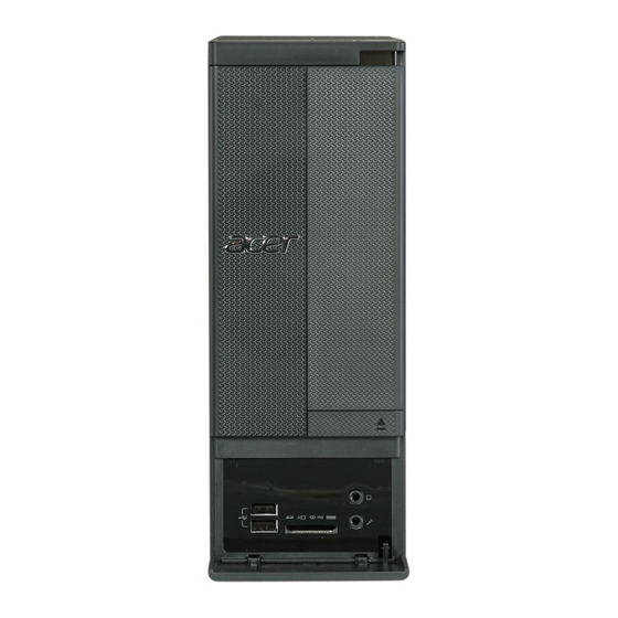
Page 12: System Tour
Multi-in-1 optional card reader supporting Memory Stick (MS), xD-Picture Card (xD), Secure Digital (SD), MultiMediaCard (MMC), Reduced-Size MultiMediaCard (RS-MMC), CompactFlash (CF) Types I and II, and Memory Stick PRO (MS PRO) USB 2.0 ports Acer logo Aspire AX1930 Service Guide... -
Page 13: Rear Panel
Rear Panel Component Expansion slots Microphone jack USB 2.0 ports USB 3.0 ports HDMI port PS/2 mouse connector PS/2 keyboard connector Voltage selector switch Power connector Kensington lock Key lock External monitor port LAN connector Line-in jack Line-out jack Aspire AX1930 Service Guide... - Page 14 Aspire AX1930 Service Guide...
-
Page 15: System Utilities
System Utilities CMOS Setup Utility CMOS setup is a hardware configuration program built into the system ROM, called the complementary metal- oxide semiconductor (CMOS) Setup Utility. Since most systems are already properly configured and optimized, there is no need to run this utility. You will need to run this utility under the following conditions. When changing the system configuration settings •... -
Page 16: Entering Cmos Setup
Entering CMOS setup Turn on the computer and the monitor. If the computer is already turned on, close all open applications, then restart the computer. During POST, press Delete. If you fail to press Delete before POST is completed, you will need to restart the computer. The Setup Main menu will be displayed showing the Setup’s menu bar. -
Page 17: Setup Utility Menus
Setup Utility Menus The Setup Main menu includes the following main setup categories. Main • Advanced • Power • Security • Boot Options • Exit • In the descriptive table following each of the menu screenshots, settings in boldface are the default and suggested settings. - Page 18 Main The Main menu displays basic information about the system. Parameter Description System BIOS Version Version number of the BIOS setup utility. Build Date Date when the BIOS setup utility was built. Processor Type of CPU installed on the system. Core Frequency Core speed of the CPU installed on the system.
- Page 19 Advanced Parameter Miscellaneous Advanced Chipset Configuration Integrated Peripherals PC Health Status Aspire AX1930 Service Guide Description Press Enter to access the Miscellaneous submenu Press Enter to access the Advanced Chipset Configuration submenu Press Enter to access the Integrated Peripherals submenu Press Enter to access the PC Health Status submenu...
- Page 20 Miscellaneous Parameter Description AHCI Port1/2/3/4/5/6 Displays the status of auto detection of the AHCI device. Clock to All DIMM/PCI/PCIE Enables or disables the system to detect the DIMM/PCI/PCIE clock automatically during bootup. Spread Spectrum Enables or disables the reduction of the mainboard’s EMI. Note: Remember to disable the Spread Spectrum feature if you are overclocking.
-
Page 21: Advanced Chipset Configuration
Advanced Chipset Configuration Parameter Description Intel EIST When enabled, this feature allows the OS to reduce power consumption. When disabled, the system operates at maximum CPU speed. Intel Turbo Boost Enables or disables Intel Turbo Boost Technology. Intel AES-NI Enables or disables Advanced Encryption Standard New Instructions (AES-NI). -
Page 22: Integrated Peripherals
Integrated Peripherals Parameter Description Onboard IDE Controller Enables or disables the onboard IDE controller. Onboard SATA Controller Enables or disables the onboard SATA controller. Onboard SATA Mode Select an operating mode for the onboard SATA. Onboard USB Controller Enables or disables support for legacy USB devices Legacy USB Support Enables or disables support for legacy USB devices. - Page 23 Parameter Description Onboard Floppy Controller Enables or disables the onboard floppy controller. Serial Port1/2 Address Specify the base I/O port address and interrupt request address of serial port 1 or 2. Serial Port2 Mode Select a mode for serial port 2. Parallel Port Address Specify the parallel port (LPT1) base address.
- Page 24 PC Health Status Parameter Description System Shutdown Set the shutdown temperature of the system. Temperature CPU Shutdown Set the shutdown temperature of the CPU. Temperature Smart Fan Enables or disables the smart system fan control function. Option 0°C Disabled 0°C Disabled Enabled Disabled...
- Page 25 Power Parameter Description ACPI Aware OS Enables or disables the Advanced Configuration and Power Management (ACPI) function. ACPI Suspend Mode Select an ACPI state. Deep Power Off Mode Enables or disables the deep power off mode. Power On by RTC Alarm Enables or disables real time clock (RTC) to generate a wake event.
- Page 26 Security Parameter Description Supervisor Password Indicates the status of the supervisor password. User Password Indicates the status of the user password. Change Supervisor Supervisor password prevents unauthorized access to the BIOS Setup Utility. Password Press Enter to change the Supervisor password. Change User Password Press Enter to change the User password.
-
Page 27: Boot Options
Boot Options Parameter Description 1st/2nd/3rd/4th/5th Boot Specifies the boot order from the available devices. Device EFI Device Priority Press Enter to access the EFI Device Priority submenu and specify the boot device priority sequence from available EFI devices. Hard Disk Drive Priority Press Enter to access the Hard Disk Drive Priority submenu and specify the boot device priority sequence from available hard drives. - Page 28 Exit Parameter Description Save & Exit Setup When you have completed the system configuration changes, select this option to leave the BIOS Setup Utility and reboot the computer, so the new system configuration parameters can take effect. Select Save & Exit Setup from the Exit menu and press Enter. Discard Changes and Exit Select this option to quit the BIOS Setup Utility without making any permanent changes to the Setup...
-
Page 29: System Disassembly
System Disassembly This chapter contains step-by-step procedures on how to disassemble the desktop computer for maintenance and troubleshooting. Disassembly Requirements To disassemble the computer, you need the following tools: Wrist grounding strap and conductive mat for preventing electrostatic discharge • Flat-blade screwdriver •... -
Page 30: Disassembly Procedures
Disassembly Procedures Removing the Side Panel Put the computer on a flat surface. Remove the two screws located on the rear edge of the side panel. Slide the side panel toward the back of the chassis until the tabs on the cover disengage with the slots on the chassis. -
Page 31: Removing The Front Bezel
Removing the Front Bezel Release the front bezel retention tabs from the chassis interior. Pull the front bezel away from the chassis. NOTE: The power switch and LED cable from the front bezel is still connected to its connector on the mainboard. -
Page 32: Removing The Heatsink Fan Assembly
Removing the Heatsink Fan Assembly WARNING: The heatsink becomes very hot when the system is on. NEVER touch the heatsink with any metal or with your hands. Disconnect the heatsink fan cable from its mainboard connector. Use a long-nosed screwdriver to loosen the four screws on the heatsink fan assembly. Aspire AX1930 Service Guide... - Page 33 Lift the heatsink fan assembly off the mainboard. Lay it down in an upright position—with the thermal patch facing upward. Do not let the thermal patch on the heatsink fan assembly touch the work surface. Use an alcohol pad to wipe off the thermal grease from both the heatsink and the processor. Aspire AX1930 Service Guide...
-
Page 34: Removing The Processor
Removing the Processor IMPORTANT:Before removing a processor from the mainboard, make sure to create a backup file of all important data. WARNING:The processor becomes very hot when the system is on. Allow it to cool off first before handling. Press the load lever (1), then move it to the right to release the load lever (2) from the retention tab. Pull the load leaver to the fully open, upright position. - Page 35 Open the load plate.. Pull out the processor from the socket. IMPORTANT:If you are going to install a new processor, note the arrow on the corner, highlighted with a circle in the photo above, to make sure the processor is properly oriented over the socket. Aspire AX1930 Service Guide...
-
Page 36: Removing The Hdd-Odd Bracket
Removing the HDD-ODD Bracket Remove the two screws that secure the HDD-ODD bracket to the chassis. Lift up the HDD-ODD bracket. Aspire AX1930 Service Guide... -
Page 37: Removing The Optical Drive And The Hard Disk Drive
Removing the Optical Drive and the Hard Disk Drive Disconnect the data and power cables from the rear of the optical drive. Disconnect the other end of the data cable from the mainboard. Aspire AX1930 Service Guide... - Page 38 Disconnect the data and power cables from the rear of the hard disk drive. Disconnect the other end of the data cable from the mainboard. Aspire AX1930 Service Guide...
- Page 39 Remove the screws that secure the optical drive to the HDD-ODD bracket. Pull the optical drive out of the drive bay. Aspire AX1930 Service Guide...
- Page 40 Remove the four screws that secure the hard disk drive to the HDD bracket. Slide the hard disk drive out of the bracket. Aspire AX1930 Service Guide...
-
Page 41: Detaching The Front Bezel
Detaching the Front Bezel Disconnect the power switch and LED cable from the mainboard. Pull out the power switch and LED cable from the chassis. Detach the front bezel. Aspire AX1930 Service Guide... -
Page 42: Removing The Expansion Boards
Removing the Expansion Boards Remove the screw from the expansion card bracket opposite the PCI_1 slot. Push to open the expansion slot lock in the direction indicated. Gently pull up the expansion board (1), move it slightly to the left and remove (2) from the slot. Note: Circuit board >10 cm2 has been highlighted with the yellow rectangle as shown above. - Page 43 Remove the screw from the expansion card bracket opposite the PCIEX2 slot. Gently pull up the TV tuner board (1), move it slightly to the left and remove (2) from the slot. Note: Circuit board >10 cm2 has been highlighted with the yellow rectangle as shown above.
-
Page 44: Removing The Memory Modules
Removing the Memory Modules Press the holding clips (1) on both sides of the DIMM slot outward to release the DIMM. Gently pull the DIMM upward (2) to remove it from the chassis. Note: Circuit board >10 cm2 has been highlighted with the yellow rectangle as shown above. -
Page 45: Removing The Power Supply
Removing the Power Supply Disconnect the 4-pin and 24-pin ATX power supply cables from the mainboard. Remove the screw that secures the power supply Remove the two screws that secure the power supply module. Aspire AX1930 Service Guide... - Page 46 Push the power supply module (1) toward the front. Tilt the power supply module slightly to the right (2) and lift it out (3) of the chassis. Aspire AX1930 Service Guide...
-
Page 47: Removing The Front I/O And Card Reader Board
Removing the Front I/O and Card Reader Board Disconnect the front I/O board and card reader board cables from their mainboard connectors. Open the plastic clip (1) and release the cables from the metal clip (2) in the direction indicated. Aspire AX1930 Service Guide... - Page 48 Remove the screw that secures the bracket to the unit. Pull the bracket with the cables out of the unit, as shown. Remove the two screws that secure the board to the bracket. Aspire AX1930 Service Guide...
- Page 49 Pull the board out of the bracket. Note: Circuit board >10 cm2 has been highlighted with the yellow rectangle as shown above. Please follow local regulations for disposal of detached circuit boards. Aspire AX1930 Service Guide...
-
Page 50: Removing The Mainboard
Removing the Mainboard Remove the six screws that secure the mainboard to the housing. Note: Circuit board >10 cm2 has been highlighted with the yellow rectangle as shown above. Please follow local regulations for disposal of detached circuit boards. Lift the board off the housing. Aspire AX1930 Service Guide... - Page 51 Remove the RTC battery. NOTE: The RTC battery has been highlighted with a yellow circle as shown above. Please follow local regulations for disposal of used RTC batteries. Aspire AX1930 Service Guide...
- Page 52 Aspire AX1930 Service Guide...
-
Page 53: Troubleshooting
System Check Procedures IMPORTANT The diagnostic tests described in this chapter are only intended to test Acer products. Non-Acer products, prototype cards, or modified options can give false errors and invalid system responses. -
Page 54: Checkpoints
Verify that all power and data cables are firmly and properly attached to the installed drives. Verify that all cable connections inside the system are firmly and properly attached to their appropriate mainboard connectors. Verify that all components are Acer-qualified and supported. 10. Reinstall the side panel. 11. Power on the system. -
Page 55: Boot Block Recovery Code Checkpoints
Checkpoint Description Bootblock code is copied from ROM to lower system memory and control is given to it. BIOS now executes out of RAM. Both key sequence and OEM specific method is checked to determine if BIOS recovery is forced. Main BIOS checksum is tested. If BIOS recovery is necessary, control flows to checkpoint E0. -
Page 56: Post Code Checkpoints
POST Code Checkpoints The POST code checkpoints are the largest set of checkpoints during the BIOS preboot process. The following table describes the type of checkpoints that may occur during the POST portion of the BIOS. Checkpoint Description Disable NMI, Parity, video for EGA, and DMA controllers. Initialize BIOS, POST, Runtime data area. - Page 57 Checkpoint Description Mid POST initialization of chipset registers. Detect different devices (Parallel ports, serial ports, and coprocessor in CPU, ... etc.) successfully installed in the system and update the BDA, EBDA…etc. Programming the memory hole or any kind of implementation that needs an adjustment in system RAM size if needed.
-
Page 58: Post Error Indicators
DIM Code Checkpoints The Device Initialization Manager (DIM) gets control at various times during BIOS POST to initialize different system busses. The following table describes the main checkpoints where the DIM module is accessed. Checkpoint Description Initialize different buses and perform the following functions: Reset, Detect, and Disable (function 0);... - Page 59 Memory Message Description Gate20 Error The BIOS is unable to properly control the mainboard’s Gate A20 function, which controls access of memory over 1 MB. This may indicate a problem with the mainboard. Multi-Bit ECC Error This message will only occur on systems using ECC enabled memory modules. ECC memory has the ability to correct single-bit errors that may occur from faulty memory modules.
-
Page 60: Storage Device
Storage Device Message Description Primary Master Hard The IDE/ATAPI device configured as Primary Master could not be properly Disk Error initialized by the BIOS. This message is typically displayed when the BIOS is trying to detect and configure IDE/ATAPI devices in POST. Primary Slave Hard The IDE/ATAPI device configured as Primary Slave could not be properly initialized Disk Error... - Page 61 Message Description 3rd Slave Drive - The IDE/ATAPI device configured as Slave in the 3rd IDE controller failed an ATAPI ATAPI Incompatible compatibility test. This message is typically displayed when the BIOS is trying to detect and configure IDE/ATAPI devices in POST. 4th Master Drive - The IDE/ATAPI device configured as Master in the 4th IDE controller failed an ATAPI Incompatible...
-
Page 62: System Configuration
Virus-related Message Description BootSector Write!! The BIOS has detected software attempting to write to a drive’s boot sector. This is flagged as possible virus activity. This message will only be displayed if Virus Detection is enabled in AMIBIOS setup. VIRUS: Continue If the BIOS detects possible virus activity, it will prompt the user. - Page 63 CMOS Message Displayed Description CMOS Date/Time Not The CMOS date and/or time are invalid. This error can be resolved by readjusting the system time in AMIBIOS Setup. CMOS Battery Low CMOS battery is low. This message usually indicates that the CMOS battery needs to be replaced.
- Page 64 Index of Symptom-to-FRU Error Messages To use the information in this section to diagnose a problem: Find the error symptom in the left column. If directed to a check procedure, replace the FRU indicated in the check procedure. If no check procedure is indicated, the first Action/FRU item listed in the right column is the most likely cause.
- Page 65 Hard Disk Drive-related Symptoms Symptom/Error Hard disk drive test failed. Hard disk drive cannot format completely. Hard disk drive has write error. Hard disk drive LED fails to light, but system operates normally. NOTE Make sure the hard disk drive is configured correctly in CMOS Setup and that cable/jumper are set correctly before diagnosing any hard disk drive problems.
- Page 66 Real-Time Clock-related Symptoms Symptom/Error Real-time clock is inaccurate. Audio-related Symptoms Symptom/Error Audio software program invoked but no sound comes from speakers. Modem-related Symptoms Symptom/Error Modem ring cannot wake up system from suspend mode. Data/fax modem software program invoked but cannot receive/send data/fax Fax/voice modem software program invoked but has no sound output.
- Page 67 Printer-related Symptoms Symptom/Error Printing failed. Printer problems. Keyboard-related Symptoms Symptom/Error Some or all keys on keyboard do not work. Power Supply-related Symptoms Symptom/Error Pressing the power button does not turn off the system. (Only unplugging the power cord from electrical outlet can turn off the system.) Pressing the power button does not turn on the system...
-
Page 68: Beep Codes
Follow the procedures below to isolate the failing FRU. Do not isolate non-defective FRU. Power off the computer. Visually check them for damage. If any problems are found, replace the FRU. Remove or disconnect all of the following devices: • Non-Acer devices • Printer, mouse, and other external devices • Hard disk drive •... -
Page 69: Configuring The Me Firmware
Configuring the ME Firmware You need to disable the Manageability Engine (ME) firmware before updating the BIOS. Use the ME_DISABLE jumper to do this. • 1-2 position: Normal operation (default) • 2-3 position: ME disable To disable the ME firmware: Turn off the power to the computer and all peripherals. -
Page 70: Clearing Cmos
Clearing CMOS You may need to clear the Setup configuration values (CMOS) if the configuration has been corrupted, or if incorrect settings made in the Setup Utility caused error messages to be unreadable. This procedure will clear the BIOS supervisor password as well. Use the CLR_CMOS jumper to clear the CMOS data. -
Page 71: Bios Recovery
BIOS Recovery When you boot up the computer and you hear one long beep, followed by a shorter one, the system BIOS is damaged. This maybe cause by an interruption during a BIOS flash procedure (e.g. a power outage) or a corrupted BIOS code, which will cause the system to go into an unbootable state.You need to access and execute the boot block program to reboot the computer and recover the regular BIOS code. -
Page 72: Bios Update
BIOS Update Updating the BIOS in DOS Mode Press the power button to turn on the computer and boot to DOS mode. Key in 'cd dostool'. (Go to BIOS path like "A:\DOSTOOL") Key in 'flash2M.bat' or 'flash2M'. Press Enter to flash the system BIOS. Reboot the computer. -
Page 73: Updating The Bios In Windows Mode
Updating the BIOS in Windows Mode This BIOS updating procedure is for a computer running a 32- or 64-bit Windows OS. Press the power button to turn on the computer. Click Start | Command Prompt | Run as administrator. Perform the steps below if your computer is running 32-bit Windows. Key in 'cd wintool\32'. - Page 74 Press Enter to flash the system BIOS. Perform the steps below if your computer is running 64-bit Windows. Key in 'cd wintool\64'. (Go to BIOS path like "D:\WinTool\64") Key in 'flash2M.bat' or 'flash2M'. Press Enter to flash the system BIOS. Aspire AX1930 Service Guide...
- Page 75 Reboot the computer. Press Delete to run the CMOS Setup Utility. Press F9 to load the system default settings. Select Ok, then press Enter. Press F9 to save the default settings and close the Setup utility. 10. Select Ok, then press Enter. Aspire AX1930 Service Guide...
- Page 76 Aspire AX1930 Service Guide...
-
Page 77: System Architecture
System Architecture This chapter shows the system block diagram and board layout. Block Diagram The core subsystems of the computer are depicted in the following block diagram. AX1930 Service Guide Chapter 5... -
Page 78: Mainboard Layout
Mainboard Layout This section shows the major mainboard components. Label Description ATX_12V ATX 4-pin connector Processor socket SYS_FAN System fan connector CPU_FAN CPU cooling fan connector DIMM1-2 DDR3 240-pin slots GPIO1 General Purpose I/O Signal 1 GPIO2 General Purpose I/O Signal 2 ATX_POWE Standard 24-pin power connector... -
Page 79: Jumper Setting
Jumper Setting This section explains how to set the jumper for correct configuration of the main board. Jumpers with more than one pin are numbered. When setting a jumper, ensure that the jumper caps are placed on the correct pins. The following illustration shows the location of the jumpers. - Page 80 AX1930 Service Guide...
-
Page 81: Field Replaceable Unit (Fru) List
Service Guide. For Acer authorized service providers, your Acer office may have a different part number code from those given in the FRU list of this printed Service Guide. You MUST use the local FRU list provided by your regional Acer office to order FRU parts for service. -
Page 82: Exploded Diagram
Exploded Diagram Description Lowercase assembly HDD-ODD bracket Front I/O and card reader board bracket Front cover assembly Lowercase support Side cover Front I/O and card reader board Plastic cable clip Screw I #6-32 L5 Screw Pan, M3 L5 Screw Flat #6-32*3/16 NI Screw Pan #6-32 L6 NI Quantity Aspire AX1930 Service Guide... -
Page 83: Ax1930 Fru List
HDMI W/LP BRACKET ROHS BOARDS VGA CARD PCPARTNER 288- 2E142-C01AC HD5570 1GB 128BITS SDDR3 DVI+HDMI LP (NEW HYNIX -1.2) Aspire AX1930 Service Guide Description Acer Part No. PHILIPS VISTA MCE RV.11000.007 RECEIVER REMOTE CTRL PHILIPS RT.11300.021 RC2604307/ F-IO BD USB 2.0 2 USB 55.NCM01.001... - Page 84 405 1GB 64BITS DDR3 DVI + DP HYNIX LP VGA CARD 288-5N158-A20AC NV 405 1GB 64BITS DDR3 DVI + DP SAMSUNG LP Description Acer Part No. PCP NV GT315 1GB SDI VG.PCPT3.181 DP/DVI/DSUB ATX PCP NV GT315 1GB HYNIX VG.PCPT3.182...
- Page 85 1830MM BLACK THAILAND POWER CORD 250V 3PIN 1800MM UK HDD SATA CABLE HDD SATA CABLE Aspire AX1930 Service Guide Description Acer Part No. IC VGA GT435M 2GB VG.PCPT4.354 SDDR3 DVI/HDMI/LP SDI IC VGA GT435M 2GB VG.PCPT4.352 SDDR3 HYNIX DVI/HDMI PCP NV GT530 2GB DDR3 VG.PCPT5.302...
- Page 86 ASSEMBLY FRONT BEZEL W/ LED SWITCH CABLE FOR CARD READER ASSEMBLY FRONT BEZEL W/ LED SWITCH CABLE FOR NONE CARD READER Description Acer Part No. C.A. SATA ODD GTL ELENA 50.SFF01.003 C.A. SATA ODD VSO 50.SFF01.004 ELENA TELEPHONE CABLE 50.GB001.001 DVI TO VGA DONGLE D0.VGA26.P01...
- Page 87 (HF+WIN7) SATA ODD PLDS DVD-ROM HH DL 16X DH-16D5SH LF+HF BLACK BEZEL SATA W/WIN7 Aspire AX1930 Service Guide Description Acer Part No. IC CPU SANDY BRIDGE I3- KC.21001.CI3 2100 3MB 2C 3.1GH IC CPU SANDY BRIDGE I3- KC.21201.CI3 2120 3MB 2C 3.3GH IC CPU SANDY BRIDGE I5- KC.23001.CI5...
- Page 88 SATA II 16MB LF F/W:CC44 HDD 500GB 3.5" 7200RPM SATA II 16MB HGST HDS721050CLA362 JUPITER HDD 3.5" 500GB 7200RPM SATA WD XL320M WD5000AAKS- 22M9A0 Description Acer Part No. HDD 1TB WD10EADS- KH.01K08.005 22M2B0 GP HDD 1TB 3.5" WD KH.01K08.008 WD10EARS-22Y5B1 GP 5.4K HDD 1TB 3.5"...
- Page 89 KB.RF40B.048 + MS.11200.073 KEYBOARD KIT 105KEY RF2.4 LITE-ON SK-9660B BLACK PORTUGUESE WITH MOUSE W/ KB.RF40B.049 + MS.11200.073 Aspire AX1930 Service Guide Description Acer Part No. HDD 500GB 3.5" SGT KH.50001.022 ST3500413AS 6G 7.2K HDD 500GB 3.5" WD KH.50008.022 WD5000AAKX-221CA0 7.2K HDD 640GB HGST KH.64007.002...
- Page 90 ICELANDIC WITH MOUSE W/ KB.RF40B.061 + MS.11200.073 KEYBOARD KIT 105KEY RF2.4 LITE-ON SK-9660B BLACK NORWEGIAN WITH MOUSE W/ KB.RF40B.062 + MS.11200.073 Description Acer Part No. KB&MS PACK RF LITEON KB.RF40B.050 A1B CA-FR KB&MS PACK RF LITEON KB.RF40B.051 A1B XC KB&MS PACK RF LITEON KB.RF40B.052...
- Page 91 W/KB.RF40B.075 + MS.11200.073 KEYBOARD KIT 104KEY RF2.4 LITE-ON SK-9660B BLACK KAZAKH WITH MOUSE W/ KB.RF40B.076 + MS.11200.073 Aspire AX1930 Service Guide Description Acer Part No. KB&MS PACK RF LITEON KB.RF40B.063 A1B HE KB&MS PACK RF LITEON KB.RF40B.064 A1B PL KB&MS PACK RF LITEON KB.RF40B.065...
- Page 92 ON SK-9621B BLACK SPANISH KEYBOARD 105KEY USB LITE- ON SK-9621B BLACK PORTUGUESE KEYBOARD 105KEY USB LITE- ON SK-9621B BLACK CANADIAN FRENCH Description Acer Part No. KB&MS PACK RF LITEON KB.RF40B.077 A1B TURKMEM KB&MS PACK RF LITEON KB.RF40B.078 A1B NOR KB&MS PACK RF LITEON KB.RF40B.079...
- Page 93 ON SK-9621B BLACK ROMANIAN KEYBOARD 105KEY USB LITE- ON SK-9621B BLACK TURKISH KEYBOARD 105KEY USB LITE- ON SK-9621B BLACK TURKISH-Q Aspire AX1930 Service Guide Description Acer Part No. KB SK-9621B USB 107KS KB.USB0B.339 BLACK BRAZILIAN PO KB SK-9621B USB 109K KB.USB0B.340 BLACK JAPANESE KB SK-9621B USB 105K KB.USB0B.341...
- Page 94 PRIMAX KB36211 BLACK JAPANESE KEYBOARD 105KEY USB PRIMAX KB36211 BLACK GERMAN KEYBOARD 105KEY USB PRIMAX KB36211 BLACK ITALIAN Description Acer Part No. KB SK-9621B USB 105K KB.USB0B.363 BLACK ARABIC/FRENCH KB SK-9621B USB 104K KB.USB0B.364 BLACK KAZAKH KB SK-9621B USB 104K KB.USB0B.365...
- Page 95 KEYBOARD 105KEY USB PRIMAX KB36211 BLACK ROMANIAN KEYBOARD 105KEY USB PRIMAX KB36211 BLACK TURKISH Aspire AX1930 Service Guide Description Acer Part No. KB PRIMAX KB36211 USB KB.USB0P.014 105KS BLACK FRENCH KB PRIMAX KB36211 USB KB.USB0P.015 105KS BLACK SWEDIS KB PRIMAX KB36211 USB KB.USB0P.016...
- Page 96 KEYBOARD 105KEY PS/2 LITE- ON SK-9611 BLACK CANADIAN FRENCH KEYBOARD 107KEY PS/2 LITE- ON SK-9611 BLACK BRAZILIAN PORTUGUESE Description Acer Part No. KB PRIMAX KB36211 USB KB.USB0P.033 105KS BLACK TURKIS KB PRIMAX KB36211 USB KB.USB0P.034 105KS BLACK ARABIC KB PRIMAX KB36211 USB KB.USB0P.035...
- Page 97 ON SK-9611 BLACK CZECH KEYBOARD 105KEY PS/2 LITE- ON SK-9611 BLACK ROMANIAN KEYBOARD 105KEY PS/2 LITE- ON SK-9611 BLACK TURKISH Aspire AX1930 Service Guide Description Acer Part No. KB SK-9611 ?PS/2 ?109K KB.PS20B.125 ?BLACK JAPANESE KB SK-9611 ?PS/2 ?105K? KB.PS20B.126 BLACK GERMAN KB KB36211 PS2 105K KB.PS20P.084...
- Page 98 PORTUGUESE KEYBOARD 105KEY PS/2 PRIMAX KB36111 BLACK CANADIAN FRENCH KEYBOARD 107KEY PS/2 PRIMAX KB36111 BLACK BRAZILIAN PORTUGUESE Description Acer Part No. KB SK-9611 ?PS/2 ?105K? KB.PS20B.147 BLACK TURKISH-Q KB SK-9611 ?PS/2 ?105K? KB.PS20B.148 BLACK ARABIC/FRE KB SK-9611 ?PS/2 ?104K? KB.PS20B.149...
- Page 99 KEYBOARD 104KEY PS/2 PRIMAX KB36111 BLACK CZECH KEYBOARD 105KEY PS/2 PRIMAX KB36111 BLACK ROMANIAN Aspire AX1930 Service Guide Description Acer Part No. KB KB36211 PS2 109K KB.PS20P.083 BLACK JAPANESE KB KB36211 PS2 105K KB.PS20P.085 BLACK ITALIAN KB KB36211 PS2 105K KB.PS20P.087...
- Page 100 MEMORY DDR3 1333MHZ 1G UNBUFFERED DIMM W/O ECC F DIE (46NM) MEMORY A-DATA UNB-DIMM DDRIII 1333 1GB AD63I1A0823EU LF 128*8 0.065UM Description Acer Part No. KB KB36211 PS2 105K KB.PS20P.104 BLACK TURKISH KB KB36211 PS2 105K KB.PS20P.105 BLACK TURKISH-Q KB KB36211 PS2 105K KB.PS20P.106...
- Page 101 MOUSE LOGITECH OPTICAL MOUSE PS2 M-S0004-O MOUSE USB LITEON SM9020B OPTICAL NI BLACK MOUSE USB A1B PRIMAX MOF9UO BLACK COLOR Aspire AX1930 Service Guide Description Acer Part No. DIMM 1G GU502203EP0201 KN.1GB0H.015 UNB. DIMM 2G KN.2GB03.022 NT2GC64B88B0NF-CG DDR3 UNB. DIMM 2G KN.2GB07.002...
- Page 102 SCREW FLAT #6-32*3/16 NI SCREW MA HEX #6-32 5MM NI SCREW #6-32 L5 PAN NI SPEAKER SPEAKER CHIAMAW 9M-20A200- 000 ACER LOGO LF 0810 SPEAKER ASI USB 2.0 Q4-08 SPEAKER NEOSONICA USB NEO 2003 WITH BLACK COLOR Description Acer Part No.
- Page 103 Aspire AX1930 Service Guide...
-
Page 104: Technical Specifications
Technical Specifications This section provides technical specifications for the system. Processor Item Type Intel Core processor family Processor Number i7-2600 Number of Cores Quad Clock Speed (GHz) Turbo Speed (GHz) Cache Size (MB) Voltage (V) Socket LGA 1155 Thermal Design Power (W) System Board Major Chips Item... - Page 105 System Memory Item DIMM Sockets Four Memory Type DDR3-1066/1333 unbuffered DIMM Module Name PC3-8500/10600 Organization Maximum 8 GB Memory Vendor Samsung DIMM Size (GB) 1, 2, 4 System BIOS Item BIOS Vendor American Megatrends Inc. BIOS Version P01-A0 PCI Interface Item Number of Slots PCI Express x 1 slot...
- Page 106 VGA Interface Item Connector Network Interface Item LAN Controller Supports LAN Protocol LAN Connector Type SATA Interface Item SATA Controller Connectors Audio Interface Item Audio Controller Connectors Keyboard and Input Devices Item Controller Connectors Aspire AX1930 Service Guide Specification VGA/monitor port Specification Intel 82579V Gbe LAN controller PHY 10/100/1000 Mbps...
-
Page 107: Optical Drive
Optical Drive BD Combo Module Item Vendor Model name Drive type Write Speed Read Speed Data Transfer Rate Access Time Buffer Size Interface Type Specification HLDS CH20N BD-Combo DVD-R 2x, 4x CLV, 8x ZCLV, 8x PCAV, 12x PCAV, 16x CAV DVD-R DL 2x, 4x CLV DVD-RW2x, 4x, 6x CLV DVD-RAM2x, 3x CLV, 5x PCAV... - Page 108 Super Multi Item Vendor Model Name Drive Type Write Speed Read Speed Data Transfer Rate Access Time Buffer Size Interface Type Aspire AX1930 Service Guide Specification HLDS GH60N Super Multi CD-R: 4x, 8x, 16x CLV, 24x, 32x, 40x PCAV CD-RW: 4x, 10x,16x CLV, 24x, 32x ZCLV (High Speed: 10x, Ultra Speed: 16x, 24x, US Plus: 16x, 24x, 32x) DVD+R:2.4x, 4x, 6x CLV, 8x,12x ZCLV, 8x, 12x...
- Page 109 DVD-ROM Item Vendor Model Name Drive Type Write Speed Read Speed Data Transfer Rate Access Time Buffer Size Interface Type Specification HLDS DH40N DVD-ROM — — — — — Serial ATA PLDS DH-16D5SH DVD-ROM — DVD-ROM (single layer) 2x CLV, 4X, 6X, 8X, 10X, 12X, 16X CAV DVD-ROM (dual layer) 2x CLV, 4X, 6X, 8X CAV...
- Page 110 Aspire AX1930 Service Guide...
- Page 111 ACPI, see Advanced Configuration Power Interface 2 Advanced Configuration Power Interface specifications 2 antivirus software 2 audio headphone jack 4 microphone jack, rear 5 troubleshooting 58 Basic Input/Output System, see BIOS 7 beep codes 60 BIOS 97 checkpoints 46 clear CMOS 62 CMOS RAM 7 configure 8 crisis recovery disk 63...
- Page 112 hardware exploded view 74 FRU list 73 troubleshooting 45 HDD, see hard disk drive 1 HDD-ODD bracket remove 28 headphone jack 4 humidity 3 I/O ports 2 jack line-in 5 line-out 5 microphone-in 4 lock Kensington 5 Key 5 main board placement 70 main unit disassembly audio board 39 heat sink 24...
- Page 113 system views front view 4 system weight 3 technical specifications 96 temperature operating 3 troubleshooting BIOS checkpoints 46 BIOS recovery 63 BIOS update 64 clearing CMOS 62 component failure 56 disabling ME firmware 61 hardware diagnostic procedure 45 POST error indicators 50 undetermined problems 60 USB ports front 2, 4, 5...