Table of Contents
Advertisement
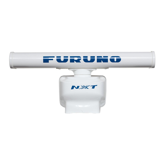
Installation Manual
RADAR SENSOR
DRS6A-NXT/DRS12A-NXT
MODEL
DRS25A-NXT
(Product Name: SOLID STATE DOPPLER RADAR)
SAFETY INSTRUCTIONS ................................................................................................ i
SYSTEM CONFIGURATION .......................................................................................... iii
INSTALLATION SPECIFICATIONS............................................................................... iv
FOREWORD .................................................................................................................... v
EQUIPMENT LISTS........................................................................................................ vi
1. INSTALLATION AND WIRING................................................................................... 1
1.1 Mounting Considerations ......................................................................................................1
1.2 Included Items.......................................................................................................................4
1.3 Required Tools and Materials ...............................................................................................5
1.4 Fastening the Radiator to the Radiator Bracket....................................................................6
1.5 Mounting the Antenna Unit ...................................................................................................8
1.6 Wiring..................................................................................................................................11
2. INITIAL SETUP......................................................................................................... 15
2.1 Initial Setup for TZT9/TZT14/TZTBB ..................................................................................16
2.2 Initial Setup for TZTL12F/TZTL15F/TZT2BB/TZT12F/TZT16F/TZT19F.............................18
3. MAINTENANCE, TROUBLE SHOOTING ................................................................ 21
3.1 Maintenance .......................................................................................................................22
3.2 Troubleshooting ..................................................................................................................23
3.3 Replacement of Fuse..........................................................................................................23
3.4 Life of Parts.........................................................................................................................24
APPENDIX 1 RADIO REGULATORY INFORMATION ............................................AP-1
SPECIFICATIONS ..................................................................................................... SP-1
PACKING LISTS ......................................................................................................... A-1
OUTLINE DRAWINGS ................................................................................................ D-1
INTERCONNECTION DIAGRAM ................................................................................ S-1
www.furuno.com
All brand and product names are trademarks, registered trademarks or service marks of their respective holders.
Advertisement
Table of Contents
Troubleshooting

Related Manuals for Furuno DRS12A-NXT


Summary of Contents for Furuno DRS12A-NXT
-
Page 1: Table Of Contents
Installation Manual RADAR SENSOR DRS6A-NXT/DRS12A-NXT MODEL DRS25A-NXT (Product Name: SOLID STATE DOPPLER RADAR) SAFETY INSTRUCTIONS ....................i SYSTEM CONFIGURATION ..................iii INSTALLATION SPECIFICATIONS................iv FOREWORD ........................v EQUIPMENT LISTS......................vi 1. INSTALLATION AND WIRING................... 1 1.1 Mounting Considerations ......................1 1.2 Included Items........................4 1.3 Required Tools and Materials ....................5... -
Page 2: Safety Instructions
SAFETY INSTRUCTIONS The installer of the equipment must read the safety instructions before attempting to install the equipment. Indicates a potentially hazardous situation which, WARNING if not avoided, can result in death or serious injury. Indicates a potentially hazardous situation which, CAUTION if not avoided, can result in minor or moderate injury. - Page 3 - Name: FURUNO (UK) LTD. - Address: West Building Penner Road Havant Hampshire PO9 1QY, U.K. Program No. • 0359423-01.** ** denotes minor modifications. CE declarations With regard to CE declarations, please refer to our website (www.furuno.com), for further information about RoHS conformity declarations.
-
Page 4: System Configuration
NavNet TZtouch/NavNet TZtouch2/ NavNet TZtouch3 NavNet TZtouch3 This radar series is compatible with the FURUNO Multi Function Displays and software version combinations shown below. The combination with other models or software versions may not op- erate properly. • TZT9, TZT14 and TZTBB: Version 6.01 or later TZTL12F, TZTL15F and TZT2BB: Version 6.21 or later... -
Page 5: Installation Specifications
Note 1: Radiator XN10A is only used with DRS6A-NXT. Note 2: 12VDC is only used with DRS6A-NXT. DRS12A-NXT and DRS25A-NXT are 24VDC only. Note 3: DO NOT USE 15 A fuse for 24 VDC. Use of a wrong fuse can damage the equipment or cause fire. -
Page 6: Foreword
Marine Radar Congratulations on your choice of the FURUNO DRS6A-NXT/DRS12A-NXT/DRS25A-NXT Ma- rine Radar. We are confident you will see why the FURUNO name has become synonymous with quality and reliability. Since 1948, FURUNO Electric Company has enjoyed an enviable reputation for innovative and dependable marine electronics equipment. -
Page 7: Equipment Lists
EQUIPMENT LISTS Standard supply Note: Radiator XN10A is only used with DRS6A-NXT. Name Type Code No. Remarks Scanner Unit RSB-137-119 For DRS6A-NXT RSB-137-125 For DRS12A-NXT RSB-137-126 For DRS25A-NXT Radiator XN10A 3.4 ft XN12A 4 ft XN13A 6 ft Installation CP03-37101... -
Page 8: Installation And Wiring
INSTALLATION AND WIRING NOTICE Do not apply paint, anti-corrosive sealant or contact spray to coating or plastic parts of the equipment. Those items contain organic solvents that can damage coating and plastic parts, especially plastic connectors. Mounting Considerations Select a mounting location, keeping in mind the following points: •... - Page 9 Not recommended • Setup the antenna unit position on the FURUNO Multi Function Display after install- ing the unit, referring to chapter 2. If the antenna unit position is not setup correctly, the radar echoes on the display may not be aligned with the actual target’s bearing.
- Page 10 Consideration for selecting a location for installation (multiple radars) • In case multiple radars are installed on a ship, DO NOT install the DRS6A-NXT/ DRS12A-NXT/DRS25A-NXT within the range of the beam area emitted from other radar(s). Use the illustration below for reference when selecting a suitable location for installation.
-
Page 11: Included Items
1. INSTALLATION AND WIRING Included Items Radiator • Flat washer (M8, 4 pcs) • Spring washer (M8, 4 pcs) • Radiator* (1 pc): 3.4 ft, 4 ft or 6 ft • Hex. bolt (M8×30, 4 pcs) • O-ring (1 pc) •... -
Page 12: Required Tools And Materials
1. INSTALLATION AND WIRING Required Tools and Materials The following tools should be prepared in advance for this installation. Name Remarks Electrical drill For making the mounting holes, drill bit: 15 mm Phillips-head screw driver #3, for securing the cable cover Wrench For M8 (Hex. -
Page 13: Fastening The Radiator To The Radiator Bracket
1. INSTALLATION AND WIRING Fastening the Radiator to the Radiator Bracket 1. Remove the radiator cap from the radiator bracket. Radiator bracket Radiator cap 2. Apply adhesive to the surface of the radiator bracket as shown in the figure below. Top view: Scanner unit Adhesive 10 mm... - Page 14 1. INSTALLATION AND WIRING 4. Apply adhesive to the thread holes on the bottom of the radiator (4 locations). Adhesive Bottom view: Radiator 5. Prepare four bolt assemblies; pass the spring washer (M8) and flat washer (M8) through the each hex bolt (M8 30) then apply adhesive. Flat washer Adhesive Spring washer...
-
Page 15: Mounting The Antenna Unit
1. INSTALLATION AND WIRING Mounting the Antenna Unit The antenna unit can be mounted using the fixing holes (200 200 mm) of the anten- na unit. 1. Set the supplied mounting template to the mounting location, then drill four fixing holes in the mounting location. - Page 16 1. INSTALLATION AND WIRING Detailed view Vent hole: Do NOT cover this hole. Adhesive Adhesive Stud bolt Stud bolt NOTICE Do not fasten stud bolts tightly after the bolts contact with the bottom of the threaded holes. If the bolts are fastened excessively, the chassis bottom may be damaged which can result in malfunction.
- Page 17 1. INSTALLATION AND WIRING • When you hoist the antenna unit, set two belt slings to the radiator bracket. Do not set the belt slings to the radiator, the radiator may get damaged. Belt sling (2 pcs) OK: Belt slings are set to the radiator bracket. WRONG: Belt slings are set to the radiator.
-
Page 18: Wiring
• When you replace the DRS4A/6A/12A/25A with the DRS6A-NXT/DRS12A-NXT/ DRS25A-NXT, the existing cable cannot be used. Use only the cable assembly sup- plied with this radar sensor. - Page 19 1. INSTALLATION AND WIRING 1. Unfasten two screws, circled in the following figure, to remove the cable cover. Cable cover Cable cover 2. Connect the cable assembly (supplied) to the power/LAN cable that is pre-at- tached to the antenna unit. 3.
- Page 20 Cable cover - bottom view 8. Reattach the cable cover. 9. Connect the LAN connector of the cable assembly to a LAN port on the FURUNO Multi Function Display or Ethernet HUB. Note 1: Do not connect the LAN connector to on-board LAN.
- Page 21 Ethernet HUB Cable assembly LAN connector FURUNO Multi Function Display Note 2: When LAN cable extension is needed, use the optional LAN cable (MOD- Z072) and joint box (TL-CAT-012). After connection is completed, wrap the con- nector with vinyl tape to waterproof the LAN connector.
-
Page 22: Initial Setup
TZTL12F and TZTL15F and TZT2BB: Version 6.21 or later TZT12F, TZT16F and TZT19F: Version 1.05 or later Turn on the antenna unit and FURUNO Multi Function Display. Initial setup for this an- tenna must be done on the FURUNO Multi Function Display. -
Page 23: Initial Setup For Tzt9/Tzt14/Tztbb
2. INITIAL SETUP Initial Setup for TZT9/TZT14/TZTBB 1. Press the Home key (or tap the Home icon). 2. Select [Menu] on the menu icon bar to open the main menu. 3. Select [Radar]. 4. Select [Radar Source] on the [Menu Radar] sub menus, then select the radar type connected. - Page 24 2. INITIAL SETUP Menu item Description [Antenna Length] Selects the length of the antenna. RezBoost function re- flects the selection of this menu item. [Antenna Longitudinal Po- Referring to the figure on the right, enter the ra- sition] dar antenna positioning bow-stern (Longitudi- nal) and port-starboard (Lateral) position from [Antenna Lateral Position Origin...
-
Page 25: Initial Setup For Tztl12F/Tztl15F/Tzt2Bb/Tzt12F/Tzt16F/Tzt19F
2. INITIAL SETUP 1. Select a range between 0.125 and 0.25 NM and set the mode to “head up“. You can select a range by a pinch action. The range and range ring interval ap- pear at the bottom left of the screen. Range Range ring interval Zoom in... - Page 26 2. INITIAL SETUP 5. Referring to the tables below, set up the radar. [Radar] menu - [Radar Initial Setup] Menu item Description [Antenna Rotation] Select the antenna rotation speed. [Antenna Heading Align] See "How to align the antenna heading" on page 19. [Main Bang Suppression] If main bang appears at the screen center, slide the circle icon so that the main bang disappears, while watching the...
- Page 27 2. INITIAL SETUP Correct bearing of target Displayed position of target (relative to heading) Target Target Displayed Correct position bearing of of target target (relative to heading) Antenna oriented Picture appears with Antenna oriented Picture appears with to port clockwise deviation. to starboard counterclockwise deviation.
-
Page 28: Maintenance, Trouble Shooting
MAINTENANCE, TROUBLE SHOOTING Periodic checks and maintenance are important for proper operation of any electronic system. This chapter contains maintenance and troubleshooting instructions to be fol- lowed to obtain optimum performance and the longest possible life of the equipment. Before attempting any maintenance or troubleshooting procedure, please review the safety information below and at the front of this manual. -
Page 29: Maintenance
3. MAINTENANCE, TROUBLE SHOOTING Maintenance Regular maintenance is important for good performance. Check the points mentioned below every 3 to 6 months to keep the antenna unit in good working order. Check Action Remedy, remarks point Check points every 3 to 6 months Cable Check that all cables are firmly •... -
Page 30: Troubleshooting
3. MAINTENANCE, TROUBLE SHOOTING Troubleshooting The table below provides simple troubleshooting procedures to restore normal opera- tion. If you cannot restore normal operation, contact your dealer for advice. Problem Remedy The multi function display can- • Check that all cables are tightly fastened. not control the radar. -
Page 31: Life Of Parts
3. MAINTENANCE, TROUBLE SHOOTING Life of Parts Antenna Motor When an antenna motor reaches the end of its life, the antenna’s rotation may stop or abnormal noise sounds from the antenna unit. If such symptom occurs, contact your dealer about replacement of the antenna motor. Name Type Code No. -
Page 32: Appendix 1 Radio Regulatory Information
êolé et respecte les règles d'exposition aux fréquences radioélectriques (RF) CNR-102 de l'IC. Cet équipement doit etre installé et utilise en gardant une distance de 70 cm (DRS6A -NXT (RTR-119)), 190 cm (DRS12A-NXT (RTR-125)), 280 cm (DRS25-NXT (RTR-126)) ou plus entre le dispositif rayonnant et le corps. -
Page 33: Specifications
3 channel, auto/manual selectable Ch.1 (P0N/Q0N) 9380/9400 MHz Ch.2 (P0N/Q0N) 9400/9420 MHz Ch.3 (P0N/Q0N) 9420/9440 MHz Output power DRS6A-NXT 25 W DRS12A-NXT 100 W DRS25A-NXT 200 W Duplexer Ferrite circulator with diode limiter Intermediate frequency 83.75/103.75 MHz (P0N/Q0N) Range scale 0.0625/0.125/0.25/0.5/0.75/1/1.5/2/3/4/6/8/12/16/24/32/36/48/64/ 72/96* *: DRS12A/25A-NXT only P0N: 0.04 to 1.2 s, Q0N: 5 to 48 s... - Page 34 FURUNO DRS6A/12A/25A-NXT POWER SUPPLY DRS6A-NXT 12/24 VDC (10.8-15.6/21.6-31.2V): 9.5/5.0 A max. DRS12A-NXT 24 VDC (21.6-31.2V): 5.0 A max. DRS25A-NXT 24 VDC (21.6-31.2V): 5.6 A max. ENVIRONMENTAL CONDITIONS Ambient temperature -25°C to +55°C (storage: -30°C to +70°C) Relative humidity 95% or less at +40°C...
-
Page 35: Packing Lists
A C K I N G L I S T 03HZ-X-9851 -3 RSB-137-119-E, RSB-137-119-J-12A/13A N A M E DESCRIPTION/CODE № O U T L I N E Q'TY ユニット UNIT 空中線本体部 RSB-137-119-* SCANNER UNIT 000-038-054-00 予備品 SPARE PARTS 予備品 SP03-19501 SPARE PARTS 001-513-950-00 工事材料... - Page 36 A C K I N G L I S T 03IG-X-9851 -2 RSB-137-125-E, RSB-137-125-J-12A/13A N A M E DESCRIPTION/CODE № O U T L I N E Q'TY ユニット UNIT 空中線本体部 RSB-137-125-* SCANNER UNIT 000-038-058-00 予備品 SPARE PARTS 予備品 SP03-19601 SPARE PARTS 001-514-020-00 工事材料...
- Page 37 A C K I N G L I S T 03IG-X-9852 -2 RSB-137-126-E, RSB-137-126-J-12A/13A N A M E DESCRIPTION/CODE № O U T L I N E Q'TY ユニット UNIT 空中線本体部 RSB-137-126-* SCANNER UNIT 000-038-062-00 予備品 SPARE PARTS 予備品 SP03-19601 SPARE PARTS 001-514-020-00 工事材料...
- Page 41 Цялостният текст на EC/UK декларацията за съответствие може да се намери на следния интернет адрес: Spanish Por la presente, Furuno Electric Co., Ltd. declara que el tipo de equipo radioeléctrico arriba mencionado es conforme con la Directiva 2014/53/UE, SI 2017/1206. (ES) El texto completo de la declaración de conformidad de la EU/UK está...
- Page 42 Lithuanian Aš, Furuno Electric Co., Ltd., patvirtinu, kad pirmiau minėta radijo įrenginių tipas (LT) atitinka Direktyvą 2014/53/ES, SI 2017/1206. Visas ES/JK atitikties deklaracijos tekstas prieinamas šiuo interneto adresu: Hungarian Furuno Electric Co., Ltd. igazolja, hogy fent említett típusú rádióberendezés (HU) megfelel a 2014/53/EU, SI 2017/1206 irányelvnek.
- Page 44 The paper used in this manual is elemental chlorine free. ・FURUNO Authorized Distributor/Dealer 9-52 Ashihara-cho, Nishinomiya, 662-8580, JAPAN A : APR 2017 Printed in Japan All rights reserved. E6 : DEC . 02, 2021 Pub. No. IME-36680-E6 (TASU ) DRS6A/12A/25A-NXT...