Acer Aspire Z5600 Series Service Manual
Hide thumbs
Also See for Aspire Z5600 Series:
- Evaluation manual (11 pages) ,
- User manual (32 pages) ,
- User manual (32 pages)

Related Manuals for Acer Aspire Z5600 Series


Summary of Contents for Acer Aspire Z5600 Series
- Page 1 Aspire Z5600/Z5610 Series Service Guide Service guide files and updates are available on the ACER/CSD web; for more information, please refer to http://csd.acer.com.tw PRINTED IN TAIWAN...
-
Page 2: Revision History
Revision History Please refer to the table below for the updates made on Aspire Z5600/Z5610 Series service guide. Date Chapter Updates... - Page 3 Copyright Copyright © 2009 by Acer Incorporated. All rights reserved. No part of this publication may be reproduced, transmitted, transcribed, stored in a retrieval system, or translated into any language or computer language, in any form or by any means, electronic, mechanical, magnetic, optical, chemical, manual or otherwise, without the prior written permission of Acer Incorporated.
- Page 4 Conventions The following conventions are used in this manual: SCREEN MESSAGES NOTE WARNING CAUTION IMPORTANT Denotes actual messages that appear on screen. Gives bits and pieces of additional information related to the current topic. Alerts you to any damage that might result from doing or not doing specific actions.
- Page 5 DIFFERENT part number code to those given in the FRU list of this printed Service Guide. You MUST use the list provided by your regional Acer office to order FRU parts for repair and service of customer machines.
-
Page 7: Table Of Contents
Your Acer Computer tour ........ - Page 8 FRU (Field Replaceable Unit) List Aspire Z5600/Z5610 Series Exploded Diagrams ......124 Main Assembly ..........124...
- Page 9 Aspire Z5600/Z5610 Series ........
- Page 10 Table of Contents...
-
Page 11: System Specifications
System Specifications Features Below is a brief summary of the computer’s many features: Operating System Genuine Windows® 7 Home Premium (Touch Pack)* • Platform Intel Core™2 Quad Processor* • Intel Core™2 Duo Processor* • Intel Pentium Processor* • Intel® Celeron® processor* •... - Page 12 WPAN* • Bluetooth® 2.1+EDR (Enhanced Data Rate) • Graphics Intel® GMA X4500HD (Intel® G45) (Aspire Z5600) • ATI Radeon™ HD 4670 with 1 GB DDR3 Memory (Aspire Z5610) • ATI Radeon™ HD 4570 with 512 MB DDR2 Memory (Aspire Z5610) •...
-
Page 13: System Block Diagram
System Block Diagram VCC_CORE GMCH_CORE VCC1.1 VCC1.2 VCC1.5 1.5VSUS VCC3 SATA - HDD(2.5) Page 22 3V_STBY SATA - HDD(3.5) Page 22 VCC5 5V_STBY SATA - ODD Page 22 +12V Y4 25MHz/20pF/30ppm eSATA Page 22 WLAN Page 25 Camera Page 19 BT KB/Mouse Bluetooth Page 27... -
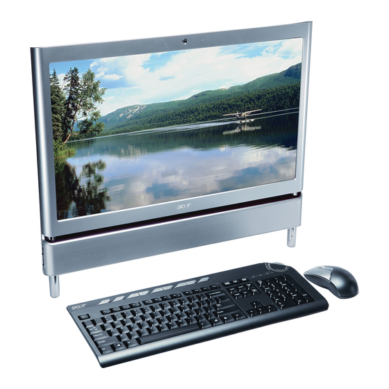
Page 14: Your Acer Computer Tour
Your Acer Computer tour After knowing your computer features, let us show you around your new computer. IMPORTANT:Your computer’s hardware options, port locations, and indicators may vary from this illustration. Front View Component Microphone HD webcam Display screen Acer TouchPortal... -
Page 15: Right View
Right View IMPORTANT:Your computer’s hardware options, port locations, and indicators may vary from this illustration. Component Headphone jack (white plug) Microphone jack (pink plug) Illumination Toggle Switch Memory card reader Optical Disk Drive Chapter 1 Icon Plug powered, analog front speakers, an external amplifier, or headphones into this jack. -
Page 16: Left View
Left View IMPORTANT:Your computer’s hardware options, port locations, and indicators may vary from this illustration. Component B-CAS reader USB 2.0 port Icon Subscription service available for select models only. Plug USB (Universal Serial Bus) devices (such as a USB external drive, printer, scanner, camera, keyboard, or mouse) into this port. -
Page 17: Rear View
Rear View IMPORTANT:Your computer’s hardware options, port locations, and indicators may vary from this illustration. Component Power connector Kensington™ lock slot USB ports Ethernet (network) jack Line-out/Speaker- out jack eSATA port TV Tuner IR port Chapter 1 Icon Plug the power cord into this connector. Secure your computer to an object by connecting a Kensington cable lock to this slot. -
Page 18: Using The Keyboard
Using the Keyboard The keyboard has several different types of keys and buttons as shown below. Fn key Windows key Feature Function keys Audio playback keys Windows key Fn key Application key Navigation keys Function keys Audio playback keys Application Icon Press these keys to start program actions. -
Page 19: Windows Keys
Windows Keys The keyboard has two keys that perform Windows-specific functions. Windows key Pressed alone, this key has the same effect as clicking on the Windows Start button; it launches the Start menu. It can also be used with other keys to provide a variety of functions: <... -
Page 20: Hardware Specifications And Configurations
Hardware Specifications and Configurations Processor Item CPU type Core Logic CPU Package CPU Core Voltage Specification Intel Core™2 Quad Processor* • Intel Core™2 Duo Processor* • Intel Pentium Processor* • Intel® Celeron® processor* • North Bridge (Eaglelake G45) • GTL+ interface (Front-side bus) •... - Page 21 CPU Temperature FAN off (°C) VGA Temperature FAN off (°C) Phoenix BIOS R01-A1 SPI interface to serial flash memory, SOP8 package 8 MB Cache Package Acer P/N Size KC.22201.DEM KC.52001.DEM KC.53001.DEM KC.54001.DEM 2 MB KC.63001.DEM 2 MB KC.65001.DEM 3 MB KC.73001.DE0 3 MB KC.74001.DE0...
- Page 22 Item Supported protocols BIOS password control System Memory Item Memory controller Memory size DIMM socket number Supports memory size per socket Supports maximum memory size Supports DIMM type Supports DIMM Speed Supports DIMM voltage Memory Combinations Slot 1 512MB 512MB 512MB 1024MB 1024MB...
- Page 23 NorthBridge Chipset Item Chipset Eaglelake G45 Features GTL+ interface (Front-side bus) • Support Intel Yorkfield/Wolfdale Processor • 800/1066/1333MHz transfer rate processor bus speed • SouthBridge Chipset Item Chipset ICH10 Features PCI bus Interface • Supports PCI bus at 33MHz • PCI Rev.2.3 specification support.
- Page 24 Item Chipset Features LAN Interface Item LAN Chipset Realtek RTL8111DL Supports LAN protocol 10/100/1000M Fast Ethernet LAN connector type RJ-45 LAN connector location Main Board Features • • • • • • • • • • • • • • •...
- Page 25 Item Sampling Rate Internal Microphone Chapter 1 Specification DACs with 97dB SNR • ADCs with 90dB SNR • Internal Speaker(5WX2) • Line out 5.1 Channel • Head Phone out , MIC In , Digital MIC In • Software Sound Volume Control •...
- Page 26 Chapter 1...
-
Page 27: System Utilities
System Utilities BIOS Setup Utility The BIOS Setup Utility is a hardware configuration program built into your computer’s BIOS (Basic Input/ Output System). Your computer is already properly configured and optimized, and you do not need to run this utility. However, if you encounter configuration problems, you may need to run Setup. -
Page 28: Information
Information The Information screen displays a summary of your computer hardware information. Info M a i n Advanced P r o c e s s o r T y p e P r o c e s s o r S p e e d S y s t e m M e m o r y : S y s t e m M a n u f a c t u r e r : P r o d u c t N a m e :... -
Page 29: Main
Main The Main screen allows the user to set the system time and date as well as enable and disable boot options. Info M a i n Advanced S y s t e m D a t e : S y s t e m T i m e : S y s t e m T i m e : S A T A P o r t 1 S A T A P o r t 1... -
Page 30: Sata Port
SATA Port 1 The SATA Port 1 screen allows the user to view and adjust SATA settings on Port 1. Info M a i n Advanced S A T A P o r t 1 T y p e : M u l t i - S e c t o r T r a n s f e r s : M u l t i - S e c t o r T r a n s f e r s : L B A M o d e C o n t r o l :... - Page 31 SATA Port 2 The SATA Port 2 screen allows the user to view and adjust SATA settings on Port 2. Info M a i n Advanced S A T A P o r t 4 T y p e : M u l t i - S e c t o r T r a n s f e r s : M u l t i - S e c t o r T r a n s f e r s : L B A M o d e C o n t r o l :...
- Page 32 SATA Port 4 The SATA Port 4 screen allows the user to view and adjust SATA settings on Port 4. Info M a i n Advanced S A T A P o r t 2 T y p e : M u l t i - S e c t o r T r a n s f e r s : M u l t i - S e c t o r T r a n s f e r s : L B A M o d e C o n t r o l :...
-
Page 33: Advanced
Advanced The Advanced screen allows the user to configure the various advanced BIOS options. Info M a i n Advanced A d v a n c e d C h i p s e t F e a t u r e s I n t e g r a t e d P e r i p h e r a l s I n t e g r a t e d P e r i p h e r a l s H e l p... -
Page 34: Advanced Chipset Features
Advanced Chipset Features The Advanced Chipset screen allows the user to configure chipset settings. Advanced A d v a n c e d C h i p s e t F e a t u r e s I n t e l E I S T : I n t e l E I S T : I n t e l X D B i t : I n t e l X D B i t :... -
Page 35: Integrated Peripherals
Integrated Peripherals The Integrated Peripherals screen allows the user to configure various display settings. Advanced I n t e g r a t e d P e r i p h e r a l s O n b o a r d S A T A C o n t r o l l e r : O n b o a r d S A T A C o n t r o l l e r : S A T A C o n t r o l l e r M o d e : S A T A C o n t r o l l e r M o d e :... -
Page 36: Security
Security The Security screen contains parameters that help safeguard and protect your computer from unauthorized use. Info M a i n Advanced S u p e r v i s o r P a s s w o r d I s : S u p e r v i s o r P a s s w o r d I s : U s e r P a s s w o r d I s : U s e r P a s s w o r d I s :... -
Page 37: Setting A Password
Setting a Password Follow these steps as you set the user or the supervisor password: Use the ↑ and ↓ keys to highlight the Set Supervisor Password parameter and press the Enter key. The Set Supervisor Password box appears: E n t e r N e w P a s s w o r d C o n f i r m N e w P a s s w o r d Type a password in the “Enter New Password”... -
Page 38: Changing A Password
Changing a Password Use the ↑ and ↓ keys to highlight the Set Supervisor Password parameter and press the Enter key. The Set Password box appears. E n t e r C u r r e n t P a s s w o r d E n t e r N e w P a s s w o r d C o n f i r m N e w P a s s w o r d Type the current password in the Enter Current Password field and press Enter. -
Page 39: Pc Health
PC Health The PC Health screen displays CPU/Chipset temperature information and contains customizable safety monitors for the CPU. Info M a i n Advanced C P U T e m p e r a t u r e : C P U T e m p e r a t u r e : C P U F a n S p e e d : C P U F a n S p e e d : C P U C o r e :... -
Page 40: Power
Power The Power screen contains parameters used for device power management. Info M a i n Advanced A C P I S u s p e n d M o d e : A C P I S u s p e n d M o d e : P o w e r O n b y R T C A l a r m : P o w e r O n b y R T C A l a r m : P o w e r O n b y O n b o a r d L A N :... -
Page 41: Boot
Boot This menu allows the user to decide the order of boot devices to load the operating system. Bootable devices includes the USB diskette drives, the onboard hard disk drive and the DVD drive. Info M a i n Advanced B o o t p r i o r i t y o r d e r : B o o t p r i o r i t y o r d e r : 1 : I n t e r n a l S S D :... -
Page 42: Exit
Exit The Exit screen allows you to save or discard any changes you made and quit the BIOS Utility. Info Main Advanced Exit Saving Changes Exit Saving Changes Exit Discarding Changes Exit Discarding Changes Load Setup Defaults Load Setup Defaults Discard Changes Discard Changes Save Changes... -
Page 43: Machine Disassembly And Replacement
Machine Disassembly and Replacement IMPORTANT:The outside housing and color may vary from the mass produced model. This chapter contains step-by-step procedures on how to disassemble the computer for maintenance and troubleshooting. Disassembly Requirements To disassemble the computer, you need the following tools: Wrist grounding strap and conductive mat for preventing electrostatic discharge •... -
Page 44: Disassembly Process
Disassembly Process Disassembly Flowchart Turn off power and disconnect all cables before proceeding Remove Remove Hinge Cover RAM Cover Remove Remove Rear Covers Back Cover Remove HDD Module Remove Hinge Remove Home Button Board Remove Power Supply Remove Card Reader Board Remove Audio Board... -
Page 45: Removing The Ram Cover
Removing the RAM Cover 1. See “Pre-disassembly Instructions” on page 33. 2. Apply pressure to one end of the RAM Cover, while pulling up with the opposite hand as shown. 3. Lift the RAM Cover clear of the device. Chapter 3... -
Page 46: Removing The Hinge Cover
Removing the Hinge Cover 1. See “Removing the RAM Cover” on page 35. 2. Grasp the Hinge Cover with both hands. 3. Lift the Hinge Cover clear of the device. Chapter 3... -
Page 47: Removing The Ram
Removing the RAM 1. See “Removing the Hinge Cover” on page 36. 2. Lift the RAM Shielding clear of the device. 3. Unlock the latches on either side of the RAM by pressing down as shown. There is an audible click when the latch is unlocked. -
Page 48: Removing The Rear Covers
Removing the Rear Covers 1. See “Removing the RAM” on page 37. 2. Remove the six (6) screws that secure the Rear Covers. Step Rear Covers 3. Use both hands to gently push the rear cover outward from the device as shown. 4. -
Page 49: Removing The Back Cover
Removing the Back Cover 1. See “Removing the Rear Covers” on page 38. 2. Remove the fourteen (14) screws securing the Back Cover. Step Back Cover 3. Use both hands to move the Hinge up into the stand position. There is an audible click when the Hinge is locked in position. - Page 50 4. Place one hand firmly on the Back Cover. Use the opposite hand to pry the Bezel away, working from one corner to the other as shown. Repeat this step until all guides along the bottom of the device are unlocked. 5.
-
Page 51: Removing The Hinge
Removing the Hinge 1. See “Removing the Back Cover” on page 39. 2. Replace the Hinge to the carry position. 3. Remove the six (6) screws securing the Hinge. Step Hinge 4. Lift the Hinge clear of the device. Chapter 3 Size Quantity Screw Type... -
Page 52: Removing The Back Frame
Removing the Back Frame 1. See “Removing the Hinge” on page 41. 2. Unstick the EMI Cable Mylar as shown. CAUTION: Do not remove the EMI Cable completely; the cable is still attached to the device. 3. Disconnect the CPU Power Cable (A), the SATA Power Cable (B), and the HDD Power Cable (C) as shown: Chapter 3... - Page 53 4. Remove the nine (9) screws securing the Back Frame. Step Size Quantity Screw Type Back Frame 5. Lift one end of the Back Frame as shown. 6. Carefully unhook the guide at the opposite end before lifting away completely. Chapter 3...
-
Page 54: Removing The Power Supply
Removing the Power Supply 1. See “Removing the Back Frame” on page 42. 2. Remove two (2) screws securing the Power Supply as shown. Step Power Supply 3. Lift the Power Supply clear of the device. Size Quantity Screw Type Chapter 3... -
Page 55: Removing The Hdd Module
Removing the HDD Module 1. See “Removing the Power Supply” on page 44. 2. Disconnect the HDD Cable as shown. 3. Remove two (2) screws securing the HDD Module. Step HDD Module 4. Slide the HDD Module out of the flanges. Chapter 3 Size Quantity... -
Page 56: Removing The B-Cas Board
Removing the B-CAS Board 1. See “Removing the HDD Module” on page 45. 2. Remove the three (3) screws securing the B-CAS Board. Step B-CAS 3. Lift out the B-CAS Board and turn it over. Disconnect the B-CAS Board Cable underneath. Size Quantity Screw Type... -
Page 57: Removing The Ssd Module
Removing the SSD Module 1. See “Removing the B-CAS Board” on page 46. 2. Remove one (1) screw securing the SSD Module as shown. Step SSD Module 3. Slide the SSD out of the flange. Chapter 3 Size Quantity Screw Type... -
Page 58: Removing The Control Board
Removing the Control Board 1. See “Removing the SSD Module” on page 47. 2. Disconnect three (3) cables on the Control Board as shown 3. Remove the two (2) screws securing the Control Board as shown. Step Control Board 4. Lift the Control Board clear of the device. Size Quantity Screw Type... -
Page 59: Removing The Card Reader Board
Removing the Card Reader Board 1. See “Removing the Control Board” on page 48. 2. Disconnect the Card Reader Board Cable. 3. Remove three (3) securing screws from the Card Reader Board. Step Card Reader Board 4. Lift the Card Reader Board clear of the device. Chapter 3 Size Quantity... -
Page 60: Removing The Audio Board
Removing the Audio Board 1. See “Removing the Card Reader Board” on page 49. 2. Disconnect the Audio Board Cable. 3. Remove one (1) screw from the Audio Board. Step Audio Board 4. Carefully remove the Audio Board by separating it from the bracket and three guide pins as shown. Size Quantity Screw Type... -
Page 61: Removing The Odd Button Board
Removing the ODD Button Board 1. See “Removing the Audio Board” on page 50. 2. Remove one (1) securing screw from the ODD Button Board. Step ODD Button Board 3. Disconnect one (1) cable from the ODD Button Board. 4. Lift the ODD Button Board clear of the device. Chapter 3 Size Quantity... -
Page 62: Removing The Odd Module
Removing the ODD Module 1. See “Removing the ODD Button Board” on page 51. 2. Remove two (2) securing screws from the ODD Module. Step ODD Module 3. Slide the ODD Module out of the flange. Size Quantity Screw Type Chapter 3... -
Page 63: Removing The Inverter Board
Removing the Inverter Board 1. See “Removing the ODD Module” on page 52. 2. Carefully disconnect both Inverter Cables from either side of the Inverter Board. 3. Disconnect the Mainboard Cable as shown. 4. Remove three (3) securing screws from the Inverter Board. Step Inverter Board Chapter 3... - Page 64 5. Lift the Inverter Board clear of the device. Chapter 3...
-
Page 65: Removing The Home Button Board
Removing the Home Button Board 1. See “Removing the Inverter Board” on page 53. 2. Remove one (1) securing screw from the Home Button Board. Step Home Button Board 3. Disconnect one (1) cable from the Home Button Board. 4. Lift the Home Button Board away as shown. Chapter 3 Size Quantity... -
Page 66: Removing The Web Camera Board
Removing the Web Camera Board 1. See “Removing the Home Button Board” on page 55. 2. Remove two (2) screws securing the Web Camera Board as shown. Step Web Camera Board SCREW M2.0*4 3. Gently lift out the Web Camera Board and turn it over. CAUTION: Do not use excessive force when removing the Web Camera Board. -
Page 67: Removing The Tv Tuner Board
Removing the TV Tuner Board 1. See “Removing the Web Camera Board” on page 56. 2. Disconnect one (1) cable from the TV Tuner Board. 3. Remove one (1) securing screw from the TV Tuner Board. Step TV Tuner Board 4. -
Page 68: Removing The Wlan Board
Removing the WLAN Board 1. See “Removing the TV Tuner Board” on page 57. 2. Disconnect two (2) cables from the WLAN Board as shown. 3. Remove one (1) securing screw from the WLAN Board. Step WLAN Board 4. Lift the WLAN Board clear of the device. Size Quantity Screw Type... -
Page 69: Removing The Cpu Fan
Removing the CPU Fan 1. See “Removing the WLAN Board” on page 58. 2. Disconnect the CPU fan cable from the Mainboard. 3. Remove two (2) securing screws from the Fan. Step CPU Fan SCREW M2.5*6 4. Lift the CPU Fan clear of the device. Chapter 3 Size Quantity... -
Page 70: Removing The Thermal Module
Removing the Thermal Module 1. See “Removing the CPU Fan” on page 59. 2. Remove six (6) captive screws from the Thermal Module in ascending order from 1 to 6. Step Thermal Module 3. Lift the Thermal Module clear of the device. Size Quantity Screw Type... -
Page 71: Removing The Cpu
Removing the CPU 1. See “Removing the Thermal Module” on page 60. 2. Push the CPU latch down (1) and out (2) to unlock the processor housing. 3. Lift the cover of the housing. 4. Remove the CPU. Chapter 3... -
Page 72: Removing The Mainboard Cables
Removing the Mainboard Cables 1. See “Removing the CPU” on page 61. 2. Remove seventeen (17) cables from the Mainboard as shown. Item Description LVDS Cable CCD Cable Inverter Cable MIC Cable ODD Button Cable Home Button Cable Card Reader Cable IR Cable Touch Screen Audio Cable... -
Page 73: Removing The Mainboard
Removing the Mainboard 1. See “Removing the Mainboard Cables” on page 62. 2. Remove five (5) securing screws from the Mainboard as shown. Step Mainboard SCREW M 2.5*4MM 3. Carefully lift the Mainboard clear of the device. Chapter 3 Size Quantity Screw Type... -
Page 74: Removing The Lcd Assembly
Removing the LCD Assembly 1. See “Removing the Mainboard” on page 63. 2. Release five (5) cable locks as shown. 3. Disconnect the Home Button Cable. Chapter 3... - Page 75 4. Remove the LVDS Mylar (1) and disconnect the cable (2) as shown. 5. Disconnect the left and right Control board Cables. Chapter 3...
- Page 76 6. Remove four (4) securing screws from the LCD Bracket. Step LCD Bracket SCREW M2.5*4 7. Remove nine (9) securing screws from the LCD Bezel. Step LCD Bezel SCREW M2.5*4 Size Quantity Size Quantity Screw Type Screw Type Chapter 3...
- Page 77 8. Lift the LCD Assembly clear of the device. WARNING:When lifting the LCD Assembly, do not touch the Camera Modules located at the top left and top right corners of the device. Doing so will damage the touch screen function. Chapter 3...
-
Page 78: Removing The Lcd Bracket
Removing the LCD Bracket 1. See “Removing the LCD Assembly” on page 64. 2. Place the LCD Assembly on an anti-static mat so the touch sensors are elevated above the work surface. WARNING:Do not place the LCD Panel face down without an anti-static mat underneath. The touch sensors located at the top left and top right corners will be damaged if the LCD Panel is placed face down. -
Page 79: Reassembly Procedure
Reassembly Procedure Replacing the LCD Bracket 1. Replace one side of the LCD Bracket (1), while using the opposite hand to pull the cables through the frame (2). Make sure the frame is fitted securely on top of the panel. 2. -
Page 80: Replacing The Lcd Assembly
Replacing the LCD Assembly 1. Carefully place the LCD Assembly in the LCD Bezel. 2. Secure the LCD Bezel using nine (9) screws. Chapter 3... - Page 81 3. Secure the LCD Bracket using four (4) screws. 4. Connect the left and right Control Board Cables. Chapter 3...
- Page 82 5. Replace the LVDS Mylar (1) and connect the cable (2). 6. Connect the Home Button Cable 7. Lock the five (5) cable locks as shown. Chapter 3...
-
Page 83: Replacing The Mainboard
Replacing the Mainboard 1. Carefully replace the Mainboard, while lining up the six (6) guide pins underneath. 2. Secure the Mainboard in place using five (5) screws as shown. Chapter 3... -
Page 84: Replacing The Mainboard Cables
Replacing the Mainboard Cables 1. Secure the Mainboard by connecting seventeen (17) cables. Item Description LVDS Cable CCD Cable Inverter Cable MIC Cable ODD Button Cable Home Button Cable Card Reader Cable IR Cable Touch Screen Audio Cable TV Tuner Cable USB Cable Speaker Cable SATA Cable... -
Page 85: Replacing The Cpu
Replacing the CPU 1. Place the CPU in the CPU housing. 2. Close the cover of the housing. 3. Push the CPU latch down (1) and in (2) to lock the processor housing. Chapter 3... -
Page 86: Replacing The Thermal Module
Replacing the Thermal Module IMPORTANT:Ensure a heat pad is in place before replacing the Thermal Module. 1. Replace the Thermal Module as shown. 2. Secure the module by tightening six (6) captive screws in ascending order from 1 to 6. Chapter 3... -
Page 87: Replacing The Cpu Fan
Replacing the CPU Fan 1. Using both hands, align the screw holes on the fan and LCD Module and place the fan on the Thermal Module. 2. Connect the CPU Fan cable to the Mainboard connector. 3. Secure the Fan using two (2)screws as shown. Chapter 3... -
Page 88: Replacing The Wlan Board
Replacing the WLAN Board 1. Push the WLAN Board into the slot. 2. Secure the WLAN Board using one (1) screw as shown. 3. Connect two (2) cables to secure the WLAN Board. NOTE: The gray and black cables must be attached to the proper connector to function properly. Chapter 3... -
Page 89: Replacing The Tv Tuner Board
Replacing the TV Tuner Board 1. Push the TV Tuner Board into the slot. 2. Secure the TV Tuner Board using one (1) screw as shown. 3. Connect one (1) cable to secure the TV Tuner Board. Chapter 3... -
Page 90: Replacing The Web Camera Board
Replacing the Web Camera Board 1. Connect the cable underneath the Web Camera board. CAUTION: Do not use excessive force when handling the Web Camera Board. 2. Turn the Board over and place it in the device. 3. Secure the Web Camera Board using two (2) screws as shown. Chapter 3... -
Page 91: Replacing The Home Button Board
Replacing the Home Button Board 1. Replace the Home Button Board, while lining up the guide pin underneath. 2. Secure the Home Button Board using one screw. 3. Connect one cable to secure the Home Button Board. Chapter 3... -
Page 92: Replacing The Inverter Board
Replacing the Inverter Board 1. Replace the Inverter Board as shown. 2. Secure the Inverter Board using three (3) screws. 3. Connect the Mainboard cable to the Inverter Board as shown. Chapter 3... - Page 93 4. Connect the cables on either side of the Inverter Board. Chapter 3...
-
Page 94: Replacing The Odd Module
Replacing the ODD Module 1. Slide the ODD Module into the flange. 2. Secure the ODD Module using two (2) screws. Chapter 3... -
Page 95: Replacing The Odd Button Board
Replacing the ODD Button Board 1. Replace the ODD Button Board while lining up the guide pin underneath. 2. Secure the ODD Button Board using one (1) screw. 3. Connect one (1) cable to secure the ODD Button Board as shown. Chapter 3... -
Page 96: Replacing The Audio Board
Replacing the Audio Board 1. Replace the Audio Board by lining up the ports with the bracket and three (3) guide pins as shown. 2. Secure the Audio Board using one (1) screw. 3. Connect the Audio Board Cable. Chapter 3... -
Page 97: Replacing The Card Reader Board
Replacing the Card Reader Board 1. Replace the Card Reader Board. 2. Secure the Card Reader Board using three (3) screws. 3. Connect the Card Reader Board Cable. Chapter 3... -
Page 98: Replacing The Control Board
Replacing the Control Board 1. Replace the Control Board. 2. Secure the Control Board using two (2) screws. 3. Connect three (3) cables to secure the Control Board as shown. Chapter 3... -
Page 99: Replacing The Ssd
Replacing the SSD 1. Slide the SSD into the flange. 2. Secure the SSD using one (1) screw as shown. Chapter 3... -
Page 100: Replacing The B-Cas Board
Replacing the B-CAS Board 1. Connect the cable underneath the B-CAS Board. 2. Turn the B-CAS Board over and replace it. 3. Install the USB and HDD grounding cables as shown. Chapter 3... - Page 101 4. Secure the B-CAS Board with three (3) screws. Chapter 3...
-
Page 102: Replacing The Hdd Module
Replacing the HDD Module 1. Slide the HDD Module into the flanges. 2. Secure the HDD Module using two (2) screws. 3. Connect the HDD Cable as shown. Chapter 3... -
Page 103: Replacing The Power Supply
Replacing the Power Supply 1. Replace the Power Supply as shown. 2. Secure the Power Supply using two (2) screws. Chapter 3... -
Page 104: Replacing The Back Frame
Replacing the Back Frame 1. Place one end of the Back Frame (1) in the device as shown. Line up the guide (2) before replacing completely. 2. Secure the Back Frame using nine (9) screws. 3. Connect the CPU Power Cable (A), the SATA Power Cable(B), and the HDD Power Cable (C) Chapter 3... - Page 105 4. Attach the EMI Cable Mylar to the Back Frame as shown. Chapter 3...
-
Page 106: Replacing The Hinge
Replacing the Hinge 1. Replace the Hinge, noting the guide pin that must be lined up. 2. Secure the Hinge using six (6) screws. Chapter 3... -
Page 107: Replacing The Back Cover
Replacing the Back Cover 1. Snap the Back Cover into place using both hands. Make sure that all the guides have been securely locked. 2. Move the Hinge down into the carry position. There is an audible click when the Hinge is locked in position. Chapter 3... - Page 108 3. Secure the Back Cover using fourteen (14) screws. Chapter 3...
-
Page 109: Replacing The Rear Covers
Replacing the Rear Covers 1. Replace the Rear Cover by pushing inward as shown 2. Repeat the previous step for the remaining Rear Cover. 3. Secure the Rear Covers using six (6) screws. Chapter 3... -
Page 110: Replacing The Ram
Replacing the RAM 1. Firmly place each Ram into its slot until a click is heard. Make sure the latches are in the lock position. 2. Replace the Ram Shielding. Chapter 3... -
Page 111: Replacing The Hinge Cover
Replacing the Hinge Cover 1. Grasp the Hinge Cover with both hands. 2. Gently push the Hinge Cover down until it snaps into place. Chapter 3... -
Page 112: Replacing The Ram Cover
Replacing the RAM Cover 1. Line up one end of the RAM Cover with the device as shown. 2. Push down with both hands until the cover snaps into place. Chapter 3... -
Page 113: Troubleshooting
Common Problems Use the following procedure as a guide for computer problems. NOTE: The diagnostic tests are intended to test only Acer products. Non-Acer products, prototype cards, or modified options can give false errors and invalid system responses. Obtain the failing symptoms in as much detail as possible. -
Page 114: Odd Failure
ODD Failure If an Optical Disk Drive failure is determined, use the following flowchart to determine the required action: DVD does not cable connection ODD Not Operating Correctly If the ODD exhibits any of the following symptoms it may be faulty: Audio CDs do not play when loaded •... - Page 115 Double-click DVD/CD-ROM drives. If the device displays a down arrow, right-click on the device and click Enable. Check that there are no yellow exclamation marks against the items in lDE ATA/ATAPI controllers. If a device has an exclamation mark, right-click on the device and uninstall and reinstall the driver. Check that there are no yellow exclamation marks against the items in DVD/CD-ROM drives.
- Page 116 Click Properties and select the Advanced Settings tab. Ensure that the Enable DMA box is checked and click OK. Repeat for the other ATA Devices shown if applicable. Drive Not Detected If Windows cannot detect the drive, perform the following actions one at a time to correct the problem. Restart the computer and press F2 to enter the BIOS Utility.
-
Page 117: Wireless Failure
Wireless Failure If the wireless functionality fails, use the following flowchart to determine the required action: Chapter 4 START Wirelss function failure Check WLAN Reconnect cable connection cable correctly Check WLAN Replace module WLAN module Replace Mainboard Close Close Close... -
Page 118: Camera Failure
Camera Failure If the camera functionality fails, use the following flowchart to determine the required action: function failure Check camera cable connection Check camera START Camera Reconnect cable correctly Replace camera module module Replace Mainboard Close Close Close Chapter 4... -
Page 119: Speaker Failure
Speaker Failure If the internal speaker fails, use the following flowchart to determine the required action: cable connection Sound Problems If sound problems are experienced, perform the following actions one at a time to correct the problem. Reboot the computer. Navigate to Start Control Panel the Device Manager to determine that:... - Page 120 Restore system and file settings from a known good date using System Restore. If the issue is not fixed, repeat the preceding steps and select an earlier time and date. 10. Reinstall the Operating System. 11. If the Issue is still not resolved, see “Online Support Information” on page 175. Chapter 4...
-
Page 121: Lcd Failure
LCD Failure If the integrated LCD display fails, use the following flowchart to determine the required action: Check LCD cable connected Check LCD cable is good Check LCD module is good No POST or Video If the POST or video doesn’t display, perform the following actions one at a time to correct the problem. Make sure the computer has power by checking at least one of the following occurs: Fans start up •... - Page 122 Abnormal Video Display If video displays abnormally, perform the following actions one at a time to correct the problem. Reboot the computer. If permanent vertical/horizontal lines or dark spots display in the same location, the LCD is faulty and should be replaced. See “Disassembly Process” on page 42. If extensive pixel damage is present (different colored spots in the same locations on the screen), the LCD is faulty and should be replaced.
-
Page 123: General Troubleshooting Issues
General Troubleshooting Issues Computer Shutsdown Intermittently If the system powers off at intervals, perform the following actions one at a time to correct the problem. Check the power cable is properly connected to the computer and the electrical outlet. Remove any extension cables between the computer and the outlet. Remove any surge protectors between the computer and the electrical outlet. -
Page 124: Hdd Not Operating Correctly
HDD Not Operating Correctly If the HDD does not operate correctly, perform the following actions one at a time to correct the problem. Disconnect all external devices. Run a complete virus scan using up-to-date software to ensure the computer is virus free. Run the Windows 7 Startup Repair Utility: insert the Windows 7 Operating System DVD in the ODD and restart the computer. - Page 125 11. Remove and reinstall the mouse driver. 12. Check the Device Manager to determine that: The device is properly installed. There are no red Xs or yellow exclamation marks. • There are no device conflicts. • No hardware is listed under Other Devices. •...
-
Page 126: Intermittent Problems
NOTE: Verify that the power supply being used at the time of the failure is operating correctly. Power-off the computer. Visually check for damage. If any problems are found, replace the FRU. Remove or disconnect all of the following devices: Non-Acer devices • Printer, mouse, and other external devices •... -
Page 127: Jumper And Connector Locations
Jumper and Connector Locations Top View Item Description CPU/Processor socket DDR3 DDR3 SODIMM sockets CPU fan connector MXM connector SSD connector Touch Touch screen connector Screen TV connector Speaker Speaker connector BCAS BCAS connector Webcam Webcam connector Chapter 5 Item Description WLAN Wireless LAN card connector... -
Page 128: Bottom View
Bottom View Item Description RTC battery socket Chapter 5... -
Page 129: Clearing Password Check And Bios Recovery
This section provide you the standard operating procedures of clearing password and BIOS recovery for Aspire Z5600/Z5610 Series. Aspire Z5600/Z5610 Series provides one Hardware Open Gap on main board for clearing password check, and one Hotkey for enabling BIOS Recovery. -
Page 130: Bios Recovery By Crisis Disk
BIOS Recovery by Crisis Disk BIOS Recovery Boot Block: BIOS Recovery Boot Block is a special block of BIOS. It is used to boot up the system with minimum BIOS initialization. Users can enable this feature to restore the BIOS firmware to a successful one once the previous BIOS flashing process failed. - Page 131 Steps for BIOS Recovery by Crisis Disk: Before doing this, a Crisis Diskette should be prepared ready in hand. The Crisis Diskette could be made by executing the Crisis Disk program in another system with Windows XP OS. Follow the steps below: 1.
- Page 132 7. Click the (N) button when prompted to complete the process. 8. Insert the Crisis Disk in to the USB floppy drive attached to the BIOS flash failed system. 9. In the power-off state, unplug the AC power and hold Fn+Esc then plug the AC power in. 10.
-
Page 133: Fru (Field Replaceable Unit) List
Guide. For ACER AUTHORIZED SERVICE PROVIDERS, your Acer office may have a DIFFERENT part number code from those given in the FRU list of this printed Service Guide. You MUST use the local FRU list provided by your regional Acer office to order FRU parts for repair and service of customer machines. -
Page 134: Aspire Z5600/Z5610 Series Exploded Diagrams
Aspire Z5600/Z5610 Series Exploded Diagrams Main Assembly Hinge Cover Rear Cover (L) Rear Cover (R) Ram Cover Hinge Power Supply ODD Module Main Board Card Reader Board Audio Board LCD Frame LCD Touch Panel Description 42.SCY07.002 60.SCY07.005 60.SCY07.006 33.SCY07.003 60.SCY07.007 60.SCY07.002... - Page 135 Front Bezel Back Cover Back Frame Fan Module UMA B-CAS Card Chapter 6 Description 60.SCY07.001 60.SCY07.002 33.SCY07.002 23.SCY07.003 55.SCY07.005 Acer P/N...
-
Page 136: Fru List
MXM 3.0 Type A w/ Samsung K4W1G1646D-EJ11 BOARD AUDIO BOARD CARD READER BOARD POWER BOARD ODD BOARD B CAS BOARD HOME BUTTON BOARD INVERTER BOARD DA-4A12-QT03L INVERTER BOARD IV40157/T-LF WLAN Description ACER PART NO. VG.M9206.008 VG.M9606.011 55.SCY07.001 55.SCY07.002 55.SCY07.003 55.SCY07.004 55.SCY07.005 55.SCY07.006 19.SCY07.001 19.SCY07.002 Chapter 6... - Page 137 CABLE - AUDIO/B TO MB LVDS CABLE HDD CABLE ODD CABLE CABLE - CONTROL BORAD TO SENSOR/R CABLE - CONTROL BORAD TO SENSOR/L IR CABLE Chapter 6 Description ACER PART NO. NI.10200.031 NI.10200.015 BT.14500.001 PC.13400.009 TU.10500.052 TU.10500.051 RT.11300.005 RT.11300.006 RV.RWS07.001 27.SCY07.001...
- Page 138 BACK COVER ASSY RED - UMA RAM COVER - RED HINGE COVER REAR COVER SILVER - LEFT W/O B-CAS REAR COVER SILVER - LEFT W/B CAS REAR COVER SILVER - RIGHT LCD FRAME Description ACER PART NO. 50.SCY07.008 50.SCY07.009 50.SCY07.010 50.SCY07.011 50.SCY07.012 50.SCY07.013 50.SCY07.014 50.SCY07.015...
- Page 139 SPEAKER SET ODD BRACKET HDD BRACKET MXM BRACKET Heat SINK CPU HEATSINK VGA HEATSINK FAN MODULE - UMA FAN MODULE - MXM CPU/PROCESSOR Chapter 6 Description ACER PART NO. 33.SCY07.002 33.SCY07.003 60.SCY07.007 23.SCY07.005 33.SCY07.004 33.SCY07.005 33.SCY07.006 23.SCY07.001 23.SCY07.002 23.SCY07.003 23.SCY07.004...
- Page 140 Traditional Chinese with new color AC-MT-010 Keyboard CHICONY KG-0766 RF2.4 104KS Silver Simplified Chinese with new color AC-MT-010 Keyboard CHICONY KG-0766 RF2.4 104KS Silver US International with new color AC-MT-010 Description ACER PART NO. KC.22201.DEM KC.52001.DEM KC.53001.DEM KC.54001.DEM KC.63001.DEM KC.65001.DEM KC.73001.DE0...
- Page 141 Keyboard CHICONY KG-0766 RF2.4 104KS Silver Greek with new color AC-MT-010 Keyboard CHICONY KG-0766 RF2.4 105KS Silver Danish with new color AC-MT-010 Keyboard CHICONY KG-0766 RF2.4 104KS Silver Czech with new color AC-MT-010 Chapter 6 Description ACER PART NO. KB.RF403.249 KB.RF403.250 KB.RF403.251 KB.RF403.252 KB.RF403.253 KB.RF403.254 KB.RF403.255 KB.RF403.256...
- Page 142 ODD SONY Super-Multi DRIVE 12.7mm Slot LabelFlash 8X AD-7643S LF W/O bezel SATA w/ Win7 MAINBOARD MAINBAORD UMA INTEL G45 ICH10 W/O 1394 W/O CPU RAM MAINBAORD DIS INTEL G45 ICH11 W/O 1394 W/O CPU Description ACER PART NO. KB.RF403.274 KB.RF403.275 KB.RF403.276 KB.RF403.277 KB.RF403.278 KB.RF403.280 KB.RF403.281...
-
Page 143: Screw List
SCREW M2.0*6.0-I-NI-NYLOK IRON SCREW M2.5*4.0-I(NI)(NYLOK)IRON SCREW M2.5*6.0-I(NI)(NYLOK) SCREW M2.5*8-I(BNI)(NYLOK)IRON SCREW M4.0*8.0-T(BNI)(NYLOK) IRON SCREW T1.7*4.0-I(BZN) SCREW M2.5*4-I (NI,NYLOK) IRON SCREW M3.0*5.0-P(BNI)NYLOK IRON SCREW 6-32UNC*5-B(NYLOK)IRON Chapter 6 Description Description ACER PART NO. KN.1GB03.032 KN.1GB0B.030 KN.1GB0G.024 KN.1GB0H.012 KN.2GB03.016 KN.2GB0B.014 KN.2GB0G.015 KN.2GB0H.006 6K.SCY07.001 6K.SCY07.002 PY.25009.012 PY.2500B.005... - Page 144 Chapter 6...
- Page 145 Chapter 6...
-
Page 146: Model Definition And Configuration
Model Definition and Configuration Aspire Z5600/Z5610 Series Model Name AZ5600 EMEA AZ5600 EMEA AZ5600 AZ5600 AZ5600 AZ5600 AZ5600 AZ5600 AMEX AZ5600 AZ5600 GCTWN AZ5600 Appendix A Country Acer Part no Netherlands PW.SC902.027 Netherlands PW.SC902.027 India PW.SC902.028 India PW.SC902.028 Singapore PW.SC902.013 Singapore PW.SC902.013... - Page 147 AZ5600 AZ5600 AZ5600 AZ5600 CHINA ACCN AZ5600 AZ5600 AZ5600 AZ5600 AZ5600 AZ5600 AZ5600 ASSSB AZ5600 ASSSB AZ5600 ASSSB Country Acer Part no Thailand PW.SC902.021 Thailand PW.SC902.021 Japan PW.SC902.024 China PW.SC902.020 Vietnam PW.SC902.019 Vietnam PW.SC902.019 Vietnam PW.SC902.019 Thailand PW.SC902.018 Thailand PW.SC902.018 Thailand PW.SC902.018...
- Page 148 AZ5600 APHI AZ5600 APHI AZ5600 APHI AZ5600 AZ5600 AZ5600 AZ5600 AZ5600 AZ5600 AZ5600 AZ5600 AZ5600 AZ5600 Appendix A Country Acer Part no Philippines PW.SC902.016 Philippines PW.SC902.016 Philippines PW.SC902.016 Indonesia PW.SC902.015 Indonesia PW.SC902.015 Indonesia PW.SC902.015 India PW.SC902.014 India PW.SC902.014 India PW.SC902.014 Australia/ PW.SC902.012...
- Page 149 AZ5600 AZ5600 GCTWN AZ5600 AZ5600 EMEA AZ5600 EMEA AZ5600 EMEA AZ5600 AZ5600 AZ5610 EMEA AZ5610 EMEA AZ5610 EMEA Country Acer Part no Australia/ PW.SC902.011 Zealand Australia/ PW.SC902.011 Zealand Taiwan PW.SC902.009 USA/ S1.SC902.004 Canada S1.SC902.003 S1.SC902.003 S1.SC902.003 USA/ S1.SC902.002 Canada USA/ S1.SC902.001...
- Page 150 AZ5610 EMEA AZ5610 EMEA AZ5610 EMEA AZ5610 EMEA AZ5610 EMEA AZ5610 EMEA AZ5610 EMEA AZ5610 EMEA Appendix A Country Acer Part no PW.SCY02.019 PW.SCY02.023 PW.SCY02.023 Germany PW.SCY02.017 Germany PW.SCY02.017 PW.SCY02.019 PW.SCY02.023 Russia PW.SCY02.067 Russia PW.SCY02.066 Africa/North PW.SCY02.065 Africa Africa/North PW.SCY02.064...
- Page 151 EMEA AZ5610 EMEA AZ5610 EMEA AZ5610 EMEA AZ5610 EMEA AZ5610 EMEA AZ5610 EMEA AZ5610 EMEA AZ5610 EMEA Country Acer Part no Spain PW.SCY02.063 PW.SCY02.024 PW.SCY02.024 PW.SCY02.024 Ukraine PW.SCY02.025 Ukraine PW.SCY02.026 PW.SCY02.034 PW.SCY02.034 PW.SCY02.034 Germany PW.SCY02.033 Description AZ5610 EMEA001 W7HP64R11a/ C2QQ8200s/U2GBIII13*4/D1500GB7.2KS*1/ NSM8XSLFSLOT/B23/vga/802.11bgn/...
- Page 152 AZ5610 EMEA AZ5610 EMEA AZ5610 EMEA AZ5610 EMEA AZ5610 EMEA AZ5610 EMEA AZ5610 EMEA AZ5610 EMEA Appendix A Country Acer Part no Germany PW.SCY02.033 Nordic PW.SCY02.062 Russia PW.SCY02.061 Spain PW.SCY02.036 Spain PW.SCY02.036 Saudi/ PW.SCY02.037 Levant/ Egypt Italy PW.SCY02.005 Germany PW.SCY02.040 Germany PW.SCY02.040...
- Page 153 AZ5610 EMEA AZ5610 EMEA AZ5610 EMEA AZ5610 EMEA AZ5610 EMEA AZ5610 EMEA AZ5610 EMEA AZ5610 EMEA AZ5610 EMEA Country Acer Part no Netherlands PW.SCY02.041 Russia PW.SCY02.046 Switzerland PW.SCY02.047 Belgium PW.SCY02.048 Belgium PW.SCY02.048 Luxembourg PW.SCY02.049 Luxembourg PW.SCY02.049 Saudi/ PW.SCY02.051 Levant/ Egypt Switzerland PW.SCY02.052...
- Page 154 AZ5610 EMEA AZ5610 EMEA AZ5610 EMEA AZ5610 EMEA AZ5610 EMEA AZ5610 EMEA AZ5610 EMEA AZ5610 EMEA Appendix A Country Acer Part no Bulgaria/ PW.SCY02.042 Latvia/ Lithuania/ Estonia Bulgaria/ PW.SCY02.043 Latvia/ Lithuania/ Estonia Bulgaria/ PW.SCY02.043 Latvia/ Lithuania/ Estonia Bulgaria/ PW.SCY02.053 Latvia/...
- Page 155 EMEA AZ5610 EMEA AZ5610 EMEA AZ5610 AZ5610 AZ5610 AZ5610 EMEA AZ5610 EMEA AZ5610 AZ5610 AZ5610 EMEA AZ5610 EMEA Country Acer Part no Russia PW.SCY02.059 Belgium PW.SCY02.057 Belgium PW.SCY02.057 Singapore PW.SCY02.007 Singapore PW.SCY02.007 Singapore PW.SCY02.007 Russia PW.SCY02.050 Russia PW.SCY02.045 Indonesia PW.SCY02.044 Indonesia PW.SCY02.044...
- Page 156 AZ5610 EMEA AZ5610 APHI AZ5610 APHI AZ5610 APHI AZ5610 AZ5610 AZ5610 AZ5610 AZ5610 AZ5610 AZ5610 AZ5610 Appendix A Country Acer Part no Saudi/ PW.SCY02.038 Levant/ Egypt Philippines PW.SCY02.035 Philippines PW.SCY02.035 Philippines PW.SCY02.035 USA/ PW.SCY02.032 Canada Japan PW.SCY02.031 Thailand PW.SCY02.030 Thailand PW.SCY02.030...
- Page 157 Model Name AZ5610 AZ5610 AZ5610 AZ5610 AZ5610 AZ5610 AZ5610 EMEA AZ5610 EMEA AZ5610 GCTWN AZ5610 AZ5610 AZ5610 Country Acer Part no Australia/ PW.SCY02.028 Zealand Australia/ PW.SCY02.028 Zealand Australia/ PW.SCY02.028 Zealand Australia/ PW.SCY02.027 Zealand Australia/ PW.SCY02.027 Zealand Australia/ PW.SCY02.027 Zealand Germany PW.SCY02.021...
- Page 158 AZ5610 EMEA AZ5610 CHINA ACCN AZ5610 AZ5610 AZ5610 AZ5610 AZ5610 AZ5610 AZ5610 AZ5610 AZ5610 AZ5610 GCTWN Appendix A Country Acer Part no France PW.SCY02.018 France PW.SCY02.018 China PW.SCY02.016 Vietnam PW.SCY02.015 Thailand PW.SCY02.014 Thailand PW.SCY02.014 Vietnam PW.SCY02.015 Thailand PW.SCY02.014 Vietnam PW.SCY02.015 Australia/ PW.SCY02.013...
- Page 159 Name AZ5610 GCTWN AZ5610 AZ5610 AZ5610 AZ5610 AZ5610 AZ5610 AZ5610 AZ5610 APHI AZ5610 APHI AZ5610 APHI AZ5610 AZ5610 Country Acer Part no Taiwan PW.SCY02.003 Australia/ PW.SCY02.011 Zealand Australia/ PW.SCY02.012 Zealand Australia/ PW.SCY02.012 Zealand Australia/ PW.SCY02.012 Zealand Indonesia PW.SCY02.008 Indonesia PW.SCY02.008 Indonesia PW.SCY02.008...
- Page 160 ASSSB AZ5610 ASSSB AZ5610 AZ5610 AZ5610 AZ5610 AZ5610 AZ5610 Model Chassis Name AZ5600 Acer Santana 23 inch AIO AZ5600 Acer Santana 23 inch AIO AZ5600 Acer Santana 23 inch AIO AZ5600 Acer Santana 23 inch AIO Appendix A Country Acer Part no Malaysia PW.SCY02.010...
- Page 161 Model Chassis Name AZ5600 Acer Santana 23 inch AIO AZ5600 Acer Santana 23 inch AIO AZ5600 Acer Santana 23 inch AIO AZ5600 Acer Santana 23 inch AIO AZ5600 Acer Santana 23 inch AIO AZ5600 Acer Santana 23 inch AIO AZ5600...
- Page 162 Model Chassis Name AZ5600 Acer Santana 23 inch AIO AZ5600 Acer Santana 23 inch AIO AZ5600 Acer Santana 23 inch AIO AZ5600 Acer Santana 23 inch AIO AZ5600 Acer Santana 23 inch AIO AZ5600 Acer Santana 23 inch AIO AZ5600...
- Page 163 Model Chassis Name AZ5600 Acer Santana 23 inch AIO AZ5600 Acer Santana 23 inch AIO AZ5600 Acer Santana 23 inch AIO AZ5600 Acer Santana 23 inch AIO AZ5600 Acer Santana 23 inch AIO AZ5600 Acer Santana 23 inch AIO AZ5600...
- Page 164 Model Chassis Name AZ5610 Acer Santana 23 inch AIO AZ5610 Acer Santana 23 inch AIO AZ5610 Acer Santana 23 inch AIO AZ5610 Acer Santana 23 inch AIO AZ5610 Acer Santana 23 inch AIO AZ5610 Acer Santana 23 inch AIO AZ5610...
- Page 165 Model Chassis Name AZ5610 Acer Santana 23 inch AIO AZ5610 Acer Santana 23 inch AIO AZ5610 Acer Santana 23 inch AIO AZ5610 Acer Santana 23 inch AIO AZ5610 Acer Santana 23 inch AIO AZ5610 Acer Santana 23 inch AIO AZ5610...
- Page 166 Model Chassis Name AZ5610 Acer Santana 23 inch AIO AZ5610 Acer Santana 23 inch AIO AZ5610 Acer Santana 23 inch AIO AZ5610 Acer Santana 23 inch AIO AZ5610 Acer Santana 23 inch AIO AZ5610 Acer Santana 23 inch AIO AZ5610...
- Page 167 Model Chassis Name AZ5610 Acer Santana 23 inch AIO AZ5610 Acer Santana 23 inch AIO AZ5610 Acer Santana 23 inch AIO AZ5610 Acer Santana 23 inch AIO AZ5610 Acer Santana 23 inch AIO AZ5610 Acer Santana 23 inch AIO AZ5610...
- Page 168 Model Chassis Name AZ5610 Acer Santana 23 inch AIO AZ5610 Acer Santana 23 inch AIO AZ5610 Acer Santana 23 inch AIO AZ5610 Acer Santana 23 inch AIO AZ5610 Acer Santana 23 inch AIO AZ5610 Acer Santana 23 inch AIO AZ5610...
- Page 169 Model Chassis Name AZ5610 Acer Santana 23 inch AIO AZ5610 Acer Santana 23 inch AIO AZ5610 Acer Santana 23 inch AIO AZ5610 Acer Santana 23 inch AIO AZ5610 Acer Santana 23 inch AIO AZ5610 Acer Santana 23 inch AIO AZ5610...
- Page 170 Model Chassis Name AZ5610 Acer Santana 23 inch AIO AZ5610 Acer Santana 23 inch AIO AZ5610 Acer Santana 23 inch AIO AZ5610 Acer Santana 23 inch AIO AZ5610 Acer Santana 23 inch AIO AZ5610 Acer Santana 23 inch AIO AZ5610...
- Page 171 Model Card Name Reader AZ5600 PDCE5300 AZ5600 PDCE5300 AZ5600 PDCE6500 AZ5600 PDCE6500 AZ5600 PDCE6500 AZ5600 PDCE5300 AZ5600 PDCE5300 AZ5600 PDCE6300 AZ5600 PDCE6500 AZ5600 PDCE6500 AZ5600 PDCE6500 AZ5600 C2DE7600 AZ5600 PDCE5400 AZ5600 PDCE5400 AZ5600 PDCE5400 AZ5600 PDCE5400 AZ5600 PDCE5400 AZ5600 PDCE5400 AZ5600 PDCE5400 AZ5600...
- Page 172 Model Card Name Reader AZ5600 C2QQ8200s AZ5600 C2DE8400 AZ5610 C2QQ8200s AZ5610 C2DE7500 AZ5610 C2DE7500 AZ5610 C2DE7500 AZ5610 C2DE7500 AZ5610 C2DE7500 AZ5610 C2DE7500 AZ5610 C2DE7500 AZ5610 C2DE7500 AZ5610 C2DE7500 AZ5610 C2QQ8200s AZ5610 PDCE5300 AZ5610 C2QQ9400s AZ5610 C2QQ8200s AZ5610 C2QQ8200s AZ5610 C2QQ8200s AZ5610 C2QQ8200s AZ5610...
- Page 173 Model Card Name Reader AZ5610 C2QQ8200s AZ5610 C2QQ9400s AZ5610 C2QQ8200s AZ5610 C2QQ8200s AZ5610 C2QQ8200s AZ5610 C2QQ8200s AZ5610 C2DE7500 AZ5610 C2DE7500 AZ5610 C2QQ8200s AZ5610 C2QQ8200s AZ5610 C2QQ9400s AZ5610 C2QQ9400s AZ5610 C2QQ8200s AZ5610 C2QQ8200s AZ5610 C2QQ9400s AZ5610 C2QQ9400s AZ5610 C2QQ8200s AZ5610 C2QQ8200s AZ5610 PDCE6300 AZ5610...
- Page 174 Model Card Name Reader AZ5610 C2QQ8400s AZ5610 C2QQ9400s AZ5610 C2QQ9400s AZ5610 C2QQ9400s AZ5610 C2DE7500 AZ5610 C2DE7500 AZ5610 C2DE7500 AZ5610 C2QQ8200s AZ5610 C2QQ8200s AZ5610 C2QQ8200s AZ5610 C2QQ8200s AZ5610 C2QQ8200s AZ5610 C2QQ8200s AZ5610 C2DE7600 AZ5610 C2DE7600 AZ5610 C2DE7600 AZ5610 C2DE7500 AZ5610 C2DE7500 AZ5610 C2QQ8200s AZ5610...
- Page 175 Model Card Name Reader AZ5610 PDCE5400 AZ5610 PDCE5400 AZ5610 C2QQ8200s AZ5610 C2QQ8200s AZ5610 C2QQ8200s AZ5610 C2QQ8200s AZ5610 C2QQ8200s AZ5610 C2QQ8200s AZ5610 C2QQ8200s AZ5610 C2QQ8200s AZ5610 C2QQ8200s Model HDD 1 (GB) Name AZ5600 D750GB7.2KS AZ5600 D750GB7.2KS AZ5600 D320GB7.2KS AZ5600 D320GB7.2KS AZ5600 D750GB7.2KS AZ5600 D750GB7.2KS...
- Page 176 Model HDD 1 (GB) Name AZ5600 D750GB7.2KS AZ5600 D750GB7.2KS AZ5600 D750GB7.2KS AZ5600 D750GB7.2KS AZ5600 D750GB7.2KS AZ5600 D750GB7.2KS AZ5600 D750GB7.2KS AZ5600 D750GB7.2KS AZ5600 D750GB7.2KS AZ5600 D750GB7.2KS AZ5600 D750GB7.2KS AZ5600 D750GB7.2KS AZ5600 D750GB7.2KS AZ5600 D640GB7.2KS AZ5600 D1000GB7.2KS AZ5600 D640GB7.2KS AZ5600 D640GB7.2KS AZ5600 D640GB7.2KS AZ5600 D750GB7.2KS...
- Page 177 Model HDD 1 (GB) Name AZ5610 D750GB7.2KS AZ5610 D1000GB7.2KS AZ5610 D1000GB7.2KS AZ5610 D1000GB7.2KS AZ5610 D1000GB7.2KS AZ5610 D750GB7.2KS AZ5610 D750GB7.2KS AZ5610 D750GB7.2KS AZ5610 D750GB7.2KS AZ5610 D1000GB7.2KS AZ5610 D1000GB7.2KS AZ5610 D1000GB7.2KS AZ5610 D1000GB7.2KS AZ5610 D1000GB7.2KS AZ5610 D1000GB7.2KS AZ5610 D1000GB7.2KS AZ5610 D1000GB7.2KS AZ5610 D1000GB7.2KS AZ5610 D1000GB7.2KS...
- Page 178 Model HDD 1 (GB) Name AZ5610 D750GB7.2KS AZ5610 D750GB7.2KS AZ5610 D750GB7.2KS AZ5610 D750GB7.2KS AZ5610 D750GB7.2KS AZ5610 D750GB7.2KS AZ5610 D750GB7.2KS AZ5610 D750GB7.2KS AZ5610 D320GB7.2KS AZ5610 D1000GB7.2KS AZ5610 D1000GB7.2KS AZ5610 D1000GB7.2KS AZ5610 D1000GB7.2KS AZ5610 D1000GB7.2KS AZ5610 D1000GB7.2KS AZ5610 D1000GB7.2KS AZ5610 D750GB7.2KS AZ5610 D750GB7.2KS AZ5610 D750GB7.2KS...
- Page 179 Model HDD 1 (GB) Name AZ5610 D640GB7.2KS AZ5610 D750GB7.2KS AZ5610 D750GB7.2KS AZ5610 D750GB7.2KS AZ5610 D1000GB7.2KS AZ5610 D1000GB7.2KS AZ5610 D1000GB7.2KS AZ5610 D1000GB7.2KS AZ5610 D1000GB7.2KS AZ5610 D1000GB7.2KS AZ5610 D640GB7.2KS AZ5610 D640GB7.2KS AZ5610 D1000GB7.2KS AZ5610 D1000GB7.2KS AZ5610 D1000GB7.2KS AZ5610 D1000GB7.2KS AZ5610 D1000GB7.2KS AZ5610 D1000GB7.2KS AZ5610 D1000GB7.2KS...
- Page 180 Model VGA Card 1 Name AZ5600 D23FHD AZ5600 D23FHD AZ5600 D23FHD AZ5600 D23FHD AZ5600 D23FHD AZ5600 D23FHD AZ5600 D23FHD AZ5600 D23FHD AZ5600 D23FHD AZ5600 D23FHD AZ5600 D23FHD AZ5600 D23FHD AZ5600 D23FHD AZ5600 D23FHD AZ5600 D23FHD AZ5600 D23FHD AZ5600 D23FHD AZ5600 D23FHD AZ5600 D23FHD...
- Page 181 Model VGA Card 1 Name AZ5610 D23FHD ATI HD4570 D2 512MB-Santana Type A AZ5610 D23FHD ATI HD4570 D2 512MB-Santana Type A AZ5610 D23FHD ATI HD4570 D2 512MB-Santana Type A AZ5610 D23FHD ATI HD4570 D2 512MB-Santana Type A AZ5610 D23FHD ATI HD4670 D3 1GB Type A AZ5610 D23FHD...
- Page 182 Model VGA Card 1 Name AZ5610 D23FHD ATI HD4570 D2 512MB-Santana Type A AZ5610 D23FHD ATI HD4570 D2 512MB-Santana Type A AZ5610 D23FHD ATI HD4670 D3 1GB Type A AZ5610 D23FHD ATI HD4570 D2 512MB-Santana Type A AZ5610 D23FHD ATI HD4570 D2 512MB-Santana Type A AZ5610...
- Page 183 Model VGA Card 1 Name AZ5610 D23FHD ATI HD4570 D2 512MB-Santana Type A AZ5610 D23FHD ATI HD4570 D2 512MB-Santana Type A AZ5610 D23FHD ATI HD4570 D2 512MB-Santana Type A AZ5610 D23FHD ATI HD4570 D2 512MB-Santana Type A AZ5610 D23FHD ATI HD4570 D2 512MB-Santana Type A AZ5610...
- Page 184 Model VGA Card 1 Name AZ5610 D23FHD ATI HD4670 D3 1GB Type A AZ5610 D23FHD ATI HD4570 D2 512MB-Santana Type A AZ5610 D23FHD ATI HD4570 D2 512MB-Santana Type A AZ5610 D23FHD ATI HD4570 D2 512MB-Santana Type A AZ5610 D23FHD ATI HD4570 D2 512MB-Santana Type A AZ5610...
- Page 185 Model VGA Card 1 Name AZ5610 D23FHD ATI HD4570 D2 512MB-Santana Type A AZ5610 D23FHD ATI HD4570 D2 512MB-Santana Type A AZ5610 D23FHD ATI HD4570 D2 512MB-Santana Type A AZ5610 D23FHD ATI HD4570 D2 512MB-Santana Type A AZ5610 D23FHD ATI HD4670 D3 1GB Type A AZ5610 D23FHD...
- Page 186 Model VGA Card 1 Name AZ5610 D23FHD ATI HD4570 D2 512MB-Santana Type A AZ5610 D23FHD ATI HD4570 D2 512MB-Santana Type A AZ5610 D23FHD ATI HD4570 D2 512MB-Santana Type A AZ5610 D23FHD ATI HD4570 D2 512MB-Santana Type A AZ5610 D23FHD ATI HD4570 D2 512MB-Santana Type A AZ5610...
- Page 187 Model VGA Card 1 Name AZ5610 D23FHD ATI HD4570 D2 512MB-Santana Type A AZ5610 D23FHD ATI HD4570 D2 512MB-Santana Type A AZ5610 D23FHD ATI HD4570 D2 512MB-Santana Type A AZ5610 D23FHD ATI HD4570 D2 512MB-Santana Type A AZ5610 D23FHD ATI HD4570 D2 512MB-Santana Type A AZ5610...
- Page 188 Model Add on card Name AZ5600 802.11 b/g/n Bluetooth (mini-card) AZ5600 802.11 b/g/n Bluetooth (mini-card) AZ5600 802.11 b/g/n (mini-card) AZ5600 802.11 b/g/n (mini-card) AZ5600 Bluetooth 802.11 b/g/n (mini-card) AZ5600 802.11 b/g/n Bluetooth (mini-card) AZ5600 802.11 b/g/n Bluetooth (mini-card) AZ5600 802.11 b/g/n Bluetooth (mini-card) AZ5600...
- Page 189 Model Add on card Name AZ5600 802.11 b/g/n Bluetooth (mini-card) AZ5600 802.11 b/g/n Bluetooth (mini-card) AZ5600 802.11 b/g/n Bluetooth (mini-card) AZ5600 802.11 b/g/n Bluetooth (mini-card) AZ5600 802.11 b/g/n Bluetooth (mini-card) AZ5600 802.11 b/g/n Bluetooth (mini-card) AZ5600 802.11 b/g/n Bluetooth (mini-card) AZ5600 802.11 b/g/n Bluetooth...
- Page 190 Model Add on card Name AZ5610 802.11 b/g/n Bluetooth (mini-card) AZ5610 802.11 b/g/n Bluetooth (mini-card) AZ5610 802.11 b/g/n Bluetooth (mini-card) AZ5610 802.11 b/g/n Bluetooth (mini-card) AZ5610 802.11 b/g/n Bluetooth (mini-card) AZ5610 802.11 b/g/n Bluetooth (mini-card) AZ5610 802.11 b/g/n Bluetooth (mini-card) AZ5610 802.11 b/g/n Bluetooth...
- Page 191 Model Add on card Name AZ5610 802.11 b/g/n Bluetooth (mini-card) AZ5610 802.11 b/g/n Bluetooth (mini-card) AZ5610 802.11 b/g/n Bluetooth (mini-card) AZ5610 802.11 b/g/n Bluetooth (mini-card) AZ5610 802.11 b/g/n Bluetooth (mini-card) AZ5610 802.11 b/g/n Bluetooth (mini-card) AZ5610 802.11 b/g/n Bluetooth (mini-card) AZ5610 802.11 b/g/n Bluetooth...
- Page 192 Model Add on card Name AZ5610 802.11 b/g/n Bluetooth (mini-card) AZ5610 802.11 b/g/n Bluetooth (mini-card) AZ5610 802.11 b/g/n Bluetooth (mini-card) AZ5610 802.11 b/g/n Bluetooth (mini-card) AZ5610 802.11 b/g/n Bluetooth (mini-card) AZ5610 802.11 b/g/n Bluetooth (mini-card) AZ5610 802.11 b/g/n Bluetooth (mini-card) AZ5610 802.11 b/g/n Bluetooth...
- Page 193 Model Add on card Name AZ5610 802.11 b/g/n Bluetooth (mini-card) AZ5610 802.11 b/g/n Bluetooth (mini-card) AZ5610 802.11 b/g/n Bluetooth (mini-card) AZ5610 802.11 b/g/n Bluetooth (mini-card) AZ5610 802.11 b/g/n Bluetooth (mini-card) AZ5610 802.11 b/g/n Bluetooth (mini-card) AZ5610 802.11 b/g/n Bluetooth (mini-card) AZ5610 802.11 b/g/n Bluetooth...
- Page 194 Model Add on card Name AZ5610 802.11 b/g/n Bluetooth (mini-card) AZ5610 802.11 b/g/n Bluetooth (mini-card) AZ5610 802.11 b/g/n Bluetooth (mini-card) AZ5610 802.11 b/g/n Bluetooth (mini-card) AZ5610 802.11 b/g/n Bluetooth (mini-card) AZ5610 802.11 b/g/n Bluetooth (mini-card) AZ5610 802.11 b/g/n Bluetooth (mini-card) AZ5610 802.11 b/g/n Bluetooth...
- Page 195 Model Add on card Name AZ5610 802.11 b/g/n Bluetooth (mini-card) AZ5610 802.11 b/g/n Bluetooth (mini-card) AZ5610 802.11 b/g/n Bluetooth (mini-card) AZ5610 802.11 b/g/n Bluetooth (mini-card) AZ5610 802.11 b/g/n Bluetooth (mini-card) AZ5610 802.11 b/g/n Bluetooth (mini-card) AZ5610 802.11 b/g/n Bluetooth (mini-card) AZ5610 802.11 b/g/n Bluetooth...
- Page 196 Appendix A...
-
Page 197: Test Compatible Components
Appendix B Test Compatible Components This computer’s compatibility is tested and verified by Acer’s internal testing department. All of its system ® functions are tested under Windows 7 environment. Refer to the following lists for components, adapter cards, and peripherals which have passed these tests. -
Page 198: Microsoft® Windows® 7 Environment Test
QMI QBT400UB Bluetooth Qcom Technology Inc., Broadcom BCM2046, Bluetooth2.1 + EDR, USB interface module Acer aSantana Santana AIO 23 Black Premium CMF 23" aSantana Silver LC Bezel 23" aSantana Silver LC Bezel Acer aSantana Santana AIO 23 Black Premium CMF 23"... - Page 199 Vendor INTEL C2DE7300 INTEL C2DE7400 INTEL C2DE7500 INTEL C2DE7600 INTEL C2QQ8200s INTEL C2DE8400 INTEL C2QQ8400s INTEL C2DE8500 INTEL C2DE8600 INTEL C2QQ9400s INTEL PDCE2220 INTEL PDCE5200 INTEL PDCE5300 INTEL PDCE5400 INTEL PDCE6300 INTEL PDCE6500 INTEL C2DE7300 INTEL C2DE7400 INTEL C2DE7500 INTEL C2DE7600 INTEL C2QQ8200s...
- Page 200 Vendor INTEL C2QQ9400s SAMSUNG SSD2564 SEAGATE D1000GB7.2KS HGST D1000GB7.2KS D1000GB5.4KS SEAGATE D1500GB7.2KS SEAGATE D320GB7.2KS HGST D320GB7.2KS D320GB7.2KS SEAGATE D500GB7.2KS HGST D640GB7.2KS D640GB7.2KS SEAGATE D750GB7.2KS D750GB7.2KS SAMSUNG SSD2564 SEAGATE D1000GB7.2KS HGST D1000GB7.2KS D1000GB5.4KS SEAGATE D1500GB7.2KS SEAGATE D320GB7.2KS HGST D320GB7.2KS D320GB7.2KS SEAGATE D500GB7.2KS HGST D640GB7.2KS...
- Page 201 Vendor D640GB7.2KS SEAGATE D750GB7.2KS D750GB7.2KS IR Blaster Keyboard CHICONY RF2.4/0812 CHICONY RF2.4/0812 CHICONY RF2.4/0812 CHICONY RF2.4/0812 CHICONY RF2.4/0812 CHICONY RF2.4/0812 CHICONY RF2.4/0812 CHICONY RF2.4/0812 CHICONY RF2.4/0812 CHICONY RF2.4/0812 CHICONY RF2.4/0812 CHICONY RF2.4/0812 CHICONY RF2.4/0812 CHICONY RF2.4/0812 CHICONY RF2.4/0812 CHICONY RF2.4/0812 CHICONY RF2.4/0812 CHICONY...
- Page 202 Vendor CHICONY RF2.4/0812 CHICONY RF2.4/0812 CHICONY RF2.4/0812 CHICONY RF2.4/0812 CHICONY RF2.4/0812 CHICONY RF2.4/0812 CHICONY RF2.4/0812 CHICONY RF2.4/0812 CHICONY RF2.4/0812 CHICONY RF2.4/0812 CHICONY RF2.4/0812 CHICONY RF2.4/0812 CHICONY RF2.4/0812 CHICONY RF2.4/0812 CHICONY RF2.4/0812 CHICONY RF2.4/0812 CHICONY RF2.4/0812 CHICONY RF2.4/0812 CHICONY RF2.4/0812 CHICONY RF2.4/0812 CHICONY RF2.4/0812...
- Page 203 Vendor CHICONY RF2.4/0812 CHICONY RF2.4/0812 CHICONY RF2.4/0812 CHICONY RF2.4/0812 CHICONY RF2.4/0812 CHICONY RF2.4/0812 CHICONY RF2.4/0812 CHICONY RF2.4/0812 CHICONY RF2.4/0812 CHICONY RF2.4/0812 CHICONY RF2.4/0812 CHICONY RF2.4/0812 CHICONY RF2.4/0812 CHICONY RF2.4/0812 CHICONY RF2.4/0812 CHICONY RF2.4/0812 CHICONY RF2.4/0812 CHICONY RF2.4/0812 CHICONY RF2.4/0812 CHICONY RF2.4/0812 CHICONY RF2.4/0812...
- Page 204 TLA3 LF 300nit 5ms Mainboard G45 Intel G45 ICH10 Realtek 8111 Acer Logo Proprietary W/O 1394 LF MB Kit G45 Intel G45 ICH10 Realtek 8111 Acer Logo Proprietary W/O 1394 LF Mainboard Mainboard Intel G45 Discrete ICH10 Intel GM45 ICH10 W/O 1394 LF...
- Page 205 LabelFlash 8X AD-7643S LF W/O bezel SATA w/ Win7 Chicony Web Cam USB Panda 11-E PSU DELTA DPS-250AB-53A 250W Active PFC Custom "Open" Frame 100-127V/220-240V, EPA 5.0, All-in-One for Acer PSU DELTA DPS-250AB-53A 250W Active PFC Custom "Open" Frame 100-127V/220-240V, EPA 5.0, All-in-One for Acer...
- Page 206 Vendor Philips EMEA Win7/Philips Philips US Win7 WMC Philips EMEA Win7 WMC Philips EMEA Vista MCE Philips US Vista MCE Philips EMEA Vista RC Philips EMEA Win7/Philips Philips US Win7 WMC Philips EMEA Win7 WMC TV Tuner AverMedia mCard/Digital/DMB-TH AverMedia mCard/SW/DVB-T AverMedia mCard/SW/ATSC...
-
Page 207: Online Support Information
This section describes online technical support services available to help you repair your Acer Systems. If you are a distributor, dealer, ASP or TPM, please refer your technical queries to your local Acer branch office. Acer Branch Offices and Regional Business Units may access our website. However some information sources will require a user i.d. - Page 208 Appendix C...
-
Page 209: Index
Audio Board Removing Replacing Base Assembly Removing Replacing BIOS password control ROM size ROM type vendor Version BIOS Supports protocol 17–32 BIOS Utility Advanced Boot Exit Information Main Navigating PC Health Power Save and Exit Security System Security Board Layout Bottom View Top View Camera Board... - Page 210 Main Unit Disassembly Flowchart Mainboard Removing Replacing Memory Module Removing Model Definition ODD Bezel Replacing Online Support Information Panel front Pin1 Location Support Bracket Removing Replacing System Block Diagram Test Compatible Components Thermal Module Replacing Undetermined Problems utility 17–32 BIOS Windows 2000 Environment Test WLAN Board Removing...