Lennox ComfortSense 7000 Series Programming And Application Manual
Hide thumbs
Also See for ComfortSense 7000 Series:
- Homeowner's manual (15 pages) ,
- User manual (8 pages) ,
- Quick start installation manual (2 pages)
Table of Contents
Advertisement
E2009 Lennox Industries Inc.
Dallas, Texas, USA
CAUTION
This is a 24VAC low−voltage thermostat. Do not
install on voltages higher than 30VAC.
Do not short (jumper) across terminals on the gas
valve or at the system control to test installation.
This will damage the thermostat and void the war-
ranty.
IMPORTANT
In all applications, the ComfortSense
L7742U thermostat can only be used with all resi-
dential units and approved commercial split-system
matches, and those which meet the following instal-
lation criteria:
S installation uses 18 GAUGE thermostat wire or larger,
S thermostat wire run length DOES NOT EXCEED 300' (91m),
S load from any thermostat connection is 1 AMP or LESS.
If used with Harmony II
sult Application Note H−04−5.
These instructions are intended as a general guide and do
not supersede local codes in any way. Consult authorities
having jurisdiction before installation.
Check thermostat for shipping damage. If you find any
damage, immediately contact the last carrier.
05/09
*2P0509*
®
Model
®
Zone Control System, con-
PROGRAMMING
AND APPLICATION
GUIDE
(SERVICEMAN'S
MANUAL)
ComfortSense
CONTROLS
506230−01
05/09
Supersedes 04/09
Table of Contents
®
. . . . . . . . . . . . . . . . . . . . . . . . . . . . . . . . . . . . .
. . . . . . . . . . . . . . . . . . . . . . . . . .
®
. . . . . . . . . . . . . . . . . . . . . . . . . . . . . . . . .
. . . . . . . . . . . . . . . . . . . . . . . . . . . . . .
®
. . . . . . . . . . . . . . . . . . . . . . . . . . . .
. . . . . . . . . . . . . . . . . . . . . . . . . . . .
Shipping and Packing List
®
1 − ComfortSense
Model L7742U touch screen, 7−day
programmable thermostat
2 − Mounting screws (M3.5x25mm self−tapping screws)
2 − Wall Anchors
1 each − Installation Quick-Start Guide, Programming &
Application Guide, Homeowner's Manual, Warranty card,
Warranty Audit tag
NOTE − This thermostat is equipped with automatic com-
pressor protection to prevent potential damage due to
short cycling or extended power outages. The short cycle
protection provides a 5−minute delay between heating or
cooling cycles to prevent the compressor from being dam-
aged.
*P506230-01*
®
7000 Series
Litho U.S.A.
. . . . . . .
. . . . .
. . . . . . . . . . . . . . . . . . .
. . . . . . . . . . . . . . . . . . . . . . .
. . . . . . . . . . . . . . . . . . .
. . . . . . . .
. . . . . . . . . . . . . . . . . .
. . . . . . . . .
. .
. . . . .
. . . . . . . . . . . . .
. . . . . . . . . . . . . . . .
. . . . . . . . . . . . . . . .
. . . . . . . . . . . . . . . . . . .
. . .
506230−01
2
2
3
3
4
5
5
6
8
10
12
12
14
15
16
17
20
20
21
21
21
22
Advertisement
Chapters
Table of Contents

Related Manuals for Lennox ComfortSense 7000 Series


Summary of Contents for Lennox ComfortSense 7000 Series
-
Page 1: Table Of Contents
PROGRAMMING AND APPLICATION E2009 Lennox Industries Inc. Dallas, Texas, USA GUIDE (SERVICEMAN’S MANUAL) ® ComfortSense 7000 Series CONTROLS 506230−01 Litho U.S.A. 05/09 Supersedes 04/09 Table of Contents ® ComfortSense Model L7742U Thermostat ..Features . -
Page 2: Comfortsense ® Model L7742U Thermostat
Dimensions IMPORTANT Screen dimensions: 3−7/16" (87 mm) width x 2−9/16" (65 mm) height Read this manual before programming the thermo- stat. Case dimensions: 5−7/8" (149 mm) width x 4−9/16" (116 Use this thermostat only as described in this manual. mm) height x 1−1/4" (31mm) depth Features WARNING Compressor Short Cycle Protection... -
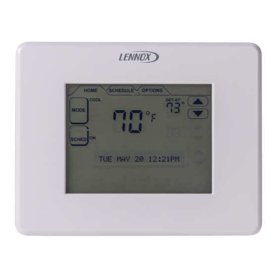
Page 3: Touch Screen Display
Touch Screen Display D Displays room temperature. E Displays the current operation SET AT point(s). If MODE is set to AUTO (autochangeover), both HEAT and COOL set- points are displayed. F Up/down arrows used for adjusting temperature up or down; if in AUTO (autochangeover) mode, two sets of up/down ar- rows appear. -
Page 4: Controlling The Heat/Cool Modes Of Operation
Controlling Heat/Cool Modes of Operation On initial power up or after an a power loss the outdoor sensor is connected and is turned on in user over 2 hours, the thermostat powers up at settings, outdoor temperature will be included in the dis- the HOME screen in the AUTO position. -
Page 5: Controlling The Fan Operation
Controlling the Fan Operation Fan Modes In the CIRC mode, the user can cycle the fan for a programmed percentage of active time per hour, during If backlight is not on continuous, press the periods of equipment inactivity (i.e., heating or cooling screen anywhere to turn on the backlight. -
Page 6: Schedule Tab Programming
Schedule Tab Programming If backlight is not on continuous, press the screen Programming may be performed in groups of days or indi- anywhere to turn on the backlight. Press the SCHEDULE vidual days, as follows: tab along the top of the screen. The display changes to pro- A MON TO SUN −... - Page 7 Schedule Tab Programming (continued) Days & Events Programming process Press NEXT for the next Days change to match group or the next day selected group, e.g. SAT SUN Action Display shows... 10 Repeat steps 3 through 8 for the remaining days, if Press SCHEDULE tab SCHEDULE screen necessary.
-
Page 8: Options Tab Reminders & User Settings
Options Tab Reminders/User Settings CLEAN button [ DATE/TIME Set month, day, year, hour, and minute us- OPTIONS TAB > [CLEAN] ing DATE/TIME option. Select DATE/TIME; press EN- When you select the OPTIONS tab, two buttons appear TER. Small, filled up-arrow is the selected column; use up/ near the bottom of the screen labeled CLEAN and ENTER. - Page 9 Options Tab User Settings (continued) ® FAN CIRCULATE As an option to running the fan all the NOTE − Humiditrol does not function if the outdoor tem- time, fan circulate allows the user to decide how much the perature is 95ºF or greater nor when the indoor tempera- fan will run during periods of equipment inactivity.
-
Page 10: Options Tab Installer Settings
Options Tab Installer Settings Installer Settings For NON HEAT PUMP, use arrows to select backup heat: NO HEAT, GAS/OIL, or ELECTRIC; then press SAVE. OPTIONS TAB > INSTALLER SETTINGS > [ENTER] [ENTER] NON HEAT PUMP NO HEAT COMPRESSOR PROTECT ......Page 13 GAS/OIL CONTACT INFORMATION... - Page 11 Options Tab Installer Settings (continued) SMOOTH SET BACK (SSR) default is OFF. When en- NOTE − Smooth Set Back and STG2 Lock Out operations abled, smooth set back begins recovery up to 2 hours be- vary depending on equipment (see table 2). fore the programmed time so that the programmed tem- SSR STG2 LOCK OUT [not available if SMOOTH SET perature is reached at the corresponding programmed...
-
Page 12: Resetting Program To Factory Conditions
Options Tab Installer Settings (continued) HUMIDITY SETTING See separate sections − Humidifi- A cursor will appear on the second line. Use the arrows to cation (Page 14) and Dehumidification (Page 15). scroll through letters, numbers and special characters. When the desired character appears, press NEXT to ad- STAGE DELAY AND DIFFERENTIAL SETTINGS The vance to the right by one character. -
Page 13: System Test Modes
Options Tab Installer Settings (continued) TEMPERATURE OFFSET default is 0°F. This setting SCROLL arrows move through a list of all signals, Y1 ON, can be used to offset the displayed space temperature by Y1 OFF, Y2 ON, Y2 OFF, etc. With a signal displayed, up to +/−... -
Page 14: Humidification
Humidification INSTALLER SETTINGS Press the box below HUMIDIFY. Use up/down arrows to select DEWPOINT; press ENTER. Humidification (adding moisture to air) is provided only when the thermostat is in heat mode. The humidification HUM MODE SETTING DEF(OFF) DEWPOINT signal (H terminal) to the humidifier (off when the thermo- stat is in the COOL mode) controls humidification. -
Page 15: Dehumidification
Dehumidification INSTALLER SETTINGS Scroll to HUMIDITY SETTINGS; press ENTER. Press the box below DEHUMIDIFY. Dehumidification (removing moisture from air) can occur only when the thermostat is in cool mode. When a dehu- HUMIDITY MODE HUMIDIFY DEHUMIDIFY midification demand is present, a dehumidification signal (0VAC −... -
Page 16: Humiditrol ® Enhanced Dehumidification Accy
Dehumidification (continued) ® Humiditrol Enhanced Dehumidification Acces- Heating only Thermostat will cycle heating ON" and OFF to maintain heating setpoint. Dehumidification func- sory tions are disabled. ® If a Humiditrol EDA is present in the equipment at hand, ® then the ComfortSense Model L7742U thermostat must Autochangeover Dehumidification will only occur if a... -
Page 17: Stage Delay And Differential Settings
Stage Delay & Differential Settings (Installer settings) Press OPTIONS tab for the main options screen, then use Scroll to STG 2 DIFF (or 3 or 4); press ENTER. Select the the arrows to select INSTALLER SETTINGS. Press EN- desired differential. Press SAVE. TER. - Page 18 Stage Delay & Differential Settings (Installer settings) (continued) 1st stage 1st stage Stages Stg1 Differential Locked = 2nd stage 2nd stage Stg2 Differential 1st stage 1st stage Stages Stg1 Differential Locked = 2nd stage 2nd stage Stg2 Differential SET- SP −1.5 SP −1.0 SP −0.5 SP +0.5...
- Page 19 Stage Delay & Differential Settings (Installer settings) (continued) 1st stage 1st stage Stages Stg1 Differential Locked = 2nd stage 2nd stage Stg2 Differential 3rd stage 3rd stage Stg3 Differential 1st stage 1st stage Stages Stg1 Differential Locked = 2nd stage 2nd stage Stg2 Differential 3rd stage...
-
Page 20: Temporary Temperature Change
The information display field continues to display the active Temporary Temperature Change mode, outdoor temperature, indoor relative humidity. Turning the schedule back ON (press SCHED box on home screen) will cancel a permanent hold and return to Two types of temperature changes may be made: tempo- the event-programmed mode. -
Page 21: Service Reminders
Service Reminders Unit Part (Catalog) & Serial Numbers The user may turn on and turn off the following service re- A label on the back of the thermostat is visible through an minders (all of which default to OFF) in either chronological opening in the back of baseplate. -
Page 22: Appendix A. Flow Diagrams & Wiring Diagrams
Appendix A. Flow Diagrams and Wiring Diagrams START HUMIDITROL RUN EQUIPMENT IN there a cooling NORMAL COOLING Is indoor demand MODE temperature > 2ºF above heating set point RUN EQUIPMENT IN NORMAL HEATING there a heating demand MODE indoor temp. greater than the heat Humiditrol Comfort setpoint plus the cool... - Page 23 Appendix A. Flow Diagrams and Wiring Diagrams (continued) Wiring Diagrams Thermostat wiring connections with various units, including dual fuel, zone control, and applications that include the Humidi- ® trol Enhanced Dehumidification Accessory (EDA). See figures 18, 20 and 21. For whole home dehumidifier, refer to the installation instruction for the dehumidifier.
- Page 24 Appendix A. Flow Diagrams and Wiring Diagrams (continued) Figure 21. Thermostat Wiring Diagrams 506230−01 05/09 Page 24...
-
Page 25: Appendix B. Diagnostic Info./Available Sys. Settings
Appendix B. Diagnostic Information and Hidden Menu Tables Diagnostic Information Table Display Text Action to Clear / (Screen2) Recovery Condition Condition Display Text (Screen1) System Action AC power loss for Lithium Battery will remember When AC power is restored, more than 250ms (1/4 the clock for 30 days. - Page 26 Display Text Action to Clear / (Screen2) Recovery Condition Condition Display Text (Screen1) System Action Humiditrol and Dew NO OUTDOOR SENSOR The display of Outdoor sensor If the outdoor sensor reads a point disable and Out- REMIND CLEAR SER- REMIND/CLEAR/ from HOME will be turned value within its normal range.
- Page 27 Display Text Action to Clear / (Screen2) Recovery Condition Condition Display Text (Screen1) System Action Initial Power Up OR SET DATE/TIME Message is displayed on the User has to set the current recovery from power Default DATE/TIME (MON dot Part. date/time to get rid of this mes- loss of more than the JAN 1 12:00 PM)
- Page 28 Available System Settings Setup HEAT PUMP Configurations NON HEAT PUMP Configurations Backup/ In- Gas/Oil Gas/Oil None Gas/Oil Gas/Oil None Elec Elec None Elec Elec None G/O or G/O or None G/O or G/O or None door Heat Elec Elec Elec Elec Comp.