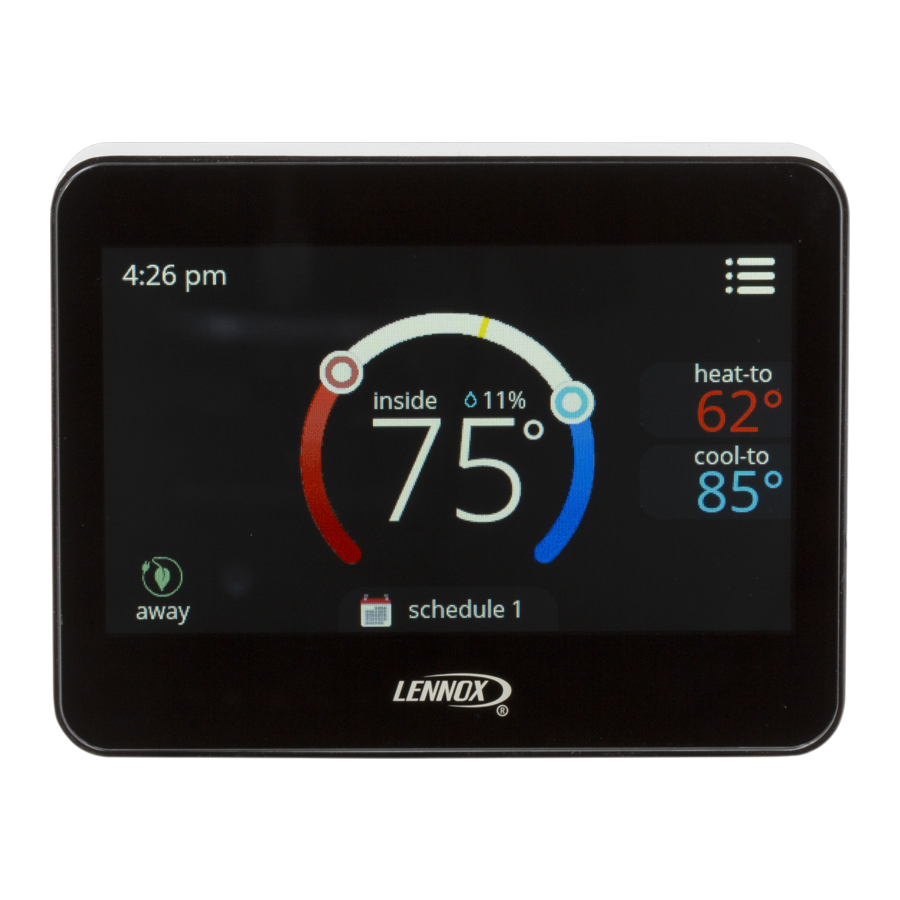
Lennox ComfortSense 7500 Installation And Setup Manual
Color touchscreen programmable thermostat
Hide thumbs
Also See for ComfortSense 7500:
- Installation and setup manual (53 pages) ,
- User manual (24 pages) ,
- Installation and setup manual (36 pages)

Related Manuals for Lennox ComfortSense 7500


Summary of Contents for Lennox ComfortSense 7500
- Page 1 Installation and Setup Guide Color Touchscreen Programmable Thermostat ® ComfortSense 7500 Model: 13H14 507504-02 5/2017 Supersedes 507504-01...
-
Page 2: Table Of Contents
IMPORTANT WARNING Read this manual before programming the ther This product contains a chemical known to the mostat. State of California to cause cancer, birth Use this thermostat only as described in this man defects, or other reproductive harm. ual. Shipping and Packing List ®... -
Page 3: Overview
Dimensions (H x W x D) Overview Case dimensions: 3-5/16 x 4-5/16 x 7/8 in. (84 x 110 x 22mm) Description Wall Plate Dimensions (H x W) ® The ComfortSense 7500 thermostat is an Plate dimensions: 4-1/2” x 5-3/4” (114 x 146mm) electronic 7-day universal... - Page 4 outdoor temperature display on the home screen, balance points, dew point humidity control, and IMPORTANT ® with Humiditrol EDA. ® In all applications, the ComfortSense Model In addition to measuring and displaying outdoor 7500 thermostat can only be used with all temperature, the outdoor sensor provides dew residential units and approved commercial point adjustment and control for all models.
-
Page 5: Installation
accessories being installed. This thermostat is a 24VAC low-voltage thermostat and requires a CAUTION common wire to the thermostat to operate. This is a 24VAC low-voltage thermostat. Do not S Shut off all power to system before installing. install on voltages higher than 30VAC. S Read this entire document, noting which Do not short (jumper) across terminals on the instructions pertain to your equipment and... - Page 6 S Exceed thermostat wire run length greater Not in an enclose environment unless than 300 feet (91m). a remote indoor sensor is used. INSTALLING THERMOSTAT Hot or cold air from ducts. 1. Unpacked the thermostat and open the case Radiant heat from sun or appliances. with a thin-blade screwdriver.
- Page 7 4. Use steps A through J (step J applicable when using provided wall plate) to install the PULL ABOUT 3” OF THERMOSTAT thermostat. WIRE THROUGH OPENING AND RE MOVE OUTER THERMOSTAT WIRE JACKET. CUT OR DRILL A SMALL HOLE THIS WILL HELP IN FOR THERMOSTAT WIRING ROUTING THE THER...
- Page 8 TRIM 1/4” INSULATION FROM END OF EACH WIRE (USE A LEVEL) ALIGN WALL PLATE 1/4” DRILL 3/16” HOLES AT MARKED LOCATIONS ON WALL FOR ANCHORS USE UNIT WALL PLATE AS TEMPLATE TO MARK DESIRED MOUNTING HOLE LOCATIONS ON WALL. NOTE: INSTALLATION OF WALL PLATE IS OPTIONAL.
- Page 9 Thermostat Installation with Wall Plate F - Place wall plate H - Attach back plate J - Attach thermostat to over holes in wall. to wall plate. back plate. G - Insert wall anchors I - Insert provided screws through back and wall through wall plate into wall.
- Page 10 WIRING THERMOSTAT TERMINAL DESIGNATIONS Thermostat wiring connections with various units, Tc - Outdoor Temp. Sensor Connection 1 including dual fuel, zone control, and applications To - Outdoor Temp. Sensor Connection 2 ® that include Humiditrol Enhanced Humidification relay (to Humidifier) Dehumidification Accessory (EDA).
- Page 11 Installing and Displaying Outdoor 4. From the installer settings menu, select Temperature on Home Screen outdoor sensor and select yes. A green check mark will appear next to the selection Install the optional (purchase separately) outdoor that confirms selection. sensor (X2658) on a northern wall of the home, away from direct sunlight or other heat sources 5.
- Page 12 Figure 3. Enhanced Dehumidification Accessory Typical Wiring Diagram...
- Page 13 Figure 4. CBX32MV-XXX-230-06 or Higher and CBX40UHV Wiring Diagrams (Condensing Unit Applications)
- Page 14 Figure 5. CBX32MV-XXX-230-06 or Higher and CBX40UHV Wiring Diagrams (Heat Pump Unit Applications)
- Page 15 WHEN 2-STAGE HEAT IS USED, THERMOSTAT IS CBX25UH AND CBX25UHV DO NOT HAVE TERMINAL CONFIGURED FOR MULIT-STAGE HEAT, CONNECT STRIPS IN UNIT. THERMOSTAT W2 TO AIR HANDLER W2 AND REMOVE JUMPER BETWEEN R AND W2. FOR HUMIDIFIER, 48G95 OR EQUIVALENT ISOLATION RELAY REQUIRED - 24VAC, 5VA MAX CAN BE USED WITH ALL THERMOSTAT CUT ON-BOARD LINK FORM DS-TO-R (W914...
- Page 16 CB30 and CBX32M ML180, ML193, ML195, EL180E, TSTA EL195E, ELO183, SLO185 TSTA ML180, ML193, ML195, EL180E, EL195E, ELO183, SLO185 TSTAT Figure 7. Thermostat Wiring Diagrams (continued)
- Page 17 CBX25UH, CBX25UHV, CBX32MV ML180, ML193, ML195, TSTAT EL180E, EL195E, ELO183, SLO185 TSTAT Figure 8. Thermostat Wiring Diagrams (continued)
- Page 18 EL280P TSTAT EL296E, EL296V, SL280V TSTAT Figure 9. Thermostat Wiring Diagrams (continued)
- Page 19 CBX25UH, CBX25UH, CBX25UHV, CBX25UHV, TSTAT CBX32MV CBX27UH TSTAT Figure 10. Thermostat Wiring Diagrams (continued)
- Page 20 ML180, ML193, ML195, EL296E, SL280V, EL180E, EL195E, EL296V, SLP98 TSTAT ELO183, SLO185 TSTAT Figure 11. Thermostat Wiring Diagrams (continued)
-
Page 21: System Settings
MENU System Settings 1. Touch menu option from the home screen. 2. Touch and hold the settings option on the menu menu. This will display the installer settings notice and then menu. You may be asked for an access code. The factory default access notifications code is 864. - Page 22 SYSTEM SETUP Balance Point, then heat pump heating is not allowed and only backup heat will be used. Sets the thermostat for operation with either a non-heat pump or heat pump and defines the 2. When in heat mode and the outdoor number of compressor stages.
- Page 23 DEADBAND SSR STAGE 2 LOCK OUT Default is 20 minutes. Use the + or - option to set Default is 2°F. The deadband setting is the the number of minutes before the programmed minimum difference between the cooling and event time that stage 2 is allowed to operate (20 to heating set points.
- Page 24 Table 1. Smooth Set Recovery (SSR) & SSR Stg 2 Lock Out Operation When SSR is enabled then SSR Stage 2 lock out is enabled. Can When SSR is disabled then SSR Stg 2 Equipment Available be set between 20 and 120 lock-out setting is disabled.
- Page 25 When SSR is enabled then SSR When SSR is disabled then SSR Stg 2 Equipment Available Stg 2 lock out is automatically lock-out setting is disabled. enabled. S Run heat pump (Y1) until a second- stage heating demand is needed S Run heat pump (Y1) only Single-stage heat pump which is determined by the time /...
- Page 26 When SSR is enabled then SSR When SSR is disabled then SSR Stg 2 Equipment Available Stg 2 lock out is automatically lock-out setting is disabled. enabled. S Run HP (Y1/Y2) until a second-stage S Run heat pump (Y1/Y2). Two-stage heat pump demand is needed which is deter...
- Page 27 STAGE DELAY TIMER STAGE 2 THROUGH 4 DIFF Default is ON. When ON, all stage delay timers (Where applicable) The default is 1.0°F but can be (stages 2, 3, and 4) are enabled and will serve to programmed between 0.5° and 8.0°F in 0.5°F bring on additional stage(s) of cooling or heating increments.
- Page 28 STAGE 2 HP LOCK TEMP outdoor temperature is at or less than the LOCK TEMP set point. Scroll to STAGE 2 HP LOCK Default is off (heat pump stage 2 operates TEMP; touch ENTER. Use - + option to select a normally).
- Page 29 1st stage 1st stage Stages Stg1 Differential Locked = 2nd stage 2nd stage Stg2 Differential 1st stage 1st stage Stages Stg1 Differential Locked = 2nd stage 2nd stage Stg2 Differential SET SP -1.5 SP -1.0 SP -0.5 SP +0.5 SP +1.0 SP +1.5 SP +2.0 POINTS:...
- Page 30 1st stage 1st stage Stages Stg1 Differential Locked = 2nd stage 2nd stage Stg2 Differential 3rd stage 3rd stage Stg3 Differential 1st stage 1st stage Stages Stg1 Differential Locked = 2nd stage 2nd stage Stg2 Differential 3rd stage 3rd stage Stg3 Differential SET...
- Page 31 1st stage 1st stage Stages Stg1 Differential Locked = 2nd stage 2nd stage Stg2 Differential 3rd stage 3rd stage Stg3 Differential 4th stage 4th stage Stg4 Differential 1st stage 1st stage Stages Stg1 Differential Locked = 2nd stage 2nd stage Stg2 Differential 3rd stage 3rd stage...
- Page 32 1st stage 1st stage Stages Stg1 Differential Locked = 2nd stage 2nd stage NO or Stg2 Differential SET SP -3.0 SP -2.5 SP -2.0 SP -1.5 SP -1.0 SP -0.5 SP +0.5 POINTS: Figure 18. Heating - dual fuel - 2 stage (1 compressor / 1 backup) 1st stage 1st stage Stages...
- Page 33 1st stage 1st stage Stages Stg1 Differential Locked = 2nd stage 2nd stage Stg2 Differential 3rd stage 3rd stage Stg3 Differential 1st stage 1st stage Stages Stg1 Differential Locked = 2nd stage 2nd stage Stg2 Differential 3rd stage 3rd stage Stg3 Differential SET...
- Page 34 1st stage 1st stage Stages Stg1 Differential Locked = 2nd stage 2nd stage Stg2 Differential 3rd stage 3rd stage Stg3 Differential 4th stage 4th stage Stg4 Differential 1st stage 1st stage Stages Stg1 Differential Locked = 2nd stage 2nd stage Stg2 Differential 3rd stage 3rd stage...
- Page 35 COMPRESSOR PROTECT screen will appear and a list all of the predefined reminders plus the two custom reminders will Default is ON and it can be turned OFF, however appear at the end of the list. only for one compressor cycle and then it will revert back to ON.
- Page 36 Table 2. Energy Saving Set Points Time Heating Cooling Wake 70°F (21°C) 78°F (25°C) NOTE - Humidification and dehumidifica tion are not part of the energy savings pro Leave 62°F (17°C) 85°F (29°C) gram. A higher utility bill may occur when not using the setpoints in this table.
-
Page 37: Humidify
system test mode NOTICE Risk of equipment damage. Can cause compressor failure. In dual fuel system applications, do not turn on heat pump and furnace at the same time in sys tem test mode. All HVAC components can be tested to confirm the signals between thermostat and unit are being sent and were received. - Page 38 humidification signal (H terminal) to the humidifier must be enabled before the user will have control (off when the thermostat is in the COOL mode) over the humidity. The humidity mode selected controls humidification. When the thermostat is determines how the user can adjust the relative powered, the H terminal is normally inactive (open humidity (RH).
-
Page 39: Dehumidify
Outdoor Temp (ºF) user dew point + 25 adjustment set point cannot exceed +/-15% and Where: user dew point adjustment minimum is 15% and cannot exceed 45%. setpoint DEW POINT NORMAL & MAX the speed the indoor blower during dehumidification. At the same time, the Y1 and Y2 Dew point adjustment mode will change the (if available) terminals become activated with humidification set point based on the outdoor... - Page 40 S Humiditrol: Runs based on humidity reading 5. OFF from thermostat's internal humidity sensor, NORMAL heating set point and outside temperature. In this mode, dehumidification occurs if these Will over cool space based on settings of min conditions are met and signals are present at NOTE - The D terminal is ALWAYS activated specific terminals: (24VAC) when the thermostat is in HEAT or OFF...
- Page 41 ® AUXILIARY DEHUMIDIFIER If a Humiditrol EDA is installed and enabled, then the thermostat must be configured to properly The auxiliary dehumidifier setting is used when a ® operate the Humiditrol EDA as follows (see whole home dehumidifier used ® Figure 22 for the Humiditrol EDA operation dehumidification.
-
Page 42: Unit Part (Catalog) & Serial Numbers
If the humidification sensor fault occurs, then the H A label on the back of the thermostat is visible terminal becomes inactive, and the D terminal through an opening in the back of base plate. This goes to 24VAC. identifies the Lennox Catalog Number, Part... -
Page 43: Memory Protection
Number and Serial Number. Separate the base in the home. Day and time (schedules) may be off plate from the thermostat to see additional due to battery loss. manufacturing information. User Settings Memory Protection Please refer to the user guide for information on The thermostat stores all the information the following: concerning its programming (state, mode,... - Page 44 START HUMIDITROL RUN EQUIPMENT there a cooling IN NORMAL COOL Is indoor demand ING MODE temperature > 2ºF above heating set point RUN EQUIPMENT there a heating IN NORMAL HEAT demand ING MODE Humiditrol Com indoor temp. greater than the heat fort Adjust setting setpoint plus the cool setpoint divided by 2?
- Page 45 Table 3. Diagnostic Information Priority Error Screen 0:high Message Action to Clear / Condition System Action 1:middle Code Text Type Recovery Condition 2:low High tempera All stages of heat are turned Once temperature ture protection high tem off by safety relay. drops below 96°F when outdoor perature...
- Page 46 Priority 0:high Error Screen Message Action to Clear / Condition System Action 1:middle Code Text Type Recovery Condition 2:low System will restore using to Energy Star defaults and re memory EEPROM error Thermostat will need sume operations. critical error (Power ON) to be replace.
- Page 47 Priority 0:high Error Screen Message Action to Clear / Condition System Action 1:middle Code Text Type Recovery Condition 2:low For Outdoor Temperature Sen sor: No Humiditrol or Humidity op eration. D terminal stays acti vated and other operation will continue to operate. Thermostat will stop the sys...
- Page 48 Priority 0:high Error Screen Message Action to Clear / Condition System Action 1:middle Code Text Type Recovery Condition 2:low With humidifier or dehumidifier) and conditions are as follows: All humidity operation will 0%: Stat will stop and the reading for hu detect error midity will not be valid.
- Page 49 Priority 0:high Error Screen Message Action to Clear / Condition System Action 1:middle Code Text Type Recovery Condition 2:low will resume The reading for humidity will operation. not be valid. Without humidifi This message indicates hum er or dehumidifi sensor is not working cor humidity er and the sen...
- Page 50 Table 4. Reminder Information Error Message Screen Text Action to Clear / Recovery Condition Code Type replace media filter replace UV lamp replace humidity pad routine system check-up reminder Touch either done to clear the reminder or remind later button. replace metal insert for pure air user editable user editable...
- Page 51 Table 5. Supported Configurations This thermostat support air conditioner and heat pump systems with one or two speed compressors. It also supports dual-fuel and Humiditrol accessory. For all possible configuration see table below. Backup/ Backup/ 1st Em Indoor Comp. Heat 4th Heat 2nd Em Cool...
- Page 52 Backup/ Backup/ 1st Em Comp. Heat 4th Heat 2nd Em Cool Indoor Indoor Heat Heat Heat Cool Cool 3rd Heat Stg stgs heat Stg Stgs Heat Heat Stg GAS/OIL W1+W2 ELEC. NONE GAS/OIL Y1+Y2 ELEC. GAS/OIL W1+W2 Y1+Y2 ELEC. NONE Y1+Y2...
- Page 53 Table 6. Installation Checklist Item Item Number Is the thermostat level where mounted on the wall? Is the thermostat installed away from direct sunlight or dis charge air vents? Has the thermostat been wired correctly based on the type of equipment installed (air handler, outdoor unit and accessories? Is the thermostat wiring secured tightly to the terminals? Is the common wire (terminal C) connected?
- Page 54 INDEX Normal, 40 Diagnostic Information, 45 Dimensions Thermostat, 3 Access Code, 21 Wall Plate, 3 Balance Points, Low, High, 22 Edit Schedules, 43 Energy Saving Defaults, 36 Code, 21 Enhanced Dehumidification Accessory, 12 Compressor Short Cycle Protection, 3 Custom Reminder, 35 Fan Operation, 43 Humidification Sensor Fault, 42 Date and Time, 43...
- Page 55 Installer code, 21 Reminders, 43 Reset Settings, 35 Installer Settings, 21 Residual Cool, 22 Language Selection, 43 Screen Brightness, 43 Limits (Heating and Cooling), 43 Screen Lock, 43 Screen Savers, 43 Memory Protection, 43 Screws, 2 Menu Screen, 21 Smooth Set Back (SSR), 23 Mode of Operations, 43 Smooth Set Back Stage 2 Lock Out, 23 Stage 1 Differential, 27...
- Page 56 Terminal Designations, 10 Thermostat Installation, 6 Wall Anchors, 2 Wiring Diagrams, 12, 13, 14, 15, 16, 17, 18, 19, Unit Part (Catalog) & Serial Numbers, 42 User Settings, 43 Wiring Thermostat, 10...