
Related Manuals for Acer Aspire M7720


Summary of Contents for Acer Aspire M7720
- Page 1 Aspire ASM7720 Service Guide Service guide files and updates are available on the AIPG/CSD web; for more information please refer to http://csd.acer.com.tw PRINTED IN TAIWAN...
-
Page 2: Revision History
Revision History Please refer to the table below for the updates made on aBulldog ASM7720 Service Guide. Date Chapter Updates... - Page 3 Copyright Copyright © 2007 by Acer Incorporated. All rights reserved. No part of this publication may be reproduced, transmitted, transcribed, stored in a retrieval system, or translated into any language or computer language, in any form or by any means, electronic, mechanical,...
- Page 4 Conventions The following conventions are used in this manual: SCREEN Denotes actual messages that appear on screen. MESSAGES NOTE Gives bits and pieces of additional information related to the current topic. WARNING Alerts you to any damage that might result from doing or not doing specific actions.
- Page 5 ACER-AUTHORIZED SERVICE PROVIDERS, your Acer office may have a DIFFERENT part number code to those given in the FRU list of this printed Service Guide. You MUST use the list provided by your regional Acer office to order FRU parts for repair and service of customer machines.
-
Page 6: Table Of Contents
Chapter 1 System Specifications 1 F e a t u r e s … … … … … … … … … … … … … … … … … … … … … … … … … … … … … … … … … … … . . . 1 B l o c k D i a g r a m …... -
Page 7: Chapter 1 System Specifications
System Specifications Features Operating System Microsoft Windows Vista Processor Socket Type: Intel® Socket T LGA 1366 pin Processor Type: Intel Bloomfield i7 CPUs FSB 1600 MHz CPUs Chipset Intel X58 + ICH10R Form Factor: Micro ATX Dimension/Layer: 244mm x244mm Memory Memory Type: DDR3 1066 Support single channel 64 bit mode with maximum memory size up to 12GB Support un-buffered DIMM (ICH10R) - Page 8 PCI Express x1 Slot Quantity: 1 SATA Slot Type: SATA slot Slot Quantity: 6 Storage Type support: HDD/CD-ROM/CD-RW/DVD-ROM/DVD-RW/DVD+RW/DVD Dual/DVD SuperMultiPlus/Blu-Ray ODD Audio Audio Type: HD audio codec Audio Channel: 7.1 channel Audio Controller /Codec: ALC888S-VE 7.1 Connectors support: Rear 6 jack follow HD audio definition, Audio jacks color coding: should meet Microsoft Windows Logo Program Device Requirements: Audio-0002 1 front panel audio header (2*5)
- Page 9 Connector Quantity: 2 1 rear 6pin IEEE1394 port 1 2x5pin onboard jumper BIOS BIOS Type: Phoenix Award or AMI Kernel with Acer skin Size: 32Mb Note: Boot ROM should be included (PXE function should be built in with default and RPL function is optional by service BIOS)
-
Page 10: Power Supply
Chasses accepts PS2, PS3 style power supply Features for internal mounting tab Location of 4 external mounting holes Power Supply Electrical Design Feature 400W ~1000W in stable mode (Acer Assign System Power Unit) Voltage design should be covered +5V, +3.3V, +12V, +5VSB, -12V (attention to... - Page 11 12V output capability) Demand for both PFC/Non-PFC solutions (two different quotations are needed) Minimum 6 Serial ATA power connector solution should be included (by default) Minimum 3 6-pin graphic card connector included Minimum 2 big 4-pin power connector included Full Range PSU PS2 style...
-
Page 12: Block Diagram
Block Diagram... -
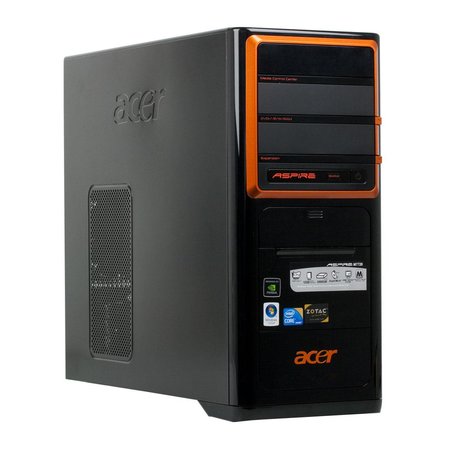
Page 13: Aspire Asm7720 Front Panel
Aspire ASM7720 Front Panel The computer’s front panel consists of the following: Label Media Control Center Optical drive Speaker /Microphone jack Gateway Logo Card reader Power button Description... - Page 14 Aspire M5700 Rear Panel Label Description Voltage selector switch Power card socket PS/2 keyboard connecter Serial port ESATA port USB 2.0 connector Audio connector Label Description Fan aperture PS/2 mouse connecter System FAN 1394 connector LAN connector Lock Handle...
-
Page 15: Hardware Specifications And Configurations
Intel Bloomfield i7 CPUs LGA 1366 pin 1600 MHz 0 MHz (If Stop CPU Clock in Sleep State in BIOS Setup is set to Enabled.) Specification Phoenix Award or AMI Kernel with Acer skin R01-A1 SPI Flash 32Mb SMBIOS(DMI)2.4/DMI2.0 1st priority: SATA HDD... -
Page 16: Bios Hotkey List
BIOS Hotkey List Hotkey Function Enter BIOS Setup Utility Main Board Major Chips Item North Bridge Intel X58 South Bridge ICH 10R APG controller Intel X58 Super I/O controller ITE 8720 Audio controller Realtek HD audio codec ALC888S-VE codec 7.1 (co-lay with ALC888) LAN controller Intel 82567LF Boazman Gbe Ethernet LAN PHY... -
Page 17: Memory Combinations
Memory Combinations Slot Memory Slot 1 1GB, 2GB Slot 2 1GB, 2GB Slot 3 1GB, 2GB Slot 4 1GB, 2GB Slot 5 1GB, 2GB Slot 6 1GB, 2GB Maximum System Memory Supported System Memory Item Memory slot number Support Memory size per socket Support memory type Support memory interface Support memory voltage... -
Page 18: Audio Interface
Audio Interface Item Audio controller Audio controller type Audio channel Audio function control Mono or stereo Compatibility Music synthesizer Sampling rate MPU-401 UART support Microphone jack Headphone jack Specification Intel ICH 10R ALC888S-VE codec 7.1 Enable/disable by BIOS Setup Stereo Sound Blaster Pro/16 compatible Mixed digital and analog high performance chip Enhanced stereo... -
Page 19: Sata Interface
SATA Interface Item SATA controller SATA controller resident bus Number of SATA channel Support bootable CD-ROM USB Port Item Universal HCI USB Class USB Connectors Quantity Specification Intel ICH 10R PCI bus SATA X 6 Specification USB 2.0/1.1 Support legacy keyboard for legacy mode 6 back panel ports 4 ports for front daughter board... -
Page 20: Environmental Requirements
Environmental Requirements Item Temperature Operating Non-operating Humidity Operating Non-operating Vibration Operating (unpacked) Specification +5°C ~ +35°C -20 ~ +60°C (Storage package) 15% to 80% RH 10% to 90% RH 5 ~ 500 Hz: 2.20g RMS random, 10 minutes per axis in all 3 axes 5 ~500 Hz: 1.09g RMS random, 1 hour per axis in all 3 axes... -
Page 21: Power Management
Power Management Devices Power Button Keyboard/Mouse Devices wake up from S3 should be less than Devices wake up from S5 should be less than 10 seconds Disabled Disabled Disabled Disabled Disabled Disabled Disabled Disabled Disabled Disabled Disabled Disabled... -
Page 23: Chapter 2 System Utilities
Chapter 2 System Utilities The manufacturer or the dealer already configures most systems. There is no need to run Setup when starting the computer unless you get a Run Setup message. The Setup program loads configuration values into the battery-backed nonvolatile memory called CMOS RAM. -
Page 24: E N T E R I N G S E T U
Entering Setup Power on the computer and the system will start POST (Power On Self Test) process. When the message of “Press DEL to enter SETUP” enter the setup menu. NOTE: If the message disappears before you respond and you still wish to enter Setup, restart the system by turning it OFF and On. - Page 25 The items in the main menu are explained below: Parameter Production Information Standard CMOS Features Advance BIOS Features Advance Chipset Features Integrated Peripherals Power Management Setup PC Health Status Frequency/Voltage Control BIOS Security Features Load Optimized Defaults Save & Exit Setup Exit Without Saving Description This page shows the relevant information of the main...
-
Page 26: P R O D U C T I N F O R M A T I O
Product Name Product Name System Serial Number System BIOS Version BIOS Release Date Product Information : 2.66GHz : 4047MB : Acer : Asprie M7720 : R01-A1 : 10/28/2008 +/-/: Value F9: Optimized Defaults Description This item lists the product processor model... -
Page 27: Standard Cmos Setup
Standard CMOS Setup Select standard CMOS features from the main menu to configure some basic parameters in your system the following screen shows the standard CMOS features menu: CMOS Setup Utiliyt – Copyright (c) 1985-2005,American Megatrends, Inc. System Time System Date 8AHCI Port0 8AHCI Port1 8AHCI Port2... - Page 28 The following table describes the parameters found in this menu. Parameter System Date To set the date following weekday-month-date-year format System Time To set the time following the hour-minute-second format Halt On This item enables use to select the situation if the BIOS stops the POST process and the notification...
-
Page 29: A D V A N C E D B I O S F E A T U R E
Advanced Setup The following screen shows the Advanced Setup: CMOS Setup Utiliyt – Copyright (c) 1985-2008,American Megatrends, Inc. Reset Configuration Data Quick Boot Quiet Boot 1 st Boot Device 2 nd Boot Device Hard Disk Drives CD/DVD Devices Boot up Num-Lock USB Beep Message : Move F1: General Help... -
Page 30: Advanced Chipset Setup
Advanced Chipset Setup CMOS Setup Utiliyt – Copyright (c) 1985-2008,American Megatrends, Inc Intel EIST Intel XD Bit Intel VT Intel VT-d : Move Enter: Select F1: General Help The following table describes the parameters found in this menu. Parameter Intel EIST For Intel platform Intel XD Bit For Intel platform... -
Page 31: I N T E G R A T E D P E R I P H E R A L
Integrated Peripherals CMOS Setup Utility – Copyright (c) 1985-2008, American Megatrends, Inc. Onboard SATA Mode Onboard ESATA Controller Onboard USB Controller Legacy USB Support Onboard LAN Controller Onboard LAN Option ROM Onboard Audio Controller Onboard 1394 Controller Serial Port1 Address : Move F1: General Help Integrated Peripherals... - Page 32 The following table describes the parameters found in this menu. Parameter Onboard SATA Mode Onboard ESATA Mode Onboard USB Controller Legacy USB Support Onboard Audio Controller Onboard LAN Controller Onboard LAN Option ROM Serial Port1 Address Description This item is only available when onboard SATA controller is AHCI This item is only available when onboard ESATA controller is AHCI...
-
Page 33: P O W E R M A N A G E M E N
Power Management The Power Management menu lets you configure your system to most effectively save energy while operating in a manner consistent with your own style of computer use. The following screen shows the Power Management parameters and their default settings: CMOS Setup Utiliyt –... -
Page 34: P C H E A L T H S T A T U
PC Health Status CMOS Setup Utiliyt – Copyright (c) 1985-2008,American Megatrends, Inc. CPU Temperature (PECI Mode) System Temperature CPU Fan Speed System Fan Speed CPU Core +1.1V +3.30V +5.00V +12.0V 5VSB VBAT Smart Fan : Move Enter: Select F1: General Help The following table describes the parameters found in this menu: Parameter CPU/System Temperature... -
Page 35: F R E Q U E N C Y / V O L T A G E C O N T R O
Frequency/Voltage Control CMOS Setup Utiliyt – Copyright (c) 1985-2008,American Megatrends, Inc Spread Spectrum : Move Enter: Select F1: General Help The following table describes the parameters found in this menu: Parameter Spread Spectrum Frequency/Voltage Control Enabled Spread spectrum modulation +/-/: Value F10: Save ESC: Exit Optimized Defaults Description... -
Page 36: B I O S S E C U R I T Y F E A T U R E
BIOS Security Features CMOS Setup Utiliyt – Copyright (c) 1985-2008,American Megatrends, Inc. Supervisor Password User Password Change Supervisor Password : Move Enter: Select F1: General Help The following table describes the parameters found in this menu: Parameter Change Supervisor Password BIOS Security Features : Not installed : Not Installed... -
Page 37: L O A D D E F A U L T S E T T I N G
Load Default Settings This option opens a dialog box that lets you install defaults for all appropriate items in the Setup Utility. CMOS Setup Utiliyt – Copyright (c) 1985-2008,American Megatrends, Inc. Product Information Standard CMOS Features Advance BIOS Features Advanced Chipset Features Integrated Peripherals Power Management Setup : Move Enter: Select... -
Page 38: S A V E & E X I T S E T U
Save & Exit Setup Highlight this item and press <Enter> to save the changes that you have made in the Setup Utility and exit the Setup Utility. The following table describes the parameters found in this menu: Parameter Description Save & Exit Setup Press <Enter> to save the changes that have made in the Setup Utility and exit the Setup Utility. -
Page 39: E X I T W I T H O U T S A V I N
Exit Without Saving Highlight this item and press <Enter> to discard any changes that you have made in the Setup Utility and exit the Setup Utility. Parameter Exit Without Saving Description Press<Enter> to discard any changes and exit the Setup Utility Options... -
Page 40: Chapter 3 Machine Disassembly And Replacement
Machine Disassembly and Replacement To disassemble the computer, you need the following tools: Wrist grounding strap and conductive mat for preventing electrostatic discharge. Wire cutter. Phillips screwdriver (may require different size). NOTE: The screws for the different components vary in size. During the disassembly process, group the screws with the corresponding components to avoid mismatches when putting back the components. -
Page 41: G E N E R A L I N F O R M A T I O
General Information Before You Begin Before proceeding with the disassembly procedure, make sure that you do the following: 1. Turn off the power to the system and all peripherals. 2. Unplug the AC adapter and all power and signal cables from the system... -
Page 42: D I S A S S E M B L Y P R O C E D U R
Disassembly Procedure This section tells you how to disassemble the system when you need to perform system service. Please also refer to the disassembly video, if available. CAUTION: Before you proceed, make sure you have turned off the system and all peripherals connected to it. - Page 43 Bulldog ASM7720 Standard Disassembly Process Bezel Process: 1. According to the requirement, paste ATI, OS, CPU, HDMI and marketing label by SKU. Remove side cover Process: 1. Put the Computer on the worktable lightly. 2. Release left/right side cover with 4 screws then remove left/right side cover.
- Page 44 Remove CPU fan pipe Process: 1. Release the CPU fan pipe.
-
Page 45: Remove Cards
Remove Cards Process: 1. Release the slot cover tooless 2. Remove VGA ﹑ TV﹑ Modem Card,the following list is for your reference about the mutual location relation (Optional by SKU). -
Page 46: Remove Hdd Data Cables
Remove HDD Data Cables Process: 1. Remove master HDD data cable from M/B SATA1/SATA3(Optional by SKU). 2. Remove slave ODD data cable from M/B SATA2/SATA4(Optional by SKU) -
Page 47: Remove Odd Data Cable
Remove master HDD cable Remove slave HDD cable Remove ODD DATA cable Process: 1. Remove master ODD data/power cable from Master ODD. -
Page 48: Remove Cables
Remove HDD power cable Process: 1. Remove master HDD data cable from master HDD. 2. Remove slave HDD data cable from slave HDD. Remove Cables Process: 1. Remove Power SW cable cable from M/B. 2. Remove FI/O USB cable from M/B. 3. -
Page 49: Remove Hdd
Remove HDD Process: 1. Remove the screws and take out HDD bracket . 2. Remove two sides with 2 screws for each and then remove the master HDD and Slave HDD. 3. Remove Slave HDD from the second HDD location. (Optional by SKU) -
Page 50: Remove Odd
Master HDD location Slave HDD location Process: 1. Remove bezel of chassis. 2. Remove Master ODD from the location. 3. Remove slave ODD from the location. (Optional by SKU) Remove ODD... - Page 51 Remove Cables Process: 1. Remove M/B power cable from M/B “ATX1”. 2. Remove 12 V power cable from M/B” JPW1” 3. Remove System Fan cable from M/B”SYS-F2”. M/B power cable...
-
Page 52: Remove System Fan
12V CPU Power cable SYS_FAN port Remove System FAN Process: 1. Release four screws according to the following picture. 2. Remove Sys Release four screws. FAN (Optional by SKU) - Page 53 Remove mother board Process: 1. Release 8 pcs screws form the corresponding hole. 2. Release screws according to the following picture in turn. Remove the Mother board from chassis.
-
Page 54: Remove Cpu Cooler
Remove CPU cooler Process: 1. Remove cooler power cable from M/B “CPU-F2”. 2. Release screw 1 first, then fixes screw 2, screw 3 & screw 4 (As Picture). Remove Cooler from the Retention module. Remove memory Process: 1. Remove the first Memory from DIMM. 2. -
Page 55: Remove Cpu
Process: 1. Remove CPU according following the pictures. Process: 1. Remove I/O Shielding. Remove CPU Lock the Handle Remove I/O shielding... -
Page 57: Chapter 4 Troubleshooting
Troubleshooting Please refer to generic troubleshooting guide for troubleshooting information relating to following topics: Power-On Self-Test (POST) POST Check Points POST Error Messages List Error Symptoms List Chapter 4... - Page 58 Chapter 5...
- Page 60 ATX_POWER: ATX 24-pin Power Connector Signal Name +3.3 +3.3 PWR OK 5VSB +12V +12V +3.3V Signal Name +3.3V -12V PS_ON...
-
Page 63: Chapter 6 Fru (Field Replaceable Unit) List
ACER-AUTHORIZED SERVICE PROVIDERS, your Acer office may have a DIFFERENT part number code to those given in the FRU list of this printed Service Guide. You MUST use the local FRU list provided by your regional Acer office to order FRU parts for repair and service of customer machines. - Page 64 MCI ASSY GEAR-BKT POWER SWITCHWITH CABLE GEAR(PG-08A-45W) BACKUP SWITCH WITH CABLE MCR BOTTOM DOOR-LOCK(DL-400) FIO(2AUDIO+2USB+1394) SCREW(FOR FIO-RACK) DESCRIPTION FIO-RACK FRONT-AXES STANDOFF-A BASE BEZEL FOR ACER RUBBER-FOOT(FRONT) SCREW RUBBER-FOOT(BACK) GLIP CLAMP CHF-B-3M PLT,BK,I/O,EVT 2-PCI-SHIELD 1-BACK CPU CLAMP FW-IDL-NOW LITEON 500W FULL RONGE...