
Related Manuals for Acer Aspire M3710


Summary of Contents for Acer Aspire M3710
- Page 1 Aspire M3710 Aspire M5711 Aspire M7711 Service Guide Service guide files and updates are available on the AIPG/CSD web; for more information please refer to http://csd.acer.com.tw PRINTED IN TAIWAN...
-
Page 2: Revision History
Revision History Please refer to the table below for the updates made on Aspire M3710/Aspire M5711/ Aspire M7711 service guide. Date Chapter Updates... - Page 3 Copyright Copyright © 2008 by Acer Incorporated. All rights reserved. No part of this publication may be reproduced, transmitted, transcribed, stored in a retrieval system, or translated into any language or computer language, in any form or by any means, electronic, mechanical, magnetic, optical, chemical, manual or otherwise, without the prior written permission of Acer Incorporated.
- Page 4 Conventions The following conventions are used in this manual: SCREEN Denotes actual messages that appear on screen. MESSAGES NOTE Gives bits and pieces of additional information related to the current topic. WARNING Alerts you to any damage that might result from doing or not doing specific actions.
- Page 5 PROVIDERS, your Acer office may have a DIFFERENT part number code to those given in the FRU list of this printed Service Guide. You MUST use the list provided by your regional Acer office to order FRU parts for repair and service of customer machines.
-
Page 6: Table Of Contents
Chapter 1 System Specifications 1 Features……………………………………………………………………………………………... 1 Main board Placement…………………………………………………….……..……………..6 Block Diagram…………………………………………………………..………………...………..8 Aspire M3710 Front Panel...……………….……………..…….………..…..……...9 Aspire M3710 Rear Panel………………………………………..…………………..…………………10 Aspire M5711 Front Panel...……………….……………..…….………..…..……...11 Aspire M5711 Rear Panel………………………………………..…………………..…………………12 Aspire M7711 Front Panel...……………….……………..…….………..…..……...13 Aspire M7711 Rear Panel………………………………………..…………………..…………………14 Hardware Specifications and Configurations………………….…….……..15 Power Management Function (ACPI support function)…………………………..…...20... -
Page 7: Chapter 1 System Specifications
Processor Type: Intel Pentium Dual Core / Core 2 Duo / Core2 Quad (up to 95W CPUs FSB 1066/1333 MHz CPUs Chipset NV MCP7A-O (Aspire M3710) / MCP7A-D (Aspire M7711/M5711) Form Factor: Micro ATX Dimension/Layer: 244mm x244mm Memory Memory Type: DDR2 800... - Page 8 PCI Slot Quantity: 2 Slot Quantity: 1 Design Criteria: Should support 1.44MB/3 mode 3.5” Devices SATA Slot Type: SATA slot Slot Quantity: 6 Storage Type support: HDD/CD-ROM/CD-RW/DVD-ROM/DVD-RW/DVD+RW/DVD Dual/DVD SuperMultiPlus/Blu-Ray ODD Audio Audio Type: HD audio codec Audio Channel: 7.1 channel Audio Controller /Codec: ALC888S HD codec 7.1 Connectors support: Rear 6 jack follow HD audio definition, example as below...
- Page 9 Connector Quantity: 2 1 rear 6pin IEEE1394 port 1 2x5pin onboard jumper BIOS BIOS Type: Phoenix Award or AMI Kernel with Acer skin Size: 4Mb Note: Boot ROM should be included (PXE function should be built in with default and RPL function is optional by service BIOS)
- Page 10 1 PS/2 Mouse port, 1 COM port 1 HDMI port (Aspire M3710 series only), 1 D-Sub port, (Aspire M3710 series only) 1 RJ45 LAN port, 1 IEEE 1394 port (6 pin) (Aspire sku only) 4 USB ports 7.1 channel phone jack (6 audio jacks)
-
Page 11: Power Supply
Features for internal mounting tab Location of 4 external mounting holes Power Supply Electrical Design Feature 400W/300W/250W in stable mode (Acer Assign System Power Unit) Design for NVidia MCP7A/B series chipset compatible system Voltage design should be covered +5V, +3.3V, +12V, +5VSB, -12V... - Page 12 PFC version will not provide switch selector for 115/230V AC input but it should be universal for Europe and China Non-PFC version should provide switch selector for 115/230V AC input and universal for worldwide PS2 style...
-
Page 13: Main Board Placement
Main board Placement... -
Page 14: Block Diagram 1
Block Diagram 1... - Page 15 Block Diagram 2...
-
Page 16: Aspire M3710 Front Panel
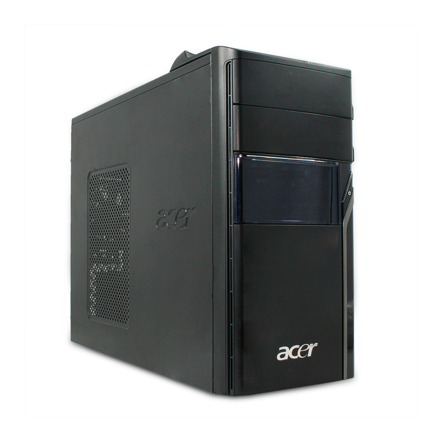
Aspire M3710 Front Panel The computer’s front panel consists of the following: Label USB ports Optical drive Card reader FDD Cover Speaker/Microphone jack Power button Power and HDD LED Acer Logo Description... -
Page 17: Aspire M3710 Rear Panel
Aspire M3710 Rear Panel Label Description Power card socket Voltage selector switch PS/2 keyboard connector HDMI connector Com port USB 2.0 connector Audio connector Label Description Fan aperture PS/2 mouse connector System Fan Monitor connector 1394 connector LAN connector Lock Handle... -
Page 18: Aspire M5711 Front Panel
Aspire M5711 Front Panel Label USB ports Floppy disk drive Acer Logo Optical drive Card reader Power button LED module Speaker/ Microphone jack Description... -
Page 19: Aspire M5711 Rear Panel
Aspire M5711 Rear Panel Label Description Power card socket Voltage selector switch PS/2 keyboard connector USB connector Audio connector Fan aperture PS/2 mouse connector Label Description System Fan 1394 connector LAN connector Lock Handle... -
Page 20: Aspire M7711 Front Panel
Aspire M7711 Front Panel Label Media Control Interface Optical drive Acer Logo Power button Description... -
Page 21: Aspire M7711 Rear Panel
Aspire M7711 Rear Panel Label Power card socket PS/2 keyboard connector USB 2.0 connector Audio connector Fan aperture Description Label Description PS/2 mouse connector System Fan 1394 connector LAN connector... -
Page 22: Hardware Specifications And Configurations
CPUs) LGA 775 pin 1066/1333 MHz CPUs 0 MHz (If Stop CPU Clock in Sleep State in BIOS Setup is set to Enabled.) Phoenix Award or AMI Kernel with Acer skin V6.0 SPI Flash SMBIOS (DMI) 2.4/DMI 2.0 (log file) -
Page 23: Memory Combinations
Main Board Major Chips Item North Bridge NV MCP73PV/S & NV MCP73VE South Bridge NV MCP73PV/S & NV MCP73VE APG controller NV MCP73PV/S & NV MCP73VE Super I/O controller ITE 8718FX Audio controller Realtek HD audio codec ALC888S HD codec 7.1 (co-lay with ALC888) LAN controller Realtek 8211BL Gigabit Ethernet Phy. -
Page 24: Audio Interface
Audio Interface Item Audio controller Audio controller type Audio channel Audio function control Mono or stereo Compatibility Music synthesizer Sampling rate MPU-401 UART support Microphone jack Headphone jack SATA Interface Item SATA controller SATA controller resident bus Number of SATA channel Support bootable CD-ROM Specification NV MCP7A-O/ MCP7A-D... -
Page 25: Floppy Disk Drive Interface
Floppy disk drive Interface Item Floppy disk drive controller Floppy disk drive controller resident bus ISA bus Support FDD format Parallel Port Item Parallel port controller Parallel port controller resident bus Number of parallel parts Support ECP/EPP Connector type Parallel port function control Optional EV+CP DMA channel (in BIOS setup) Optional parallel port I/O address... -
Page 26: Environmental Requirements
Environmental Requirements Item Temperature Operating Non-operating Humidity Operating Non-operating Vibration Operating (unpacked) Power Management Devices Power Button USB Keyboard/Mouse Devices wake up from S3 should be less than Devices wake up from S5 should be less than 10 seconds Specification +5°C ~ +35°C -20 ~ +60°C (Storage package) 15% to 80% RH... -
Page 28: Chapter 2 System Utilities
Chapter 2 System Utilities The manufacturer or the dealer already configures most systems. There is no need to run Setup when starting the computer unless you get a Run Setup message. The Setup program loads configuration values into the battery-backed nonvolatile memory called CMOS RAM. -
Page 29: Entering Setup
Entering Setup Power on the computer and the system will start POST (Power On Self Test) process. When the message of press the key of [Delete] to enter the setup menu. NOTE: If the message disappears before you respond and you still wish to enter Setup, restart the system by turning it OFF and On. - Page 30 The items in the main menu are explained below: Parameter Production Information Standard CMOS Features Advance BIOS Features Advance Chipset Features Integrated Peripherals Power Management Setup PC Health Status Frequency/Voltage Control BIOS Security Features Load Optimized Defaults Save & Exit Setup Exit Without Saving Description This page shows the relevant information of the main...
-
Page 31: P R O D U C T I N F O R M A T I O
Product Information The screen below appears if you select Product Information from the main menu: The Product Information menu contains general data about the system, such as the product name, serial number, BIOS version, etc. This information is necessary for troubleshooting (maybe required when asking for technical support). -
Page 32: Standard Cmos Setup
Standard CMOS Setup Select standard CMOS features from the main menu to configure some basic parameters in your system the following screen shows the standard CMOS features menu: The following table describes the parameters found in this menu. Parameter System Date To set the date following weekday-month-date-year format... -
Page 33: Advanced Setup
Advanced Setup The following screen shows the Advanced Setup: The following table describes the parameters found in this menu. Parameter Quick Boot 1 st Boot Device 2 nd Boot Device Hard Disk Drives Optical Disk Drive Boot up Num-Lock On Boot Sector Virus Protection Description Allows BIOS to skip certain tests while... -
Page 34: Advanced Chipset Setup
Advanced Chipset Setup The following table describes the parameters found in this menu. Parameter Intel EIST Intel(R) VT Intel XD Bit Primary Video Description For Intel platform For Intel platform For Intel platform Priority for Auto : PCIE -> Onboard -> PCI Options Disabled/Enabled Disabled/Enabled... -
Page 35: Integrated Peripherals
Integrated Peripherals The following table describes the parameters found in this menu. - Page 36 Parameter Onboard SATA Mode Onboard USB Controller Legacy USB Support Onboard Audio Controller Onboard LAN Controller Onboard LAN Option ROM Onboard 1394 Controller Onboard Floppy Controller Serial Port1 Address Serial Port2 Address Serial Port2 Mode Description This item is only available when onboard SATA controller is enabled Always enabled USB keyboard during POST no matter what option...
-
Page 37: P O W E R M A N A G E M E N
Power Management The Power Management menu lets you configure your system to most effectively save energy while operating in a manner consistent with your own style of computer use. The following screen shows the Power Management parameters and their default settings: The following table describes the parameters found in this menu. -
Page 38: P C H E A L T H S T A T U
PC Health Status The following table describes the parameters found in this menu: Parameter Vcore CPU Temperature CPU/SYSTEM FAN Speed (RPM) CPU Smart FAN Control Description Detect system’s voltage status automatically Detect CPU Temperature automatically Detect CPU/SYSTEM Fan Speed Status automatically The item displays the system Smart Fan Function status. -
Page 39: F R E Q U E N C Y / V O L T A G E C O N T R O
Frequency/Voltage Control The following table describes the parameters found in this menu: Parameter Description Options CPU Spread Spectrum Always auto detect Spread Disabled/Enabled Spectrum... -
Page 40: B I O S S E C U R I T Y F E A T U R E
BIOS Security Features The following table describes the parameters found in this menu: Parameter Change Supervisor Password Description This item is only available when supervisor password is installed, If clear supervisor password, user password should also be cleared. All setup items will be view-only except user password item when login with user password Options... -
Page 41: L O A D D E F A U L T S E T T I N G
Load Default Settings This option opens a dialog box that lets you install defaults for all appropriate items in the Setup Utility. The following table describes the parameters found in this menu: Parameter Description Load Default Select the field loads the factory defaults for BIOS and Settings Chipset Features, which the system automatically detects. -
Page 42: S A V E & E X I T S E T U
Save & Exit Setup Highlight this item and press <Enter> to save the changes that you have made in the Setup Utility and exit the Setup Utility. The following table describes the parameters found in this menu: Parameter Description Save & Exit Setup Press <Enter> to save the changes that have made in the Setup Utility and exit the Setup Utility. -
Page 43: E X I T W I T H O U T S A V I N
Exit Without Saving Highlight this item and press <Enter> to discard any changes that you have made in the Setup Utility and exit the Setup Utility. Parameter Description Exit Without Saving Press<Enter> to discard any changes and exit the Setup Utility Options... -
Page 44: Chapter 3 Machine Disassembly And Replacement
Machine Disassembly and Replacement To disassemble the computer, you need the following tools: Wrist grounding strap and conductive mat for preventing electrostatic discharge. Wire cutter. Phillips screwdriver (may require different size). NOTE: The screws for the different components vary in size. During the disassembly process, group the screws with the corresponding components to avoid mismatches when putting back the components. -
Page 45: G E N E R A L I N F O R M A T I O
General Information Before You Begin Before proceeding with the disassembly procedure, make sure that you do the following: 1. Turn off the power to the system and all peripherals. 2. 2.Unplug the AC adapter and all power and signal cables from the system... -
Page 46: D I S A S S E M B L Y P R O C E D U R
Disassembly Procedure This section tells you how to disassemble the system when you need to perform system service. Please also refer to the disassembly video, if available. CAUTION: Before you proceed, make sure you have turned off the system and all peripherals connected to it. - Page 47 Aspire M3710/5711/7711 Standard Disassembly Process Bezel Label Process: 1. According to the requirement, paste ATI, OS, CPU, HDMI and marketing label by SKU. Aspire M3710 Aspire M5711...
- Page 48 Aspire M1640...
-
Page 49: Remove Side Cover
Remove side cover Process: 1. Put the Computer on the worktable lightly. 2. Release left side cover with 2 screws then remove left side cover. Remove CPU fan pipe Process: 1. Release the CPU pipe. -
Page 50: Remove Cards
Process: 1. Release the slot cover tooless 2. Remove VGA 、TV、Modem Card,the following list is for your reference about the mutual location relation (Optional by SKU). VGA card TV card Modem card Notice: I. Remove card, don’t touch any electric parts on PCB. VGA card Remove Cards TV card... -
Page 51: Remove Hdd Data Cables
Remove HDD Data Cables Process: 1. Remove master HDD from M/B SATA1. 2. Remove slave ODD data cable from M/B SATA3. ATA3 slot on M/B SATA1 slot on M/B Remove master HDD Remove slave HDD... -
Page 52: Remove Odd Data Cable
Remove ODD DATA cable Process: 1. Remove master ODD data cable from Master ODD. 2. Remove slave ODD data cable from master and Slave ODD (Optional by SKU) SATA4 Remove master Slave ODD SATA2 Remove HDD power cable Process: 1. Remove master HDD data cable from master HDD. 2. -
Page 53: Remove Cables
Process: 1. Remove front audio cable from M/B “JAUD2” 2. Remove SPDIF cable from M/B” JSPDIF02” 3. Remove front USB cable from USB2 and USB3. 4. Remove card reader USB cable from USB1. 5. Release cable clip (no modem and audio cable is longer). 1394cable Notice: I. -
Page 54: Remove Hdd
Remove HDD Process: 1. Remove Master HDD from the first HDD location. 2. Remove Slave HDD from the second HDD location. (Optional by SKU) Slave HDD Master HDD... -
Page 55: Remove Card Reader
Remove ODD power cable Process: 1. Remove ODD power cable from master ODD (for SATA ODD). 2. Remove ODD power cable from slave ODD (for SATA ODD). Master ODD SATA power cable Remove card reader Process: 1. Remove card reader from chassis. -
Page 56: Remove Fdd Cable
Remove FDD Cable Process: 1. Remove FDD digital cable just as pictures (Optional by SKU). 2. Plug 4 pins power cord from FDD slot. Remove from FDD Remove from M/B “FDD1” slot 3. Remove front bezel light cable from PATA power cable Remove Front bezel light cable... -
Page 57: Remove Odd
Remove ODD Process: 1. Push the lock handle release ODD. 2. Remove Master ODD from the location. 3. Remove slave ODD from the location. (Optional by SKU) Master ODD location Slave ODD location... - Page 58 Remove Cables Process: 1. Remove M/B power cable from M/B “ATX1”. 2. Remove 12 V power cable from M/B” JPW1” M/B IED1 ODD connector M/B power cable 12 V Power cable 3. Remove panel power cable from” F-PANEL1”. 4. Remove System Fan cable from M/B”SYS-F2”. System Fan cable F-PANEL1...
-
Page 59: Remove System Fan
Remove System FAN Process: 1. Release four screws according to the following picture. 2. Remove Sys FAN (Optional by SKU) Release four screws. The direction of System FAN... - Page 60 Remove mother board Process: 1. Release 8 pcs screws form the corresponding hole. 2. Release screws according to the following picture in turn. 3. Remove the Mother board from chassis.
-
Page 61: Remove Cpu Cooler
Remove CPU cooler Process: 1. Remove cooler power cable from M/B “CPU-F2”. 2. Release screw 1 first, then fixes screw 2, screw 3 & screw 4 (As Picture). 3. Remove Cooler from the Retention module. Remove memory Process: 1. Remove the first Memory from DIMM0 2. -
Page 62: Remove Cpu
Remove CPU Process: 1. Remove CPU according following the pictures. Process: 1. Remove I/O Shielding. Lock the Handle Remove I/O shielding... -
Page 63: Chapter 4 Troubleshooting
Troubleshooting Please refer to generic troubleshooting guide for troubleshooting information relating to following topics: Power-On Self-Test (POST) POST Check Points POST Error Messages List Error Symptoms List Chapter 4... - Page 64 Chapter 5...
- Page 66 ATX_POWER: ATX 24-pin Power Connector Signal Name +3.3 +3.3 PWR OK 5VSB +12V +12V +3.3V Signal Name +3.3V -12V PS_ON...
-
Page 70: Chapter 6 Fru (Field Replaceable Unit) List
FRU (Field Replaceable Unit) List This chapter gives you the FRU (Field Replaceable Unit) listing in global configurations of Aspire M3710/5711/7711. Refer to this chapter whenever ordering for parts to repair or for RMA (Return Merchandise Authorization). NOTE: Please note WHEN ORDERING FRU PARTS, that you should check the most up-to-date information available on your regional web or channel. -
Page 71: Exploded Diagram
Exploded Diagram DESCRIPTION AM320_MAIN_BEZEL AM320_USB AM320_USB_PANEL FDD_LOCK_SLIDE CD_ROM LOCK SLIDE CHASSIS USB_PCB_ASN USB-SHIELDING RIGHT SIDE DOCR DESCRIPTION POWER SUPPLY PCI-BRACKET LEFT SIDE DOOR HOTHER BOARD 3.5 DEVICE CD-ROM HDD-LOCK-SLIDE... - Page 72 DESCRIPTION AM520-MAIN-BEZEL 3-25-COVER 5-25-COVER AM520-USB AM520-USB-PENEL CHASSIS USB-PCE-ASN USB-SHTELDING RIGHT SIDE DOOR POWER SUPPLY DESCRIPTION PCI-BRACKET LEFT SIDE DOOR NOTHERBOARD 3.5’ DEVICE CD-ROM HDD-LOCK-SLIDE FDD-LOCK-SLTDE CD-ROM LOCK SLIDE...
- Page 73 MCI ASSY GEAR-BKT POWER SWITCHWITH CABLE GEAR(PG-08A-45W) BACKUP SWITCH WITH CABLE MCR BOTTOM DOOR-LOCK(DL-400) FIO(2AUDIO+2USB+1394) SCREW(FOR FIO-RACK) DESCRIPTION FIO-RACK FRONT-AXES STANDOFF-A BASE BEZEL FOR ACER RUBBER-FOOT(FRONT) SCREW RUBBER-FOOT(BACK) GLIP CLAMP CHF-B-3M PLT,BK,I/O,EVT 2-PCI-SHIELD 1-BACK CPU CLAMP FW-IDL-NOW LITEON 500W FULL RONGE...