
Related Manuals for Acer Aspire M5620


Summary of Contents for Acer Aspire M5620
- Page 1 Aspire M5620 VeritonT661/M661/S661 Service Guide Service guide files and updates are available on the AIPG/CSD web; for more information please refer to http://csd.acer.com.tw PRINTED IN TAIWAN...
-
Page 2: Revision History
Revision History Please refer to the table below for the updates made on Aspire M5620 VeritonT661/M661/S661 service guide. Date Chapter Updates... - Page 3 Copyright Copyright © 2005 by Acer Incorporated. All rights reserved. No part of this publication may be reproduced, transmitted, transcribed, stored in a retrieval system, or translated into any language or computer language, in any form or by any means, electronic, mechanical, magnetic, optical, chemical, manual or otherwise, without the prior written permission of Acer Incorporated.
- Page 4 Conventions The following conventions are used in this manual: SCREEN Denotes actual messages that appear on screen. MESSAGES NOTE Gives bits and pieces of additional information related to the current topic. WARNING Alerts you to any damage that might result from doing or not doing specific actions.
- Page 5 PROVIDERS, your Acer office may have a DIFFERENT part number code to those given in the FRU list of this printed Service Guide. You MUST use the list provided by your regional Acer office to order FRU parts for repair and service of customer machines.
-
Page 6: Table Of Contents
Chapter 1 System Specifications 1 Features…………………………………………………………………………... 1 Main board Placement……………………………………………………….10 Block Diagram…………………………………………………………………..11 Aspire M5620 Front Panel………………………………………………….12 Aspire M5620 Rear Panel……………………………………………….…..13 VeritonT661/M661/S661 Front Panel……………………………….….14 VeritonT661/M661/S661 Rear Panel……………………………………15 Hardware Specifications and Configurations………………….…….16 Power Management Function (ACPI support function)………….22 Chapter 2 System Utilities 23 Entering Setup………………………………………………………………..24... -
Page 7: Chapter 1 System Specifications
System Specifications Features Operating System Microsoft Windows Vista (Home Basic, Home Premium, Business) Processor Socket Type: Intel® Socket T LGA 775 pin Processor Type: Intel® Core 2 Duo 755 FSB 1066/800/1333 MHZ Intel® Kens field 755 FSB 1066/800/1333 MHZ Intel® Wolf dale 755 FSB 1066/800/1333 MHZ Intel®... - Page 8 South Bridge: ICH9R Form Factor: Micro ATX Dimension/Layer: 244mm x244mm Memory Memory Type: DDR II 667/800 Support single channel 64 bit mode with maximum memory size up to 8GB Support un-buffered DIMM s only DIMM Slot: 4 Memory Max: 512MB / 1GB / 2GB DDR2 memory technologies Capacity: Up to 1 GB per DIMM with maximum memory size up to 8 GB...
- Page 9 Graphics Intel G33 on die graphic solution DVMT 4.0 technology support Enhanced 3D and Clear Video technology support Dual View function support (by Intel ADD2/MEC card) 1 D-sub VGA port on rear PCI Express Slot Type: x16 PCI Express x16 Slot Quantity: 1 Support ADD2/MEC card PCI Express Slot Type: x1 PCI Express x1 Slot Quantity: 1...
- Page 10 Slot Quantity: 1 Design Criteria: Should support 1.44MB/3 mode 3.5” Devices SATA Slot Type: SATA slot Slot Quantity: 6 Storage Type support: HDD/CD-ROM/CD-RW/DVD-ROM/DVD-RW/DVD+RW/ DVD Dual/DVD SuperMultiPlus/Blu-Ray ODD Audio Audio Type: HD audio codec Audio Channel: 7.1 channel...
- Page 11 Audio Controller /Codec: Realtek ALC888 (Co-lay with Realtek ALC888 Support S/PDIF: S/PDIF-out header (1*4) MAC Controller: ICH9R Intel 82566DC (10M/100M/1000M LAN) PHY: Intel Nineveh 82566DC PCI-E Giga LAN Controller Type: Intel ICH9R Ports Quantity: 12 6 back panel ports On-board: 3 2*5 headers (6 ports) 4 ports for front daughter board 2 ports for 3.5’’...
- Page 12 Controller: VIA TSB43AB23PDTG4 1 on board header 1 6-pin 1394 port on rear port BIOS BIOS Type: Phoenix Award or AMI Kernel with Acer skin BIOS 16Mb Flash BIOS Note: Boot ROM should be included (PXE function should be built...
- Page 13 Compliant with latest SMT 2.0 spec Compliant with latest Intel Virtualization Technology spec I/O Connector Controller: Super I/O ITE 8718F-EX with hardware monitor Rear I/O Connector 1 Parallel port, 1 serial port 1 D-Sub VGA port 1 RJ45 LAN port 6 USB ports 7.1 channel phone jack ( 6 audio jacks) 1 6-pin 1394 port...
- Page 14 4 DDR2 memory sockets 1 PCI Express x16 slot 1 PCI Express x 1 slot 2 PCI slots 1 FDD slot 6 SATA2 connectors 3 2*5 pin Intel FPIO specification USB pin connectors (follow Intel FPIO standard Specification) 1 2*5 pin Intel FPIO spec. Microphone In/ Headphone Out pin connectors 1 serial port 2*5 pin connector (2nd serial port) 1 HD audio digital header...
-
Page 15: Power Supply
1 24pin + 4pin ATX interface PS3/PS2 SPS connector 1 2*7 pin front panel IO header 1 1394 header 1 Jumper for clear CMOS Color management for on board connecters (please refer to Acer spec) Header for CIR & IR blaster function (Check ITE Solution) Power Supply... -
Page 16: Main Board Placement
Main board Placement... -
Page 17: Block Diagram
Block Diagram... -
Page 18: Aspire M5620 Front Panel
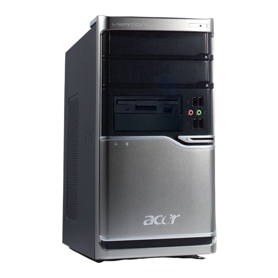
Aspire M5620 Front Panel The computer’s front panel consists of the following: Label Optical drive Card reader Power and HDD LED Power button Speaker or headphone Microphone jack USB ports Description... -
Page 19: Aspire M5620 Rear Panel
Aspire M5620 Rear Panel Label Description Power card socket Voltage selector switch Fan aperture PS/2 keyboard connector PS/2 mouse connector Serial port Printer connector Label Description Monitor connector USB 2.0 ports RJ-45 Ethernet connector Microphone jack Line-out jack Line-in jack... -
Page 20: Veritont661/M661/S661 Front Panel
VeritonT661/M661/S661 Front Panel Label Optical drive Floppy disk drive Power button Speaker or headphone jack Microphone jack USB ports Description... -
Page 21: Veritont661/M661/S661 Rear Panel
VeritonT661/M661/S661 Rear Panel Label Description Power card socket Voltage selector switch Fan aperture PS/2 keyboard connector PS/2 mouse connector Serial port Printer connector Label Description Monitor connector USB 2.0 ports RJ-45 Ethernet connector Microphone jack Line-out jack Line-in jack Extension card slots... -
Page 22: Hardware Specifications And Configurations
Intel / Conroe / Kensfield / Wolfdale / Yorkfield LGA 775 pin 800/1066 /1333 MHz 0 MHz (If Stop CPU Clock in Sleep State in BIOS Setup is set to Enabled.) Phoenix Award or AMI Kernel with Acer skin V6.0 SPI Flash 16Mb PXE 2.1 DMI V.2.0(s)or 2.1 SMBIOS 2.5... -
Page 23: Memory Combinations
Main Board Major Chips Item North Bridge Intel G33 South Bridge Intel ICH9R APG controller Intel G33 Super I/O controller ITE8718 Audio controller Realtek HD audio codec ALC888S HD codec 7.1 (co-lay with ALC888) LAN controller IT8718 HDD controller ITE8718 Keyboard controller ITE8718 Memory Combinations... -
Page 24: Audio Interface
Support to parity check feature Support to error correction code (ECC) feature Memory module combinations Audio Interface Item Audio controller Audio controller type Audio channel Audio function control Mono or stereo Compatibility Music synthesizer Sampling rate MPU-401 UART support Microphone jack Headphone jack You can install memory modules in any combination as long as they match the... -
Page 25: Sata Interface
SATA Interface Item SATA controller SATA controller resident bus Number of SATA channel Support bootable CD-ROM Floppy disk drive Interface Item Floppy disk drive controller Floppy disk drive controller resident bus ISA bus Support FDD format Parallel Port Item Parallel port controller Parallel port controller resident bus Number of parallel parts Support ECP/EPP... -
Page 26: Serial Port
Serial Port Item Serial port controller Serial port controller resident bus Number of serial port 16550 UART support Connector type Optional serial port I/O address (via BIOS setup) Optional serial port IRQ (via BIOS setup) USB Port Item Universal HCI USB Class USB Connectors Quantity Environmental Requirements... -
Page 27: Power Management
Power Management Devices Power Button USB Keyboard/Mouse Devices wake up from S3 should be less than Devices wake up from S5 should be less than 10 seconds Disabled Disabled Disabled Disabled Disabled Disabled Disabled Disabled Disabled Disabled Disabled Disabled... -
Page 29: Chapter 2 System Utilities
Chapter 2 System Utilities The manufacturer or the dealer already configures most systems. There is no need to run Setup when starting the computer unless you get a Run Setup message. The Setup program loads configuration values into the battery-backed nonvolatile memory called CMOS RAM. -
Page 30: Entering Setup
Entering Setup Power on the computer and the system will start POST (Power On Self Test) process. When the message of press the key of [Delete] to enter the setup menu. NOTE: If the message disappears before you respond and you still wish to enter Setup, restart the system by turning it OFF and On. - Page 31 The items in the main menu are explained below: Parameter Production Information Standard CMOS Features Advance BIOS FeaturesThis setup page includes all the items of Award special Advance Chipset Features Integrated Peripherals This setup page includes all onboard peripherals Power Management Setup PnP/PCI Configuration This setup page includes all configurations of PCI &...
-
Page 32: Product Information
Product Information The screen below appears if you select Product Information from the main menu: The Product Information menu contains general data about the system, such as the product name, serial number, BIOS version, etc. This information is necessary for troubleshooting (maybe required when asking for technical support). -
Page 33: Standard Cmos Features
Standard CMOS Setup Select standard CMOS features from the main menu to configure some basic parameters in your system the following screen shows the standard CMOS features menu:... - Page 34 The following table describes the parameters found in this menu. Parameter Date To set the date following the weekday-month-date-year format System Time To set the time following the hour-minute-second format Base Memory Size 640 K for system base memory Description Week: From [Sun.] to [Sat.].
- Page 35 Parameter Description Extended The BIOS determines how Memory Size much extended memory is present during the POST. This is the amount of memory located above 1MB in the memory address map of CPU Total Total memory size for the Memory system Size Hard disk drive connected...
-
Page 36: Advanced Bios Features
Advanced Setup The following screen shows the Advanced Setup: The following table describes the parameters found in this menu. Parameter Hard Disk Boot Priority Description This features displays the Hard Disk Boot Device priority from high to low and allows users to set the Hard Disk Boot Device Priority. - Page 37 Parameter Virus Warning This feature allows you to enable the VIRUS warning function for IDE Hard Disk boot sector protection. If this function is enabled and there is someone attempts to write data to this area, BIOS will show a warning message on screen and the alarm will beep.
-
Page 38: Advanced Chipset Setup
Advanced Chipset Setup The following table describes the parameters found in this menu. Parameter Dual Monitor Support Frame Buffer Size CPU Frequency Description This category allows you to enable or disable dual monitor support function This field displays how much frame buffer size of the system. - Page 39 Parameter Spread When the system clock generator pulses, the Spectrum extreme values of the pulse generate excess EMI. Enabling pulse spectrum spread modulation changes the extreme values from spikes to flat curves, thus reducing EMI. This benefit may in some case be outweighed by problems with timing-critical devices, such as a clock-sensitive SCSI device.
-
Page 40: Integrated Peripherals
Integrated Peripherals The following table describes the parameters found in this menu. Parameter IDE Function Setup This page allows you to setup IDE Onboard Device Setup Onboard I/O Chip Setup Description function This page allows you to setup onboard devices. This page allows you to setup onboard I/O chip. - Page 41 Integrated Peripherals-IDE Function Setup...
- Page 42 The following table describes the parameters found in this menu. Parameter The four IDE PIO fields let you set a PIO mode Primary/Seconda (0-4) for each of the four IDE devices that the ry Master/Slave onboard IDE interface supports. Modes 0 through 4 provide increased performance.
- Page 43 Parameter IDE HDD Block Block mode is also called block transfer, Mode multiple commands, or multiple sectors read/write. If your IDE hard drive supports block mode(most new drives do), select Enabled for automatic detection of the optimal number of block read/write per sector the drive can support.
- Page 44 The following table describes the parameters found in this menu. Parameter On Chip USB This field allows you to determine on chip USB type or disable on chip USB. UDB Memory Type Use this item to change the type of USB memory to shadow or Base memory.
- Page 45 Integrated Peripherals -Onboard I/O Chip Setup...
- Page 46 The following table describes the parameters found in this menu. Parameter Onboard FDC Select Enabled if your system has a floppy disk Controller controller (FDC) installed on the system board and you wish to use it. If you install an add-in FDC or the system has no floppy drive, select Disabled in this field.
-
Page 47: Power Management
Power Management The Power Management menu lets you configure your system to most effectively save energy while operating in a manner consistent with your own style of computer use. The following screen shows the Power Management parameters and their default settings:... - Page 48 The following table describes the parameters found in this menu. Parameter ACPI Function This item allows you to enable or disable the ACPI function ACPI Suspend This item specifies the power saving Type modes for ACPI function. S1 (POSP: The S1 sleep mode is a low power state..
- Page 49 Parameter Soft-off by When Enabled, turning the system PWR/BTTN off with the on/off button places the system in a very low-power-usage state, with only enough circuitry receiving power to detect power button activity or Resume by Ring activity. WOL (PME#) This category enables or disables From Soft-Off wake-on-Lan from soft-off...
-
Page 50: Pnp/Pci Configuration
PCI/PnP Setup... - Page 51 The following table describes the parameters found in this menu. Parameter Init Display Initialize the AGP video display before initializing First any other display device on the system. Thus the AGP display becomes the primary display. Reset Normally, you leave this field Disabled. Select Configuration Enabled to reset Extended System Configuration Data...
-
Page 52: Pc Health Status
PC Health Status... -
Page 53: Frequency/Voltage Control
The following table describes the parameters found in this menu: Parameter V core CPU Temperature CPU/SYSTEM FAN Speed (RPM) CPU Smart FAN Control Frequency/Voltage Control CMOS Setup Utility - Copyright (C) 1985-2005,American Megatrends,Inc. Manufacturer: Intel Ratio Status: Unlocked (Min:06,Max:10) Ratio Actual Value: 10 CPU Frequency Auto Detect DIMM/PCI CLK Spread Spectrum... - Page 54 The following table describes the parameters found in this menu: Parameter Auto Detect This option allows you to DIMM/PCI CLK enable/disable the feature of auto detecting the clock frequency of the installed PCI bus. Manufacturer This item specifies CPU Manufacturer CPU frequency This item specifies CPU frequency Spread Spectrum...
-
Page 55: Load Default Settings
Load Default Settings This option opens a dialog box that lets you install defaults for all appropriate items in the Setup Utility. Parameter Load Default Select the field loads the factory defaults for BIOS Settings and Chipset Features, which the system automatically detects. -
Page 56: Set Supervisor/User Password
Set Supervisor/User Password When this function is selected, the following message appears at the center of the screen to assist you in creating a password. - Page 57 Parameter When this function is selected, the following Supervisor/User message appears at the center of the screen to Password assist you in creating a password. ENTER PASSWORD Type the password, up to eight characters, and press<Enter>. The password typed now will clear any previously entered password from CMOS Memory.
-
Page 58: Save & Exit Setup
Save & Exit Setup Highlight this item and press <Enter> to save the changes that you have made in the Setup Utility and exit the Setup Utility. Parameter Save & Exit Setup Press <Enter> to save the changes that have made Description in the Setup Utility and exit the Setup Utility. -
Page 59: Exit Without Saving
Exit Without Saving Highlight this item and press <Enter> to discard any changes that you have made in the Setup Utility and exit the Setup Utility. Parameter Exit Without Saving Description Press<Enter> to discard any changes and exit the Setup Utility Options... -
Page 60: Chapter 3 Machine Disassembly And Replacement
Machine Disassembly and Replacement To disassemble the computer, you need the following tools: Wrist grounding strap and conductive mat for preventing electrostatic discharge. Wire cutter. Phillips screwdriver (may require different size). NOTE: The screws for the different components vary in size. During the disassembly process, group the screws with the corresponding components to avoid mismatches when putting back the components. -
Page 61: General Information
General Information Before You Begin Before proceeding with the disassembly procedure, make sure that you do the following: 1. Turn off the power to the system and all peripherals. 2. 2.Unplug the AC adapter and all power and signal cables from the system... -
Page 62: Disassembly Procedure
Disassembly Procedure This section tells you how to disassemble the system when you need to perform system service. Please also refer to the disassembly video, if available. CAUTION: Before you proceed, make sure you have turned off the system and all peripherals connected to it. -
Page 63: Aspire M5620 Disassembly Procedure
Aspire M5620 Standard Disassembly Process... -
Page 71: Veritont661/M661/S661 Disassembly Procedure
VeritonT661/M661/S661 Standard Disassembly Process... -
Page 79: Chapter 4 Troubleshooting
Troubleshooting Please refer to generic troubleshooting guide for troubleshooting information relating to following topics: Power-On Self-Test (POST) POST Check Points POST Error Messages List Error Symptoms List Chapter 4... -
Page 80: Chapter 5 Jumper And Connector Information
Chapter 5... - Page 82 ATX_POWER: ATX 24-pin Power Connector Signal Name +3.3 +3.3 PWR OK 5VSB +12V +12V +3.3V Signal Name +3.3V -12V PS_ON...
- Page 86 Signal Name STROBE BUSY SLCT Signal Name ERROR INIT SLCTIN GROUND GROUND GROUND GROUND GROUND GROUND GROUND GROUND...
-
Page 89: Chapter 6 Fru (Field Replaceable Unit) List
SERVICE PROVIDERS, your Acer office may have a DIFFERENT part number code to those given in the FRU list of this printed Service Guide. You MUST use the local FRU list provided by your regional Acer office to order FRU parts for repair and service of customer machines. -
Page 90: Exploded Diagram
Exploded Diagram DESCRIPTION AM30_MAIN_BEZEL AM50_USB AM50_USB_PANEL FDD_LOCK_SLIDE CD_ROM LOCK SLIDE CHASSIS USB_PCB_ASN USB-SHIELDING RIGHT SIDE DOCR DESCRIPTION POWER SUPPLY PCI-BRACKET LEFT SIDE DOOR HOTHER BOARD 3.5 DEVICE CD-ROM HDD-LOCK-SLIDE... - Page 91 DESCRIPTION TOP-SHOELD 3.25 ROTATE COVER CD-ROM HDD-LOCK-SLIDE FDD-LOCK-SLIDE DESCRIPTION CDROM-LOCK-SLIDE RIGHT-SIDE USB MODULE CHASSIS POWER-SUPPLY LEFT-SCDE MAINBOARD...