Table of Contents
Advertisement
Quick Links
Advertisement
Table of Contents

Related Manuals for Agilent Technologies 8697


Summary of Contents for Agilent Technologies 8697
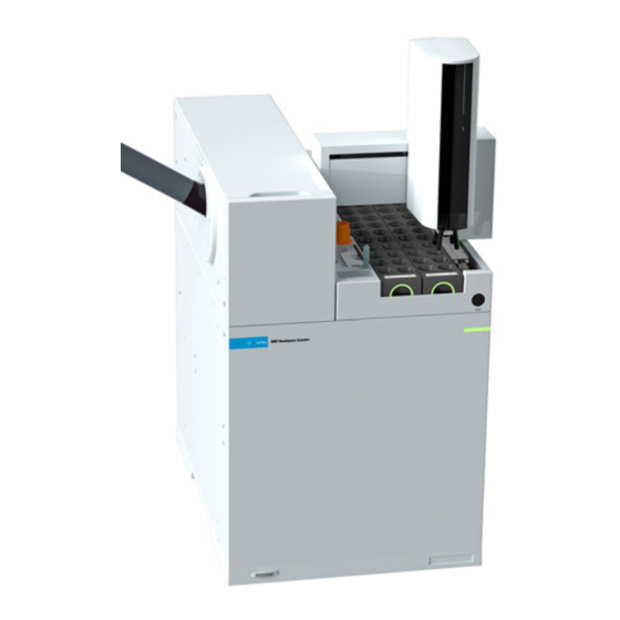
- Page 1 Agilent 8697 Headspace Sampler Maintenance...
- Page 2 Notices Warranty Safety Notices © Agilent Technologies, Inc. 2021 No part of this manual may be reproduced in The material contained in this document is any form or by any means (including provided “as is,” and is subject to being...
-
Page 3: Table Of Contents
Contents About Maintaining the Headspace Sampler Overview of Maintenance Where to find a procedure GC and Headspace Automated Maintenance Procedures Tools and Materials Required for Maintenance Safety Removing Covers and Components Automated Maintenance Procedures and Covers Install/Remove the Transfer Line Support Bracket Remove the Pneumatics Cover Remove the Valve Thermal Enclosure Install the Valve Thermal Enclosure... - Page 4 Remove the Fused Silica Column from the Transfer Line Install a Fused Silica Column into the Transfer Line Use ProSteel Tubing Replace Gripper Pads Manually Remove Vials in the Oven Consumables and Parts Consumables and Parts for the Agilent 8697 Headspace Sampler Maintenance Manual...
- Page 5 About Maintaining the Headspace Sampler Overview of Maintenance 6 GC and Headspace Automated Maintenance Procedures 7 Tools and Materials Required for Maintenance 8 Safety 8 This section provides an overview of the maintenance procedures included in this document. It also lists the tools needed for routine maintenance and the safety information one should be aware of before performing a maintenance task.
-
Page 6: About Maintaining The Headspace Sampler
Overview of Maintenance Overview of Maintenance This manual details the routine tasks needed to maintain the 8697 Headspace Sampler (Headspace). The procedures assume a basic knowledge of tool use and of Headspace operation. Readers are, for example, expected to know how to: •... -
Page 7: Gc And Headspace Automated Maintenance Procedures
About Maintaining the Headspace Sampler GC and Headspace Automated Maintenance Procedures GC and Headspace Automated Maintenance Procedures As a part of the GC system, the Headspace responds to GC maintenance requests. When the GC begins an automated maintenance task, the Headspace settings will change appropriately. The GC will not begin automated maintenance if the Headspace is preparing samples. -
Page 8: Tools And Materials Required For Maintenance
Clean, lint-free gloves Pencil magnet (for placing a valve rotor) Shop vacuum/vacuum cleaner (for cleaning up broken vial glass) Safety Before performing a maintenance task, read the important safety and regulatory information found in the 8697 Headspace Sampler Safety manual. Maintenance Manual... -
Page 9: Removing Covers And Components
Removing Covers and Components Automated Maintenance Procedures and Covers 10 Install/Remove the Transfer Line Support Bracket 11 Remove the Pneumatics Cover 12 Remove the Valve Thermal Enclosure 13 Install the Valve Thermal Enclosure 14 Remove the Pneumatics Assembly 15 Remove the Valve/Loop Cover 18 Remove the Tray Assembly 19 This section describes how to remove covers and components as needed for routine maintenance. -
Page 10: Automated Maintenance Procedures And Covers
Removing Covers and Components Automated Maintenance Procedures and Covers Automated Maintenance Procedures and Covers Normally, removing covers is performed as part of some other maintenance. If using the automated maintenance procedures, that procedure will cool down any hot parts and will show you how to remove the covers as needed. -
Page 11: Install/Remove The Transfer Line Support Bracket
Removing Covers and Components Install/Remove the Transfer Line Support Bracket Install/Remove the Transfer Line Support Bracket 1 If necessary, remove any existing ALS post from the mounting hole next to the transfer line. 2 Place the transfer line support bracket on the inlet carrier cover. The locater holes in the support bracket should align over the holes for the inlet ALS injector post and the raised mounting detail. -
Page 12: Remove The Pneumatics Cover
Removing Covers and Components Remove the Pneumatics Cover Remove the Pneumatics Cover The pneumatics cover protects the valve thermal enclosure and transfer line. To remove the pneumatics cover: 1 Press the Park button on the front of the tray to “park” the tray. 2 Remove the T-20 screw that secures the cover in place (Figure Pneumatics cover... -
Page 13: Remove The Valve Thermal Enclosure
Removing Covers and Components Remove the Valve Thermal Enclosure Remove the Valve Thermal Enclosure The valve thermal enclosure protects the 6 port valve and sample loop. To remove the valve thermal enclosure: 1 Remove the pneumatics cover. See “Remove the Pneumatics Cover” on page 12. -
Page 14: Install The Valve Thermal Enclosure
Removing Covers and Components Install the Valve Thermal Enclosure Install the Valve Thermal Enclosure To install the valve thermal enclosure: 1 Locate the valve thermal enclosure’s transfer line cutout, and align it with the transfer line (Figure Transfer line cutout Figure 5. -
Page 15: Remove The Pneumatics Assembly
Removing Covers and Components Remove the Pneumatics Assembly Remove the Pneumatics Assembly Remove the pneumatics assembly (Figure 6) to access the oven components. Figure 6. Pneumatics assembly without covers To remove the pneumatics assembly: 1 Set your GC oven, Headspace oven, sample loop, and transfer line to ambient temperatures and wait for them to cool. - Page 16 Removing Covers and Components Remove the Pneumatics Assembly 7 Loosen the 3/16-inch nut in the internal reducer (Figure 7). (Stabilize the valve fitting using a 1/4-inch wrench.) Figure 7. 3/16-inch internal reducer with valve cover removed. 8 Remove the fused silica column from the internal reducer. 9 Loosen the 1/4-inch nut and remove the reducer fitting.
- Page 17 Removing Covers and Components Remove the Pneumatics Assembly 11 Loosen the 6 screws that secure the pneumatics assembly to the chassis. Note that one screw is on the side of the assembly. (Figure Figure 8. Loosen the screws that secure the pneumatics assembly Do not remove the pneumatics assembly completely.
-
Page 18: Remove The Valve/Loop Cover
Removing Covers and Components Remove the Valve/Loop Cover Remove the Valve/Loop Cover 1 Gather the following: • T-20 Torx driver 2 Remove the pneumatics cover. See “Remove the Pneumatics Cover” on page 12. 3 Remove the valve thermal enclosure. See “Remove the Valve Thermal Enclosure”... -
Page 19: Remove The Tray Assembly
Removing Covers and Components Remove the Tray Assembly Remove the Tray Assembly 1 Gather the following: • Lint-free gloves 2 Set your GC oven, Headspace oven, and transfer line to ambient temperatures and wait for them to cool. 3 Once the GC oven, Headspace oven, and transfer line have cooled to ambient temperature, turn the Headspace off and unplug the power cord. - Page 20 Removing Covers and Components Remove the Tray Assembly Maintenance Manual...
-
Page 21: Maintenance
Install a Fused Silica Column into the Transfer Line 52 Use ProSteel Tubing 57 Replace Gripper Pads 58 Manually Remove Vials in the Oven 59 This section provides the basic maintenance procedures for the Agilent 8697 Headspace Sampler. Maintenance Manual... -
Page 22: Clean The Sample Tray Assembly
Maintenance Clean the Sample Tray Assembly Clean the Sample Tray Assembly Wear clean, lint-free gloves to prevent contamination of parts with dirt and skin oils. C AU T I O N The following describes how to clean the sample tray assembly. 1 Gather the following. - Page 23 Maintenance Clean the Sample Tray Assembly 6 Clean the Headspace tray and mainframe surfaces of any spills or broken glass that may have fallen through the tray assembly base. a Clean any broken glass on the Headspace tray surface using a vacuum cleaner or other appropriate technique.
-
Page 24: Clean The Oven
Maintenance Clean the Oven Clean the Oven 1 Gather the following: • Lint-free gloves • Lint-free wipes • T-20 Torx driver • 1/8-inch hex key wrench • Needle nose pliers • Shop vacuum 2 Start the automated procedure: Maintenance > Headspace > Perform Maintenance > Clean Oven >... - Page 25 Maintenance Clean the Oven 8 Disconnect the oven top assembly from the oven and set aside. a Remove four T-20 Torx screws from the oven top assembly (Figure 12). Figure 12. Remove T-20 Torx screws from the oven top assembly b Completely loosen the two T-20 Torx captive thumbscrews (Figure 13).
- Page 26 Maintenance Clean the Oven The ribbon heater edges are sharp. Broken glass edges are sharp. Wear protective gloves to WAR N IN G avoid personal injury The carousel and oven can contain sample residue. When handling/cleaning broken glass and sample residue within the headspace sampler, all applicable local and national laboratory safety practices must be followed.
- Page 27 Maintenance Clean the Oven b Remove three T-20 Torx screws from the center of the carousel (Figure 15). Carousel Figure 15. Removing the carousel c Carefully lift the carousel out of the oven assembly. d Clean up any sample residue or broken glass inside the carousel using a chemical spill protocol appropriate for the sample (including personal protective equipment, or PPE).
- Page 28 Maintenance Clean the Oven Ribbon heater Central area Figure 16. Cleaning the oven area 11 Reassembly is the reverse of these steps. After restoring power to the HS, recalibrate the system. On the GC touchscreen or in the browser interface, go to ettings >...
-
Page 29: Replace The Sample Probe
Maintenance Replace the Sample Probe Replace the Sample Probe Wear clean, lint-free gloves to prevent contamination of parts with dirt and skin oils. C AU T I O N 1 Gather the following: • Sample probe G4556-63825 • Lint-free gloves •... - Page 30 Maintenance Replace the Sample Probe 7 Using a 1/4-inch wrench, loosen the sample probe connection on the 6 port valve and remove the sample probe fitting from the valve. Sample loop ends on 6 port valve 6 port valve Sample loop Figure 18.
-
Page 31: Replace The Sample Loop
Maintenance Replace the Sample Loop Replace the Sample Loop Wear clean, lint-free gloves to prevent contamination of parts with dirt and skin oils. C AU T I O N 1 Gather the following: • Lint-free gloves • Sample loop (see Table •... - Page 32 Maintenance Replace the Sample Loop 7 Using a 1/4-inch wrench, disconnect the two sample loop ends from the 6 port valve (Figure 19). Sample loop ends on 6 port valve 6 port valve Sample loop Figure 19. Disconnect the sample loop from the 6 port valve 8 Using a 1/4-inch wrench, loosen the sample probe connection on the 6 port valve.
- Page 33 Maintenance Replace the Sample Loop 12 With the sample loop in front of the 6 port valve, connect both ends of the new sample loop to positions 1 and 4 as shown in Figure Port 4 Valve rotor Port 3 Port 5 Mounting hole Mounting hole...
-
Page 34: Replace The Sample Loop Adapters
Maintenance Replace the Sample Loop Adapters Replace the Sample Loop Adapters Different size sample loops require different sample loop adapters. Normally, only change or replace the sample loop adapters when changing sample loop size. A full set of adapters shipped with the Headspace. Wear clean, lint-free gloves to prevent contamination of parts with dirt and skin oils. - Page 35 Maintenance Replace the Sample Loop Adapters 3 Use Table 2 to select the appropriate adapters for your sample loop size. Table 2 Sample loop adapters Sample loop size Adapter p/n Quantity Installation location 0.025 mL G4556-20177 Sample loop block G4556-20178 Valve/loop cover 0.050 mL G4556-20177...
-
Page 36: Replace The 6 Port Valve
Maintenance Replace the 6 Port Valve Replace the 6 Port Valve Wear clean, lint-free gloves to prevent contamination of parts with dirt and skin oils. C AU T I O N 1 Gather the following: • T-20 Torx driver • Lint-free gloves •... - Page 37 Maintenance Replace the 6 Port Valve 7 Disconnect the transfer line from the 6 port valve. a Loosen the 3/16-inch nut in the internal reducer. (Use a 1/4-inch wrench to stabilize the 1/4-inch nut). b Remove the fused silica column from the internal reducer. c Loosen the 1/4-inch nut and remove the reducer fitting.
- Page 38 Maintenance Replace the 6 Port Valve 12 Orient the new valve as shown below. Port 1 should be at the bottom, and port 4 at the top. Port 4 Port 3 Port 5 Port 2 Port 6 Port 1 13 Install the new valve. Make sure the stator is oriented correctly and engaged with the 6 port valve motor coupler.
-
Page 39: Replace The 6 Port Valve Rotor
Maintenance Replace the 6 Port Valve Rotor Replace the 6 Port Valve Rotor 1 Gather the following: • Lint-free gloves • 1/4-inch wrench • Pencil magnet 2 Start the automated procedure: Maintenance > Headspace > Perform Maintenance > Replace Six Port Valve Rotor > Start Maintenance. If not using the automated procedure, set your GC oven, Headspace oven, sample loop, and transfer line to ambient temperatures and wait for them to cool. - Page 40 Maintenance Replace the 6 Port Valve Rotor 9 Using a small pencil magnet, set the new rotor in place on the 6 port valve with the rotor ID letter facing port 4 (Figure 24). Port 4 Valve rotor Port 3 Port 5 Mounting hole Mounting hole...
-
Page 41: Clean The 6 Port Valve And Rotor
Maintenance Clean the 6 Port Valve and Rotor Clean the 6 Port Valve and Rotor Wear clean, lint-free gloves to prevent contamination of parts with dirt and skin oils. C AU T I O N Be careful to not damage the rotor and valve in any way. The rotor must be replaced if any C AU T I O N damage is found. -
Page 42: Attach The Transfer Line To A Split Splitless Or Multimode Inlet
Maintenance Attach the Transfer Line to a Split Splitless or Multimode Inlet Attach the Transfer Line to a Split Splitless or Multimode Inlet Wear clean, lint-free gloves to prevent contamination of parts with dirt and skin oils. C AU T I O N 1 Gather the following: •... - Page 43 Maintenance Attach the Transfer Line to a Split Splitless or Multimode Inlet 10 Install the inlet liner (with o-ring) that is appropriate for your application. If desired, remove the transfer line support bracket so inlet maintenance is easier. See “Install/Remove the Transfer Line Support Bracket”...
-
Page 44: Attach The Transfer Line To A Volatiles Interface
Maintenance Attach the Transfer Line to a Volatiles Interface Attach the Transfer Line to a Volatiles Interface Wear clean, lint-free gloves to prevent contamination of parts with dirt and skin oils. C AU T I O N 1 Gather the following: •... - Page 45 Maintenance Attach the Transfer Line to a Volatiles Interface 8 Use a column cutter to trim approximately 1 cm from the leading edge of the fused silica. a Score the column using a glass scribing tool. The score must be square to ensure a clean break.
-
Page 46: Attach The Transfer Line To A Purged Packed Inlet
Maintenance Attach the Transfer Line to a Purged Packed Inlet Attach the Transfer Line to a Purged Packed Inlet Wear clean, lint-free gloves to prevent contamination of parts with dirt and skin oils. C AU T I O N 1 Gather the following: •... - Page 47 Maintenance Attach the Transfer Line to a Purged Packed Inlet 14 Finger tighten the bracket thumbscrew to secure the transfer line in the support bracket. 15 Heat the purged packed inlet to operating temperature. 16 Retighten the fittings, if necessary. Refer to the documentation supplied with your GC for more information.
-
Page 48: Attach The Transfer Line To A Cool On-Column Inlet
Maintenance Attach the Transfer Line to a Cool On-Column Inlet Attach the Transfer Line to a Cool On-Column Inlet Make sure your column dimensions are correct in relation to the size of your fused silica. Your column id can not be greater than 530 um. Refer to your cool on-column inlet documentation for more information. -
Page 49: Remove The Transfer Line From The Gc
Maintenance Remove the Transfer Line from the GC Remove the Transfer Line from the GC Wear clean, lint-free gloves to prevent contamination of parts with dirt and skin oils. C AU T I O N 1 Gather the following: • 3/16-inch open end wrench (provided in ship kit) •... -
Page 50: Disconnect The Transfer Line From The Gc
Maintenance Disconnect the Transfer Line from the GC Disconnect the Transfer Line from the GC Hot surfaces. If not using an automated maintenance procedure, cool down the GC inlet, WAR N IN G GC oven, HS sample loop, transfer line, and other heated zones to a safe handling temperature. -
Page 51: Remove The Fused Silica Column From The Transfer Line
Maintenance Remove the Fused Silica Column from the Transfer Line Remove the Fused Silica Column from the Transfer Line 1 Follow the procedure “Disconnect the Transfer Line from the GC” on page 50. 2 Loosen the 3/16-inch nut in the internal reducer. (Use a 1/4-inch wrench to stabilize the 1/4-inch nut). -
Page 52: Install A Fused Silica Column Into The Transfer Line
Maintenance Install a Fused Silica Column into the Transfer Line Install a Fused Silica Column into the Transfer Line Wear clean, lint-free gloves to prevent contamination of parts with dirt and skin oils. C AU T I O N Transfer line bends with a bend radius of less than 75 mm are not recommended. C AU T I O N However, if a sharp bend is necessary to route the transfer line, be sure the bend radius is at least 35 mm. - Page 53 Maintenance Install a Fused Silica Column into the Transfer Line 6 The transfer line will install in valve port 3 (at the 10 O’clock position), as shown in Figure Valve Port 3 Figure 25. Valve Port 3 The transfer line installs using a 1/16-inch internal reducer, as shown in Figure 26.
- Page 54 Maintenance Install a Fused Silica Column into the Transfer Line 8 Slide the stainless steel ferrule over the 1/16-inch tube end of the reducer, then install into the open valve port. Finger-tighten, then tighten 1/4-turn more (Figure 27). Figure 27. Installing into the open valve port 9 Gently straighten the transfer line.
- Page 55 Maintenance Install a Fused Silica Column into the Transfer Line 12 Assemble the 3/16-inch nut and polyimide ferrule onto the fused silica tubing as shown below. 3/16-inch nut Tubing Polyimide ferrule 13 Use a column cutter to trim approximately 1 cm from the leading edge of the fused silica. a Score the column using a glass scribing tool.
- Page 56 Maintenance Install a Fused Silica Column into the Transfer Line 14 Gently guide the fused silica into the reducer fitting (the 1/4-inch nut already in the 6 port valve) all the way in until it stops. Slide the polyimide ferrule and 3/16-inch nut into the 1/4-inch nut.
-
Page 57: Use Prosteel Tubing
Maintenance Use ProSteel Tubing Use ProSteel Tubing If you wish to use ProSteel tubing in place of fused silica in the transfer line, the installation and removal procedures for ProSteel tubing are similar to the fused silica procedures except for the following steps: 1 Cut a ProSteel metal capillary (0.53 mm ID with maximum OD of 0.67 mm) to approximately 1 m in length using a precision tubing cutter. -
Page 58: Replace Gripper Pads
Maintenance Replace Gripper Pads Replace Gripper Pads 1 Start the automated procedure: Maintenance > Headspace > Perform Maintenance > Replace Gripper Pads. 2 Park the tray. 3 Remove the vial racks. 4 Gently move the gantry forward so that the gripper is accessible. 5 Holding the gripper with one hand, remove each gripped pad by slowly pulling down, rotating the pad as needed. -
Page 59: Manually Remove Vials In The Oven
Maintenance Manually Remove Vials in the Oven Manually Remove Vials in the Oven To manually remove any vials in the oven carousel, do the following: 1 On the GC touchscreen or browser interface, go to Diagnostics > Headspace > Manual Operations, then select the option to empty the oven of all vials. - Page 60 Maintenance Manually Remove Vials in the Oven Maintenance Manual...
- Page 61 Consumables and Parts Consumables and Parts for the Agilent 8697 Headspace Sampler 62 This section lists the consumables and parts for the Agilent 8697 Headspace Sampler. Maintenance Manual...
- Page 62 Consumables and Parts Consumables and Parts for the Agilent 8697 Headspace Sampler Consumables and Parts for the Agilent 8697 Headspace Sampler See the Agilent catalog for consumables and supplies for a more complete listing, or visit the Agilent Web site for the latest information (www.agilent.com).
- Page 63 Consumables and Parts Consumables and Parts for the Agilent 8697 Headspace Sampler Table 5 Headspace sampler transfer line parts Description Part number Transfer line components Ferrule, polyimide, graphite, 5/pk 0.53 mm, 1/32 in. for tubing OD 0.50 x 0.80 mm 0100-2595 0.4 mm id, for columns up to 250 µm od...
- Page 64 A-Line electronic crimper for 20mm caps 5191-5615 A-Line electronic decapper for 20mm cap 5191-5613 Ergonomic manual crimper for 20 mm caps 5040-4669 Ergonomic manual decapper for 20 mm caps 5040-4671 www.agilent.com Agilent Technologies, Inc. 2021 Second edition, January 2021 *G4511-90001* G4511-90005...