Table of Contents
Advertisement
Quick Links
Published 08/10
This Operator's Manual is an integral part of the safe operation of this machine and must
be maintained with the unit at all times. READ, UNDERSTAND, and FOLLOW the Safety
and Operation Instructions contained in this manual before operating the equipment. C01-
Cover
®
BUSH HOG
2501 Griffin Ave.
Selma, AL 36703
334-874-2700
www.bushhog.com
OPERATOR'S MANUAL
© 2010 Alamo Group Inc.
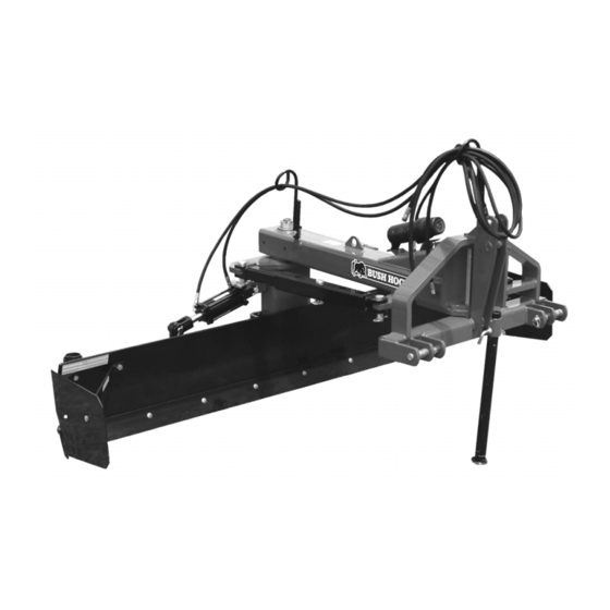
100 Series
REAR MOUNTED BLADE
00786975C
Part No.
$0.00
Advertisement
Table of Contents

Related Manuals for Bush Hog BUSH HOG FC-BL-0002


Summary of Contents for Bush Hog BUSH HOG FC-BL-0002
- Page 1 This Operator's Manual is an integral part of the safe operation of this machine and must be maintained with the unit at all times. READ, UNDERSTAND, and FOLLOW the Safety and Operation Instructions contained in this manual before operating the equipment. C01- Cover ® BUSH HOG 2501 Griffin Ave. Selma, AL 36703 334-874-2700 www.bushhog.com...
- Page 2 To the Owner/Operator/Dealer All implements with moving parts are potentially hazardous. There is no substitute for a cautious, safe-minded operator who recognizes the potential hazards and follows reasonable safety practices. The manufacturer has designed this implement to be used with all its safety equipment properly attached to minimize the chance of accidents.
-
Page 3: Table Of Contents
TABLE OF CONTENTS SAFETY SECTION ...1-1 Safety Messages ... 1-2 Decal Location ... 1-9 Decal Description ... 1-11 Federal Laws and Regulations ... 1-15 INTRODUCTION SECTION...2-1 ASSEMBLY SECTION ...3-1 Planer Wheel ... 3-3 Operation - Special Notice ... 3-3 Gauge Wheel (Extra Equipment) ... 3-5 Skid Shoes &... -
Page 5: Safety Section
SAFETY SECTION Safety Section 1-1... -
Page 6: Safety Messages
Safety Messages A careful operator is the best operator. Safety is of primary importance to the manufacturer and should be to the owner/operator. Most accidents can be avoided by being aware of your equipment, your surroundings, and observing certain precautions. The first section of this manual includes a list of Safety Messages that, if followed, will help protect the operator and bystanders from injury or death. - Page 7 Never operate the Tractor or Implement until you have read and completely understand this Manual, the Tractor Operator’s Manual, and each of the Safety Messages found in the Manual or on the Tractor and Implement. Learn how to stop the tractor engine suddenly in an emergency.
- Page 8 Never allow children to operate, ride on, or come close to the Tractor or Implement. Usually, 16-17 year-old children who are mature and responsible can operate the implement with adult supervision, if they have read and understand the Operator’s Manuals, been trained in proper operation of the tractor and Implement, and are physically large enough to reach and operate the controls easily.
- Page 9 PROLONGED PERMANENT HEARING LOSS! Tractors with or without an Implement attached can often be noisy enough to cause permanent hearing loss. We recommend that you always wear hearing protection if the noise in the Operator’s position exceeds 80db. extended period of time will cause severe hearing loss. Noise over 90db adjacent to the Operator over an extended period of time will cause permanent or total hearing loss.
- Page 10 Periodically inspect all moving parts for wear and replace when necessary with authorized service parts. Look for loose fasteners, worn or broken parts, and leaky or loose fittings. Make sure all pins have cotter pins and washers. Serious injury may occur from not maintaining this machine in good working order.
- Page 11 Operate the Tractor and/or Implement controls only while properly seated in the Tractor seat with the seat belt securely fastened around you. Implement may cause serious injury or death. Be particularly careful when transporting the Implement with the Tractor. Turn curves or go up hills only at a low speed and using a gradual steering angle.
- Page 12 These parts are made and tested to Bush Hog specifications. Non-genuine "will fit" parts do not consistently meet these specifications. The use of “will fit” parts may reduce equipment performance, void warranties, and present a safety hazard. Use genuine Bush Hog parts for economy and safety.
-
Page 13: Decal Location
SAFETY Decal Location NOTE: Bush Hog supplies safety decals on this product to promote safe operation. Damage to the decals may occur while in shipping, use, or reconditioning. Bush Hog cares about the safety of its customers, operators, and bystanders, and will replace the safety decals on this product in the field, free of charge (Some shipping and handling charges may apply). - Page 14 NAME SER PLT REFLECT REFLECT ___________ MANUAL Safety Section 1-10 DESCRIPTION Translate Safety Material Oil Penetration Genuine Bush Hog Parts Multi-Hazard for Blades Multi-Hazard General SMV Emblem Grease Fitting Inside Notice to Owner Bush Hog 100-08 100-09 Serial Plate Red Reflector...
-
Page 15: Decal Description
Decal Description Peligro Translation, If you do not know how to read English, please find someone who knows how to read English. P/N 00725746 WARNING! Failure to INSPECT and REPAIR or REPLACE Hoses may allow worn Hoses to rupture SUDDENLY and VIOLENTLY with resulting serious BODILY INJURY from SCALDING or FIRE with resulting BURN INJURY or DEATH. - Page 16 WARNING!- Multiple Hazard and General Safety P/N 999200 Slow Moving Vehicle Decal. Keep SMV reflector clean and visible. DO NOT transport or operate without the SMV. P/N 03200347 Information that Grease Fitting is present and must apply grease P/N 000678 Operator's Manual (with repair parts) and warranty was attached to this implement during final inspection.
- Page 17 Logo Product Name: Bush Hog P/N 00786979 LOGO PRODUCT NAME: 100-08 P/N 00786981 LOGO PRODUCT NAME: 100-09 P/N 00786988 Red Reflector. Keep reflectors clean and visible. P/N 1458392 100 Series 08/10 © 2010 Alamo Group Inc. SAFETY Safety Section 1-13...
- Page 18 Amber Reflector. Keep reflectors clean and visible. P/N 1458393 Read Operator’s Manual! The operator’s manual is located inside this canister. If the manual is missing order one from your dealer. P/N 00776031 100 Series 08/10 © 2010 Alamo Group Inc. SAFETY Safety Section 1-14...
-
Page 19: Federal Laws And Regulations
This section is intended to explain in broad terms the concept and effect of federal laws and regulations concerning employer and employee equipment operators. This section is not intended as a legal interpretation of the law and should not be considered as such. Employer-Employee Operator Regulations U.S. -
Page 21: Introduction Section
INTRODUCTION SECTION Introduction Section 2-1... - Page 22 This 100 Series is designed with care and built with quality materials by skilled workers. Proper assembly, maintenance, and operating practices, as described in this manual, will help the owner/operator get years of satisfactory service from the machine. The purpose of this manual is to familiarize and instruct. The Assembly Section instructs the owner/operator in the correct assembly of the Blade using standard and optional equipment.
- Page 23 The 100 Series Blade is available in widths of 8' and 9' and features a heavy-duty CAT I-II three-point hitch and CAT II quick-hitch. The 9' model is rated for up to 95 PTO HP wheel-type tractors. The 100 Series blade is available with either hydraulic or manual adjustments of the mainframe swing, moldboard tilt to better fit many applications.
- Page 24 INTRODUCTION Attention Owner/Operator BEFORE OPERATING THIS MACHINE: 1. Carefully read the Operator’s Manual, completely understand the Safety Messages and instructions, and know how to operate correctly both the tractor and implement. 2. Fill out the Warranty Card in full. Be sure to answer all questions, including the Serial Number of the implement.
-
Page 25: Assembly Section
ASSEMBLY SECTION Assembly Section 3-1... - Page 26 Additional accessories are provided for use with the Planer Wheel: Hydraulic Cylinder or Ratchet Jack. Your Bush Hog 100 Series is designed to be used with either a standard Category 1 or 2, 3-Point Hitch or Quick Coupler. The Category 2, 3-Point, is standard. To convert to Category 1, 3-Point, it is necessary to remove the Special Bushing in the Upper Link.
-
Page 27: Planer Wheel
Planer Wheel If the Planer Wheel is to be used, it will be necessary to drill (2) holes, 0.688 diameter. See illustration below. When mounting the Hydraulic Cylinder to the Planer Wheel Assembly, it is recommended by the manufacturer that the Rod End be attached to the Lug on the Planer Wheel Beam Weldment, as shown in the illustration below. - Page 28 ASSEMBLY Attach the Moldboard Pivot Cylinder as shown in Figure Asm-0003 or optional Manual Adjusting Links. Attach the Mainframe Swing Cylinder as shown in Figure Asm-0004 or optional Manual Adjusting Links. 100 Series 08/10 Assembly Section 3-4 © 2010 Alamo Group Inc.
-
Page 29: Gauge Wheel (Extra Equipment)
ASSEMBLY Gauge Wheel (Extra Equipment) Mounting Holes must be drilled, for mounting the Gauge Wheel to the Mainframe (See Planner Wheel illustration in Maintenance Section 5-2.) Dual or Single Wheels with laminated puncture proof or pneumatic tires are optional. Assembly of the Hydraulic Cylinder to the Gauge Wheel Beam must be in the direction as shown in Figure Asm-0005. -
Page 30: Hydraulic System
When installing this Valve, observe all safety precautions as hydraulic lines are under high pressure (2500 PSI). If additional information is required concerning your hydraulic system, contact your Bush Hog dealer. (Figure Asm-0008). 100 Series 08/10 © 2010 Alamo Group Inc. ASSEMBLY... -
Page 31: Hydraulic Control Valve (Accessory Equipment)
Hydraulic Control Valve (Accessory Equipment) A 3-Spool 4 way Hydraulic Control Valve, open center or closed center, is available as Accessory Equipment. This allows you to operate 4 Hydraulic Cylinders from two remote outlets. Connect the 3- Spool Valve to one outlet to operate three Cylinders. -
Page 33: Operation Section
OPERATION SECTION Operation Section 4-1... -
Page 34: Operation Instructions
BUSH HOG 100 SERIES REAR MOUNTED BLADE OPERATION INSTRUCTIONS Your Bush Hog 100 Series should now be assembled and inspected for any evidence of defective or damaged parts before use. Any evidence of damage should be reported to your dealer immediately. -
Page 35: Standard Equipment And Specifications
Standard Equipment and Specifications Max. 2-Wheel Drive Tractor HP (PTO): 8’ 9’ Max. Front Wheel Assist Tractor HP (PTO): 8’ 9’ Moldboard Width Moldboard Dimension Cutting Edge Support Stand Hitch King Pin Diameter Adjustment Types Offset (Maximum Left or Right) Forward Pivot Reverse Pivot Tilt (Up and Down) -
Page 36: Operator Requirements
2. OPERATOR REQUIREMENTS Safe operation of the unit is the responsibility of a qualified operator. A qualified operator has read and understands the implement and tractor Operator’s Manuals and is experienced in implement and tractor operation and all associated safety practices. In addition to the safety messages contained in this manual, safety signs are affixed to the implement and tractor. -
Page 37: Tractor Requirements
3. TRACTOR REQUIREMENTS Operating the blade with a tractor that does not meet the following requirements may cause tractor or blade damage and be a potential danger to the operator and passersby. Tractor Requirements and Capabilities • ASABE approved Roll-Over Protective Structure (ROPS) or ROPS cab and seat belt. •... -
Page 38: Tractor 3-Point Hitch
3.3 Tractor 3-Point Hitch The tractor 3-point hitch must be rated to lift at least 1015 lbs. for the 8’, and 1055 lbs. for the 9’. The 100 Series attaches to a tractor with a CAT I or II hitch. Refer to the tractor operator’s manual for the category of the tractor used. -
Page 39: Boarding The Tractor
4.1 Boarding the Tractor Use both hands and equipped handrails and steps for support when boarding the tractor. Never use control levers for support when mounting the tractor. Seat yourself in the operator’s seat and secure the seat belt around you. Never allow passengers to ride on the tractor or attached equipment. -
Page 40: Starting The Tractor
5. STARTING THE TRACTOR The operator must have a complete understanding of the placement, function, and operational use of all tractor controls before starting the tractor. Review the tractor operator’s manual and consult an authorized dealer for tractor operation instructions if needed. Essential Tractor Controls: •... -
Page 41: Connecting The Rear Blade
Always shut the Tractor completely down, place the transmission in park, and set the parking brake before you or anyone else attempts to connect or disconnect the Implement and Tractor hitches. 6.1 Connecting the Rear Blade 1. Shorten or remove the tractor drawbar to avoid interference when raising and lowering the rear blade. -
Page 42: Pre-Operation Inspection And Service
7. PRE-OPERATION INSPECTION AND SERVICE Before each use, a pre-operation inspection and service of the implement and tractor must be performed. This includes routine maintenance and scheduled lubrication, inspecting that all safety devices are equipped and functional, and performing needed repairs. DO NOT operate the unit if the pre-operation inspection reveals any condition affecting safe operation. -
Page 43: Blade Pre-Operation Inspection/Service
7.2 Blade Pre-Operation Inspection/Service Before each blade use, a complete inspection and service is required to ensure the blade is in a good and safe working condition. Damaged and/or broken parts should be repaired and/or replaced immediately. To ensure the blade is ready for operation, conduct the following. OPS- 0020_A The operator’s manual and safety signs affixed on the unit contain important instructions on the safe and proper use of the equipment. - Page 44 Tractor PRE-OPERATION Inspection Tractor ID#:________________________Make:________________________ Date:______________________________Shift:________________________ Before conducting the inspection, make sure the tractor engine is off, all rotation has stopped and the tractor is in park with the parking brake engaged. Make sure the implement is resting on the ground or securely blocked up and all hydraulic pressure has been relieved.
- Page 45 Blade & Box Blade PRE-OPERATION Inspection Blade ID#:_______________________Make:__________________________ Date: ___________________________Shift:___________________________ Before conducting the inspection, make sure the tractor engine is off, all rotation has stopped and the tractor is in park with the parking brake engaged. Make sure the blade is resting on the ground or securely blocked up and all hydraulic pressure has been relieved.
-
Page 46: Driving The Tractor And Implement
8. DRIVING THE TRACTOR AND IMPLEMENT Safe tractor transport requires the operator possess a thorough knowledge of the model being operated and precautions to take while driving with an attached implement. Ensure the tractor has the capacity to handle the weight of the implement and the tractor operating controls are set for safe transport. -
Page 47: Starting The Tractor
8.1 Starting the Tractor The procedure to start the tractor is model specific. Refer to the tractor operator’s manual for starting procedures for your particular tractor. Consult an authorized dealer if the starting procedure is unclear. Ensure the 3-point control lever is in the lowered position and the PTO is disengaged before starting the tractor. -
Page 48: Driving The Tractor And Blade
8.3 Driving the Tractor and Blade Start off driving at a slow speed and gradually increase your speed while maintaining complete control of the tractor and blade. Moving slowly at first will also prevent the tractor from rearing up and loss of steering control. -
Page 49: Shutting Down The Implement
Utility To clean close to a fence or barn offset the Mainframe to the right or left to extend the Blade beyond the tractor tire. Be careful not to hang the Blade Tip as this could result in damage to the Blade or Mainframe. For smoothing out loose soil a fine finish can be obtained by pushing the soil with the back of the Moldboard. -
Page 50: Blade Storage
Always shut the Tractor completely down, place the transmission in park, and set the parking brake before you or anyone else attempts to connect or disconnect the Implement and Tractor hitches. When disconnecting the blade the tractor should be completely shut down and secured in position, by lowering the parking jack. -
Page 51: Transporting The Tractor And Implement
12. TRANSPORTING THE TRACTOR AND IMPLEMENT Inherent hazards of operating the tractor and implement and the possibility of accidents are not left behind when you finish working in an area. Therefore, the operator must employ good judgement and safe operation practices when transporting the tractor and implement between locations. - Page 52 Never allow children or other persons to ride on the Tractor or Implement. Falling off can result in serious injury or death. Make certain that the “Slow Moving Vehicle” (SMV) sign is installed in such a way as to be clearly visible and legible. When transporting the Equipment use the Tractor flashing warning lights and follow all local traffic regulations.
-
Page 53: Hauling The Tractor And Implement
When operating public consideration for other road users. Pull to the side of the road occasionally to allow all following traffic to pass. Do not exceed the legal speed limit set in your country for agricultural tractors. Always stay alert when transporting the tractor and implement on public roads. - Page 54 Use adequately sized and rated trailers and equipment to transport the tractor and implement. Consult an authorized dealer to determine the proper equipment required. Using adequately sized chains, heavy duty straps, cables and/or binders, securely tie down both the front and rear of the tractor utilizing the proper tie down locations as specified by the tractor manufacturer.
-
Page 55: Troubleshooting Guide
13. Troubleshooting Guide Problem Possible Cause Shearing M/B Carrier Pivot Lack of lubrication Pin Bolt Bolt not tightened properly Bent Moldboard Small curve is normal from weld pull Can be removed but will not affect Hitting hidden objects Blade will not penetrate soil Cutting edge dull Blade set to straight Soil too hard... - Page 56 Problem Possible Cause Hydraulic Pump not shutting Using Open Center Valve off on Closed Center System Open Center Conversion Plug Pumping over Relief Valve Oil leaking at hose connection Connection not tight Did not use sealant Connection cracked from over- tightening Mismatched Connection threads or types...
-
Page 57: Maintenance Section
MAINTENANCE SECTION Maintenance Section 5-1... - Page 58 MAINTENANCE The Bush Hog 100 Series is a rugged, heavy duty Blade that will perform satisfactorily with the following preventive maintenance. Lubricate the Moldboard Pivot Pin and the Moldboard Tilt Pin after every 10 hours of operation. Decals are placed in locations of grease fittings.
-
Page 59: Proper Torque For Fasteners
MAINTENANCE Proper Torque For Fasteners The chart lists the correct tightening torque for fasteners. When bolts are to be tightened or replaced, refer to this chart to determine the grade of bolts and the proper torque except when specific torque values are assigned in manual text. - Page 60 LIMITED WARRANTIES 1.01. Bush Hog warrants for one year from the purchase date to the original non-commercial, governmental, or municipal purchaser (“Purchaser”) and warrants for six months to the original commercial or industrial purchaser (“Purchaser”) that the goods pur- chased are free from defects in material or workmanship.
- Page 61 To keep your implement running efficiently and safely, read your manual thoroughly and follow these directions and the Safety Messages in this Manual. The Table of Contents clearly identifies each section where you can easily find the information you need. The OCCUPATIONAL SAFETY AND HEALTH ACT (1928.51 Subpart C) makes these minimum safety require- ments of tractor operators: REQUIRED OF THE OWNER:...
- Page 62 100 SERIES REAR MOUNTED BLADE 100 SERIES - SOM-08/10 P/N 00786975C Printed U.S.A...