Table of Contents
Advertisement
Quick Links
Advertisement
Chapters
Table of Contents

Related Manuals for JVC BLUEscent DLA-VS47NV


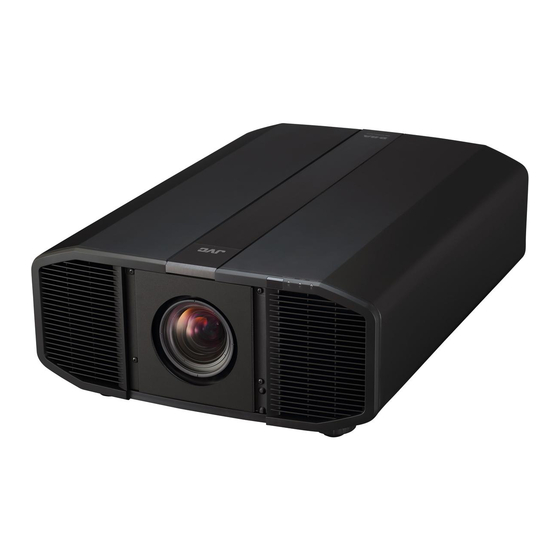
Summary of Contents for JVC BLUEscent DLA-VS47NV
- Page 1 INSTRUCTIONS D-ILA Projector DLA-VS47NV DLA-VS45NV DISPLAYPORT INPUT 1 INPUT 2 DUAL INPUT 3 INPUT 4 QUAD LENS C.M.D. MOTION CONTROL ENHANCE NAME NATURAL DYNAMIC EDIT USER1 USER2 USER3 USER4 USER5 USER6 COLOR LENS PIC. GAMMA TEMP. ADJ. B5A-2671-22...
-
Page 2: Safety Precautions
THIS APPARATUS MUST BE EARTHED. CAUTION: CAUTION: Changes or modification not approved by JVC could To reduce the risk of electric shock, do not remove void the user’s authority to operate the equipment. cover. Refer servicing to qualified service personnel. - Page 3 IMPORTANT SAFEGUARDS 150 mm and above Electrical energy can perform many useful functions. This unit has been engineered and manufactured to assure your personal safety. But IMPROPER USE 300 mm 300 mm CAN RESULT IN POTENTIAL ELECTRICAL and above and above SHOCK OR FIRE HAZARD.
- Page 4 If installation is performed by an authorized JVC service center. unqualified person, it may cause personal injury or When fixing the unit to the ceiling, Please note that we do electrical shock.
- Page 5 POWER CONNECTION IMPORTANT (Europe only): For USA and Canada only Use only the following power cord. The wires in the mains lead on this product are Power cord colored in accordance with the following cord: : Earth Green-and-yellow Blue : Neutral Brown : Live As these colors may not correspond with the...
- Page 6 ENGLISH Information for Users on Disposal of Old Equipment and Batteries [European Union only] These symbols indicate that equipment with these symbols should not be disposed of as general household waste. If you want to dispose of the product or battery, please consider the collection systems or facilities for appropriate recycling.
- Page 7 For the customers In the U.S.A. and Canada CAUTION Use of controls or adjustments or performance of LASER RADIATION RAYONNEMENT LASER AVOID DIRECT EYE EVITER L’EXPOSITION EXPOSURE DIRECTE DES YEUX procedures other than those specified herein may result CLASS 3R LASER PRODUCT PRODUIT LASER DE CLASSE 3R WAVE LENGTH : 453nm LONGUEUR D'ONDE : 453nm...
- Page 8 For the customers In other countries CLASS 1 LASER PRODUCT LASER CAUTION LABEL WARNING Do not look into the lens while in use. CAUTION Use of controls or adjustments or performance of procedures other than those specified herein may result in hazardous radiation exposure.
- Page 9 For the customers In China...
-
Page 10: Table Of Contents
Contents Getting Started Maintenance Safety Precautions ..........2 Maintaining the Cabinet and Remote Control ..48 Accessories/Optional Accessories ......11 Cleaning and Replacing the Filter ......48 Check the Accessories ........11 Long term storage of projector ......49 Controls and Features ........... 12 About the Lens ............ -
Page 11: Accessories/Optional Accessories
Accessories/Optional Accessories Check the Accessories Remote control ............... 1 piece AAA-size batteries (for operational check) ......2 pieces Power cord (for USA) (about. 2 m) ......... 1 piece Power cord (for EU) (about 2 m) ..........1 piece Lens spacer ................1 piece Screw ................... -
Page 12: Controls And Features
Controls and Features Main Unit - Front A Lens (sold separately) C Indicator Zoom lens or short focal length lens is optional. Refer to “Indicator Display on the Main Unit”P. 69. B Remote Sensor (front) D Exhaust vent Please aim the remote control at this area when using Warm air is discharged to cool down the internal temperature. -
Page 13: Main Unit - Rear
Main Unit - Rear F Input terminals I Power input terminal For details on the terminals, refer to “Main Unit - Input Connect the supplied power cord to this terminal. Terminals”P. 14. J Air Inlets G Operation panel The inlets take in air to cool down the internal For more details, please refer to the “Operation temperature. -
Page 14: Main Unit - Input Terminals
Main Unit - Input Terminals Enlarged View of Rear Face A [SYNC OUT] terminal E [DisplayPort 1] input terminal For synchronizing with other equipment. F [DisplayPort 2] input terminal B [SERVICE] terminal G [DisplayPort 3] input terminal For updating the software using a commercially available USB flash drive. -
Page 15: Remote Control
Remote Control A B [STANDBY] M [PICTURE MODE] Switches the picture mode. (P. 28) Turns off the power. (P. 25) Press [NATURAL], [DYNAMIC] or B C [ON] [USER1] to [USER6] to switch to the Turns on the power. (P. 24) respective picture mode. -
Page 16: Loading Batteries Into The Remote Control
Loading Batteries into the Remote Control If the remote control has to be brought closer to the unit Loading the batteries to operate, it means that the batteries are wearing out. Replace the batteries with new ones (AAA). Insert the batteries according to the t s marks. Be sure to insert the s end first. -
Page 17: Menu
Menu Select the icon at the top of the menu to display its corresponding setting item as shown below. A Picture Adjust B Input Signal C Installation D Display Setup E Function F Information... -
Page 18: Installing The Projector
Installing the Projector Precautions during Installation Please read the following carefully before installing this Maintain clearance from the wall, etc. unit. As the unit discharges a large amount of heat, install it with adequate clearance from the surroundings as shown When carrying this unit below. -
Page 19: Precautions During Mounting
Precautions during Mounting When this unit is to be mounted to a fixed position for Securing (mounting) the projector use, install it horizontally. Make sure to secure the main unit to prevent accidents such as during an earthquake. Securing the projector (directly mount) For directly mounting projectors to a stand for motion or non-motion systems, remove the four feet from the base of the projector and use the inner six mounting screw holes (see pictures below). - Page 20 Take the necessary actions to prevent the main unit from falling off such as during an earthquake. Regardless of the warranty period, JVC is not liable for any product damage caused by mounting the unit with non-JVC ceiling fittings or to an environment that is not Rear suited for ceiling mount.
-
Page 21: Adjusting The Position
Adjusting the Position Adjusting the elevation angle of the projector 4 Locations The height and inclination of the unit (0 to 5 mm) can be adjusted by turning the feet. Lift the unit and adjust the four feet. Extend Contract Feet... -
Page 22: Connecting The Projector
Connecting the Projector Do not turn on the power until connection is complete. The connection procedures differ according to the device used. For details, please refer to the instruction manual of the device to be connected. This projector is used for projecting images. To output the audio of connected devices, please connect a separate audio output device, such as an amplifier or speaker. -
Page 23: Connecting To The Rs-232C Terminal
Connecting to the RS-232C Terminal This Unit Laptop, etc. To [RS-232C] Terminal RS-232C Terminal RS-232C Connection Cable (Sold Separately) For more information on control, please refer to “External Control”P. 57. Connecting to the REMOTE Terminal This Unit To [REMOTE] Terminal Wired Remote Controller (Sold Separately) Connection Cable... -
Page 24: Viewing Videos
Viewing Videos MEMO Connect the power cord, and ensure that the “STANDBY/ON” indicator lights up in red. Turn on the power Remote control: press the C [ON] button Projector unit: press the A button “STANDBY/ON” lights up (red) “STANDBY/ON” lights up (green) In standby state During startup Remote Control... - Page 25 Turn off the power Remote control: press the B [STANDBY] button Projector unit: press the A button While the “Are you sure you want to turn off?” message is displayed, press the button again. The laser light source and IR light source turn off, and the “STANDBY/ON” indicator switches from a green light to a red blinking light.
-
Page 26: Adjustments And Settings In The Menu
Adjustments and Settings in the Menu Pressing the [MENU] button displays the menu. Press the [JKH I] keys to select an item, followed by pressing the [OK] button to confirm the selection. List of Menu Items Picture Adjust Picture Mode ..............................P. 28 9 Sharpness .............................. - Page 27 Installation Lens Control ..............................P. 36 9 Focus ................................. P. 36 9 Zoom ................................P. 36 9 Shift ................................P. 36 9 Image Pattern ............................. P. 36 Pixel Adjust ..............................P. 37 9 Adjust ................................. P. 37 9 Adjust Area ..............................P. 37 9 Adjust Color ..............................
-
Page 28: Picture Adjust
Picture Adjust Picture Mode You can adjust the image quality according to the type of video image you are viewing. Setting Description Natural Image quality that focuses on natural color and gradation reproduction. Suitable for displaying video images in general. Dynamic This is the picture setting best suited for viewing the picture in a room that cannot be made completely dark. -
Page 29: Color Management
Color Management Each of the colors is adjustable according to the user’s preference. Select the “Picture Adjust” " “Color Management” menu, and press the [OK] button. Set “Color Management” to “On”, and press the [OK] button Adjust to the preferred color A Select “Color Selection”, and press the H I keys to select the color to adjust Axis Position (Image) -
Page 30: Color Temp
Color Temp. For setting the color temperature of the video image. The selectable “Color Temp.” settings vary according to “Picture Mode”. “Color Temp.” Color Temp. Description 5500K Increasing the value enhances the blue tone of the video image, while decreasing the value enhances the red tone. -
Page 31: Gamma
Gamma You can adjust the output value of the projected image with respect to the video signal input. “Gamma” Gamma Description The gamma is set to “2.2”. Custom 1 to Custom 3 Enables fine adjustment of gamma according to preference. You can perform fine adjustments based on the selected gamma adjustment setting. -
Page 32: I Display Mode
Display Mode For managing the e-shift status v and the lighting condition of the light sources. Setting Description Normal Only the laser light source lights up. Only the IR light source lights up. e-shift v This is the mode for displaying e-shift. Only the laser light source lights up. NV(e-shift) v This is the mode for displaying e-shift. -
Page 33: Light Source Ctrl
Light Source Ctrl For switching the function to automatically control the current of the laser light source. Setting Description Manual For configuring the current setting manually. Auto Intensity Controls the current automatically to maintain the brightness at a constant level. FEDLC Detects the current information that is included in the input image and controls the current automatically. -
Page 34: Blur Reduction
Blur Reduction For reducing the after-image, which occurs in a fast-moving scene. Blur Reduction is grayed out and cannot be adjusted when “Display Mode” is set to “NV(FS)”, “NV(e-shift FS)” or “3D” and when an out of range signal is input. Clear Motion Drive For reducing the after-image, which occurs in a fast-moving scene. -
Page 35: Input Signal
Input Signal Input Level For setting the dynamic range (gradation) of the video input. If the dynamic range is not appropriate, the bright areas become overexposed, and the dark areas become underexposed. Setting Description 16-235 (Video) Select this setting if you are inputting video signals (dynamic range: 16 - 235). 0-255 (PC) Select this setting if you are inputting PC signals (dynamic range: 0 - 255). -
Page 36: Installation
Installation Lens Control Focus / Zoom / Shift For adjusting the lens according to the projection position MEMO To use the Shift function, a motorized lens shift unit is required. For details on installing the motorized lens shift unit (sold separately), refer to the instruction manual of the motorized lens shift unit. Motorized lens shift unit (product no.: PK-MLS01) Press the [LENS CONTROL] button, and use the [JKH I] keys to adjust Focus, Zoom (screen size), and Shift (screen position) -
Page 37: Pixel Adjust
Pixel Adjust For correcting the phase shifting between each RGB color by adjusting the pixel. Adjust For setting the adjustment feature to On or Off. Adjust Area Setting Description Whole Adjusts the entire image. Zone Enables fine adjustment of each area by dividing the screen evenly into 10 vertical and horizontal zones. - Page 38 Whole Adjust (Pixel) Operation Procedure For making general adjustments to slight color fringing in the horizontal/vertical directions of the video image. A Set “Adjust Area” to “Whole” B Select “Adjust Color” and “Adjust Pattern Color” C Select “Adjust (Pixel)”, and press the [OK] button The Adjustment mode is activated, and the selected adjustment pattern and Adjustment (Pixel) window are displayed.
- Page 39 Whole Adjust (Fine) Operation Procedure For making general adjustments on the misalignment of the entire screen using “Adjust (Pixel)”, followed by making fine adjustments. A Set “Adjust Area” to “Whole” B Select “Adjust Color” and “Adjust Pattern Color” C Select Adjust (Fine), and press the [OK] button The Adjustment mode is activated, and the selected adjustment pattern and Fine window are displayed.
- Page 40 Zone Adjust Operation Procedure For fine-tuning misalignments on a part of the screen after adjusting the overall screen misalignment using “Adjust (Pixel)” and “Adjust (Fine)”. The screen can be divided vertically and horizontally into 10 sections for partial adjustments to be made. A Set “Adjust Area”...
-
Page 41: Mask
Mask For hiding the peripheral area of the image with a mask (black strip). Setting Description Not masked. Hides the ranges specified in “Top”, “Bottom”, “Left” and “Right” by masking (with black strips). Mask: black strip around the periphery “Top” / “Bottom” / “Left” / “Right” For specifying the ranges to hide by masking (with black strips). - Page 42 Operation procedure for Adjust A Select “Adjust Pattern Color” B Select “Adjust”, and press the [OK] button The Adjustment mode is activated, and the selected adjustment pattern and Adjustment window are displayed. Distortion Correction Position 0 / 0 Back BACK C Select the position to compensate by using the [JKH I] keys to move the cursor, followed by pressing the [OK] button.
-
Page 43: Edge Blending
Edge Blending Corrects the seam between the images during projection by multiple projectors. * This function is disabled when “Picture Mode” is set to “Dynamic”. Edge Blending For setting the function to On or Off. Setting Description Disables the Edge Blending function. Enables the Edge Blending function. -
Page 44: Display Setup
LED Indication When “LED Indication” is set to “Off”, the LED indicator does not light up or blink under the following status. When the time to replace the laser light source or IR light source is near. (P. 47) When HIDE is on. (P. 69) When the projector receives a signal from a remote control which is set to a different code mode (A or B). -
Page 45: Function
Function Sync Out For selecting the type of signal to output from Sync Out. Setting Description Input (Positive) Outputs a signal that is synchronized with the vertical sync signal of the input video signal. (*1) Input (Negative) Outputs a signal with reversed polarity that is synchronized with the vertical sync signal of the input video signal. -
Page 46: Remote Code
Glossary of Network Terminology DHCP : Abbreviation for Dynamic Host Configuration Protocol. This is a protocol for the network to assign an IP address automatically to the connected device. IP Address : Numeric characters for identifying the device that is connected to the network. Subnet Mask : Numeric characters that define the bit count used for the network address that is a segment of the IP address. -
Page 47: Information
Information Page 1 Setting Description Input Displays video input terminal. Status Displays the image output status. Resolution Displays the resolution information of signal input to each of the DP 1 to DP 4 (DP 1 / DP 2 / DP 3 / DP 4) terminals. -
Page 48: Maintaining The Cabinet And Remote Control
Maintaining the Cabinet and Remote Control Gently wipe off dirt on the cabinet with a soft cloth. If it is extremely dirty, wet a cloth in water, wring dry and use it to wipe off the dirt, followed by wiping again with a dry cloth. -
Page 49: Long Term Storage Of Projector
CAUTION Do not wash the air filter with water. Doing so may cause the filter to deteriorate. Make sure to attach the air filter and sponge filter in the correct sequence. MEMO If the air filter or sponge filter is damaged and requires replacement, or if dust gets into the unit, consult your authorized dealer or nearby service center. -
Page 50: About The Lens
About the Lens This projector does not come with a projection lens. To use the projector, please mount a projection lens according to your requirements. When using an optional standard zoom lens or short focus lens, a spacer and shift plate are required. Use the spacer that comes with this unit. - Page 51 Unscrew the screw using a Phillips screwdriver to remove the front plate Front Plate Secure the lens spacer to the shift plate using the supplied screws Lens Spacer (This part is bundled in the Accessory BOX) Shift Plate Screw×4 (optional) (Please use the screws packed with Lens Spacer) Attach the spacer and insert lens...
- Page 52 Connect the motor cable Connect the motor cable (20pin) to lens. Motor Cable CAUTION Keep the cable away from the motor gear when clamping the motor cable. Tighten the 4 screws using the Phillips head screwdriver to fasten the lens Use the screws that comes with the lens.
-
Page 53: Troubleshooting
Troubleshooting Before sending the unit to your authorized dealer for repair, please check the following points. The following symptoms are not malfunctions. You do not need to worry about the following symptoms if there is no abnormality on the screen. A part of the top or front surface of the unit is hot. - Page 54 3D images do not appear Check Action Refer to Is an intermediate device (AV amplifier, Connect the source device to the projector directly, and — divider, etc.) in use? check whether there is any improvement in the condition. If the condition improves, it is likely that this is not caused by malfunction of the projector.
- Page 55 Projected image is dark Check Action Refer to Is the laser light source near exhaustion? Check the laser light source time in the “Information” menu. P. 47 If 20,000 hours have elapsed, the brightness will be half the brightness at shipment. Is the aperture closed? Increase the value of the “Aperture”...
-
Page 56: When The Following Messages Appear
Zoom or focus does not work Check Action Refer to Is the lens replaced? Depending on the lens position, the lens may not work P. 36 when it has been replaced. While at the Focus / Zoom adjustment screen, press and hold the J or K key for 2 seconds or longer. -
Page 57: External Control
External Control It is possible to control this unit by connecting it to a PC using an RS-232C cross cable (D-sub 9-pin). The projector can be controlled by connecting it to a PC through the computer network with a LAN cable for control commands to be sent to the projector. -
Page 58: Command Format
Command Format The command between this unit and the computer consists of “Header”, “Unit ID”, “Command”, “Data” and “End”. Header (1 byte), Unit ID (2 bytes), Command (2 bytes), Data (n bytes), End (1 byte) Header This binary code indicates the start of communication. Binary Code Type Description... -
Page 59: Remote Control Code
Remote Control Code Binary code is sent during communication. The following applies to the case when the remote control code is “A”. In the case of “B”, add “36” to the beginning of the code. Remote Control Button Name Binary Code Remote Control Button Name Binary Code STAND BY... -
Page 60: Communications Example
Communications Example This section shows the communication examples of RS-232C. Operating command Type Command Description Connection check PC " This unit: 21 89 01 00 00 0A Connection check This unit " PC: 06 89 01 00 00 0A Power (On) PC "... -
Page 61: Specifications
Specifications Product Name D-ILA Projector Model Name DLA-VS47NV, DLA-VS45NV Display Panel/Size D-ILA device *1, 2 0.69” 4K D-ILA (4096 x 2160 pixels) x 3 Light Source Laser diode and IR LED Screen Size Approx. 60” to 300” (Aspect ratio of 4096 x 2160) Brightness 3000 lm (visible light) Projection Distance... - Page 62 Screen Size and Projection Distance GL-MZ4009Z Projection Distance (m) Screen Size 17:9 Screen 16:9 Screen Diagonal (Inch) Wide-end Tele-end Wide-end Tele-end 1.22 1.74 1.29 1.83 1.44 2.04 1.52 2.15 1.65 2.34 1.74 2.47 1.87 2.65 1.97 2.78 2.08 2.95 2.19 3.10 2.30 3.25...
- Page 63 GL-MZ4014Z Projection Distance (m) Screen Size 17:9 Screen 16:9 Screen Diagonal (Inch) Wide-end Tele-end Wide-end Tele-end 1.66 3.43 1.75 3.61 1.96 4.02 2.06 4.23 2.25 4.60 2.37 4.84 2.54 5.19 2.67 5.46 2.83 5.77 2.98 6.07 3.12 6.36 3.28 6.69 3.41 6.94 3.59...
- Page 64 Types of Possible Input Signals Single - DP1 - DP4 Original Input Signal No. of Projector Total No. Total No. No. of dot CLK Effective Designation Resolution Terminal for Resolution fh [kHz] fv [Hz] of Dots of Lines Effective [MHz] Lines Connection [dot]...
- Page 65 Dual - stripes Original Input Signal No. of Projector Total No. Total No. No. of dot CLK Effective Designation Resolution Terminal for Resolution fh [kHz] fv [Hz] of Dots of Lines Effective [MHz] Lines Connection [dot] [line] Dots [dot] [line] WQXGA 2560 x 1600 [DP 1], 1280 x 1600 99.458...
- Page 66 Dual - frame sequential Original Input Signal No. of Projector Total No. Total No. No. of dot CLK Effective Designation Resolution Terminal for Resolution fh [kHz] fv [Hz] of Dots of Lines Effective [MHz] Lines Connection [dot] [line] Dots [dot] [line] WQXGA 2560 x 1600 [DP 1],...
- Page 67 Quad - stripes Original Input Signal No. of Projector Total No. Total No. No. of dot CLK Effective Designation Resolution Terminal for Resolution fh [kHz] fv [Hz] of Dots of Lines Effective [MHz] Lines Connection [dot] [line] Dots [dot] [line] 3840 x 2160 [DP 1], 960 x 2160 135.000 60.000...
- Page 68 Quad - frame sequential Original Input Signal No. of Projector Total No. Total No. No. of dot CLK Effective Designation Resolution Terminal for Resolution fh [kHz] fv [Hz] of Dots of Lines Effective [MHz] Lines Connection [dot] [line] Dots [dot] [line] 3840 x 2160 [DP 1], 1920 x 2160 135.000...
- Page 69 Indicator Display on the Main Unit Meaning of the front panel indicators The indicator lights up. The indicator appears blinking. Operation mode display Displays using the different colors and solid/blinking light of the indicator on the projector unit. “STANDBY/ON” lights up (red) “STANDBY/ON”...
- Page 70 Warning display You can tell the details of a warning from the (repeated) displays of the “WARNING” and “LIGHT” indicators. The “STANDBY/ON” indicator will light up or appear blinking according to the operation mode of the projector unit. (Please refer to ““Operation mode display”P. 69”.) The Warning mode is activated once the message is displayed.
- Page 71 Dimensions (Unit: mm) Top Surface Bottom Surface Front Rear Surface...
-
Page 72: Index
Index Installation Method ..........18 A Accessories ............11 Adjusting Distortion of the Projection Screen ..36 L Lens Control ............36 Adjustment and Setting by the Menu ....26 Aperture ............... 28 M Mask ..............41 Menu Items ............26 B Back Color ............ - Page 74 1120KSY-SW-X © 2018...