Table of Contents
Advertisement
Quick Links
- 1 Chapter 1. Installing an Amcc 3Ware 9550Sx Raid Controller
- 2 Installation Considerations
- 3 9550Sx 8-Port with Standard Sata Connectors
- 4 9550Sx 4-Port with Standard Sata Connectors
- 5 9550Sx 16-Port with Multilane Internal Sata Connectors
- 6 9550Sx 12-Port with Multilane Internal Sata Connectors
- 7 Configure Your Raid Arrays
- Download this manual
Advertisement
Table of Contents

Related Manuals for 3Ware 9550SXU-4LP-SGL


Summary of Contents for 3Ware 9550SXU-4LP-SGL
- Page 1 3ware ® SATA RAID Controller Supports the 9550SX Series PN 720-0124-03 January 2006...
- Page 2 Moffett Park Drive, Sunnyvale, CA 94089. Trademarks 3ware, Escalade, and 3DM are all registered trademarks of AMCC. The 3ware logo, 3BM, StorSwitch, TwinStor, and R5 Fusion are all trademarks of AMCC. All other trademarks herein are property of their respective owners.
-
Page 3: Table Of Contents
Table of Contents Chapter 1. Installing an AMCC 3ware 9550SX RAID Controller 1 Before You Begin ..........1 Contents of Package . - Page 4 Feedback on this manual ........35 3ware 9550SX Serial ATA RAID Controller Quick Install Guide...
-
Page 5: Chapter 1. Installing An Amcc 3Ware 9550Sx Raid Controller
AMCC 3ware 9550SX RAID Controller This document describes the physical installation of the AMCC 3ware 9550SX RAID controllers. It contains the following topics: “Before You Begin” things you should consider before starting installation, and tools and equipment you will need. -
Page 6: Other Documentation
Consider these factors when deciding on the slot in which to insert the controller: Cable routing may be easier if you install the 3ware RAID controller next to an open slot. The amount of clearance you need will depend on the number of drives you will be connecting to the controller. - Page 7 If you are building a system from scratch, you may want to consider using a chassis or drive carrier that is compatible with the 3ware RAID controller activity LEDs, such as the AMCC RDC-400- SATA drive carrier, available through AMCC.
-
Page 8: What You Need: Tools And Equipment
Chapter 1. Installing an AMCC 3ware 9550SX RAID Controller Drive Installation Considerations Selecting an enclosure. 10, or 50, you may want to consider installing drives into hot- swappable enclosures, so that they can be easily removed in the event of a drive failure. -
Page 9: Protecting Equipment And Data
Do not remove the 3ware RAID controller from its protective bag until you are properly grounded. Handle the 3ware RAID controller by its edges or by the black rail and metal bracket at its two ends. Do not touch any pin, contact, lead or component on the 3ware RAID controller. -
Page 10: 9550Sx Raid Controller Cards
Chapter 1. Installing an AMCC 3ware 9550SX RAID Controller 9550SX RAID Controller Cards Serial ATA ports are usually double-stacked connectors. Odd- numbered ports are usually located below even-numbered ports. On the 8-port controller shown below, ports 6 and 7 are both on top. -
Page 11: 9550Sx 4-Port With Standard Sata Connectors
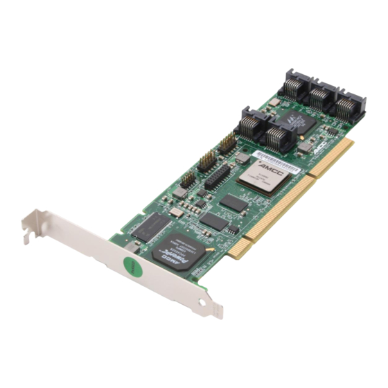
9550SX 4-Port with Standard SATA Connectors Figure 2. 4-Port 3ware 9550SX-4LP Serial ATA RAID Controller C connector Slots for battery holder 9550SX 12-Port with Standard SATA Connectors Figure 3. 12-Port 3ware 9550SX-12 Serial ATA RAID Controller Ports 10 and 11... -
Page 12: 9550Sx 12-Port With Multilane Internal Sata Connectors
Chapter 1. Installing an AMCC 3ware 9550SX RAID Controller 9550SX 12-Port with Multilane Internal SATA Connectors Figure 4. 12-Port 3ware 9550SX-12MI Serial ATA RAID Controller C connector Holes for battery holder connection 9550SX 16-Port with Multilane Internal SATA Connectors Figure 5. 16-Port 3ware 9550SX-16ML Serial ATA RAID Controller... -
Page 13: Installing A Serial Ata Raid Controller
To connect SATA cables to the controller If you have a multilane controller, turn to page 13. Note: Take out the SATA cables provided with the 3ware SATA RAID controller. One edge of each SATA cable connector is keyed so that it can only be inserted in one direction. -
Page 14: To Install The Controller In The Computer
4.) Open the computer case according to the manufacturer’s instructions. Find the PCI or PCI-X slot you want to use for the serial 3ware RAID controller. For a discussion of which slot to use, see “Selecting the Slot in Which to Install the Controller”... - Page 15 Save this screw; it will be used to secure the serial 3ware RAID controller after you have seated it in the slot. Position the card in the slot so that the contacts will mate with the grooves in the slot, and all pins make proper contact with the PCI slot pins when pushed into place.
-
Page 16: To Connect The Sata Cables To The Drives
For each drive, select the end of an SATA cable not connected to the 3ware RAID Controller and plug it into the drive or drive carrier. One edge of each SATA cable connector is keyed to ensure proper installation. -
Page 17: Installing A 9550Sx Raid Controller With Multilane Internal Connectors
With a backplane that has individual SATA connectors or individual serial ATA drives, use the multilane break-out cable, which has an SFF-8470 multilane connector on one end, and 4 individual SATA connectors on the other end (see Figure 10). Figure 10. Multilane Serial ATA Break-out Cable (SFF-8470) www.3ware.com... -
Page 18: 9550Sx-16Ml
Chapter 1. Installing an AMCC 3ware 9550SX RAID Controller 9550SX-16ML With a multilane-enabled drive backplane that has the SFF-8087 mini SAS 4i connectors, use the double-ended 4x cable, which has multilane connectors on each end (see Figure 11). Figure 11. Multilane Cable Serial ATA (SFF-8087) -
Page 19: Computer
When the cable is inserted correctly, you will feel it click into place. Figure 13. Connecting an InfiniBand Multilane Cable with an SFF-8470 Connector to the 9550SX-12MI Controller Figure 14. Connecting a Multilane Cable with an SFF-8087 Connector to the 9550SX-16ML Controller www.3ware.com... -
Page 20: To Install The Drives
Chapter 1. Installing an AMCC 3ware 9550SX RAID Controller Insert the controller into the computer. For details, see “To install the controller in the computer” on page 10. If your enclosure has a backplane, connect the other end of each multilane cable to the backplane. -
Page 21: Connecting Drive Activity Led Indicators
Connecting Drive Activity LED Indicators Figure 15, 10, and 11 show the location of LED indicators on the different 9550SX controllers. Figure 15. 8-Port 3ware 9550SX-8LP Serial ATA RAID Controller LED indicators for individual drives on J7 and J8 LED connector details... - Page 22 Chapter 1. Installing an AMCC 3ware 9550SX RAID Controller The LED headers on the 9550SX-12 and the 9550SX-12MI Note: are in a very similar place. Figure 17. 12-Port 3ware 9550SX-12 Serial ATA RAID Controller LED indicators for individual drives J7 is for drives 0, 1, 2, 3 (left to right)
-
Page 23: Additional Details About The Led Status Connectors
Figure 18. 16-Port 3ware 9550SX-16ML Serial ATA RAID Controller LED indicators for individual drives J7 is for drives 0, 1, 2, 3 (left to right) J8 is for drives 4, 5, 6, 7 (left to right) J9 is for drives 8, 9, 10, 11 (left to right) - Page 24 Chapter 1. Installing an AMCC 3ware 9550SX RAID Controller Table 1 summarizes the LED indicator pin positions for the different controllers. If using a chassis that has a common or shared LED Warning: ground, be sure to only connect LED cables to the anode pins on the controller.
-
Page 25: Finishing Up
Close the case and reconnect the power cables. Configure your RAID Arrays Turn to “Configuring Units” in 3ware 9550SX Serial ATA RAID Controller User Guide for information about configuring RAID arrays. - Page 26 Chapter 1. Installing an AMCC 3ware 9550SX RAID Controller 3ware 9550SX Serial ATA RAID Controller Quick Install Guide...
-
Page 27: Chapter 2. Installing The Battery Backup Unit
Battery Backup Unit The Battery Backup Unit (BBU) is an add-on that can be attached to a 3ware 9550SX RAID controller to supply power to the memory module from an attached battery pack in the event of a system power loss. This allows the controller to use write-caching for optimal performance and not be exposed to data loss in the event of a system power failure. -
Page 28: Tools And Equipment Required
Connector on the BBU mates to receptacle on the controller. Post on the BBU mates to post hole on the controller. a) Clips Figure 19. Points of connection on the BBU 3ware 9550SX Serial ATA RAID Controller Quick Install Guide c) Post b) BBU connector... - Page 29 Slots for the clips b) BBU receptacle c) Hole for post Figure 20. Points of connection on the half-height controller b) BBU receptacle c) Hole for post a) Holes for the clips Figure 21. Points of connection on the full-height controller www.3ware.com...
-
Page 30: Installation Instructions
Mate the connector on the BBU control module with the receptacle on the controller. Match the plastic post on the BBU with the hole on the controller. Figure 23. BBU control module ready to connect to the controller 3ware 9550SX Serial ATA RAID Controller Quick Install Guide... - Page 31 When the plastic post and the connector are attached correctly, the module is in the correct orientation. www.3ware.com To avoid possible damage to the controller Installation Instructions...
- Page 32 Press down gently on the top of the battery unit so that the battery holder flexes slightly and the clip on the bottom slips over the slot on the bottom edge of the controller. 3ware 9550SX Serial ATA RAID Controller Quick Install Guide...
- Page 33 If you have a 12-port or 16-port 9550SX: Insert the clips on the top of the battery module into the holes on the controller. Figure 28. Attaching the battery module to the full-height controller www.3ware.com Installation Instructions...
- Page 34 Figure 29. Battery power connector inserted in power receptacle The controller is now ready to install in your system. Figure 23 shows the BBU fully installed on 3ware controllers. 3ware 9550SX Serial ATA RAID Controller Quick Install Guide The battery will drain if it is plugged in and...
- Page 35 Installation Instructions Figure 30. BBU installed on controllers www.3ware.com...
-
Page 36: Replacing The Battery
You can check the current status of the battery, and test it. For details, see instructions in 3ware 9550SX Serial ATA RAID Controller User Guide. There is a risk of explosion if the battery is Caution: replaced by an incorrect type. - Page 37 To do so, press down on the lever-like clip on the battery power connector and slide it out of the slot. (If desired, you can remove the BBU control module to facilitate disconnecting the power cable.) www.3ware.com Replacing the Battery a) Push the battery module down gently.
- Page 38 You can run the battery test from the BBU page of either 3BM or 3DM 2, or by using the 3ware CLI. For detailed instructions, see the 3ware 9550SX Serial ATA RAID Controller User Guide and the 3ware 9000 Series Serial ATA RAID Controller CLI Guide.
-
Page 39: Sales And Ordering Information
Appendix: Technical Support For support, troubleshooting tips, frequently asked questions, software releases, and compatibility information related to 3ware RAID controllers, refer to: 3ware support page at: http://www.3ware.com/support/ 3ware knowledgebase: http://www.3ware.com/KB/kb.asp 3ware software downloads: http://www.3ware.com/support/download.asp 3ware documentation: fhttp://www.3ware.com/support/userdocs.asp 3ware Compatibility Lists: http://www.3ware.com/support/sys_compatibility.asp... - Page 40 Appendix: Technical Support 3ware 9550SX Serial ATA RAID Controller Quick Install Guide...