Table of Contents
Advertisement
Advertisement
Table of Contents

Related Manuals for 3Ware 9650SE-8LPML-SGL


Summary of Contents for 3Ware 9650SE-8LPML-SGL
- Page 1 ® 3ware 9650SE Serial ATA RAID Controller PN 720-0158-00 March 2007...
- Page 2 Trademarks 3ware®, Escalade®, 3DM®, and TwinStor® are all registered trademarks of AMCC. The 3ware logo, 3BM, Multi-Lane, StorSave, StorSwitch, StreamFusion, and R5 Fusion are all trademarks of AMCC.
-
Page 3: Table Of Contents
Safety Information ......... . 10 Chapter 2. Installing Your 3ware RAID Controller ..15 Tools You Need . -
Page 4: About This Guide
3ware HTML Bookshelf is an HTML version of the documentation, combining the User Guide and the CLI Guide. Online help is also available when you are using 3DM 2 (3ware Disk Manager). Additional support information is available in the 3ware... -
Page 5: Chapter 1. Getting Started
9650SE-2LP.) RAID levels 0, 1, 5, 6, 10, 50, Single Disk, JBOD, and Hot Spare (RAID 6 and RAID 50 are available only with 3ware RAID controller models that have 8 or more ports) PCI Express®... -
Page 6: System Requirements
(“direct attach”) or with individual drives can be purchased separately. For more about these cables see “Multi-lane M8 fanout cable” on page 9. If you purchased the 3ware RAID controller in a single pack or as part of a bulk pack, cables are not included. System Requirements... - Page 7 9650SE-12LPML 9650SE-16LPML 9650SE-24M8 Drive Requirements Depending on the particular model, the 3ware RAID controller may be connected to up to twenty-four SATA drives using the supplied interface cables. Drives must meet SATA-1 (1.5 Gb/s) or SATA-2 (3.0 Gb/s) standards. Drives may be of any capacity or physical form factor.
-
Page 8: 9650Se Raid Controller Card Models
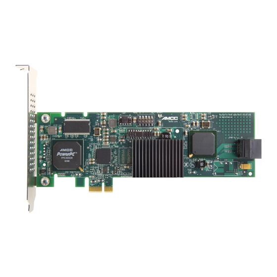
For best viewing, screen resolution should be 1024 x 768 or greater, with 16-bit color or greater. 9650SE RAID Controller Card Models Figure 1. 2-Port 3ware 9650SE-2LP Serial ATA RAID Controller 3ware 9650SE Serial ATA RAID Controller Installation Guide Heat Sink... - Page 9 Figure 2. 4-Port 3ware 9650SE-4LPML Serial ATA RAID Controller C connector Slots for battery holder Figure 3. 8-Port 3ware 9650SE-8LPML Serial ATA RAID Controller C connector Slots for battery www.3ware.com 9650SE RAID Controller Card Models LED Connector Heat Sink BBU connector and hole for post...
- Page 10 Chapter 1. Getting Started Figure 4. 12-Port 3ware 9650SE-12ML Serial ATA RAID Controller C connector Holes for battery holder Figure 5. 16-Port 3ware 9650SE-16ML Serial ATA RAID Controller C connector Holes for battery holder 3ware 9650SE Serial ATA RAID Controller Installation Guide...
-
Page 11: Cables
The 2-port 9650SE RAID controller uses standard SATA cables. Multi-lane Cables Important: with your 3ware RAID controller. Using an incorrect cable can result in drives that are not detected. The appropriate cables are included with your controller. If you must replace a cable, see the list of available cables and associated part numbers at http://3ware.com/products/cables.asp. - Page 12 ATA drives, Multi-lane breakout cables have an SFF-8087 Multi-lane connector on one end and four individual SATA connectors on the other end (Figure 7). This is the type of cable that ships with most 3ware Note: 9650SE Multi-lane controllers (except the 24-port). Depending...
- Page 13 M8 connector on one end and eight individual SATA connectors on the other end. They look similar to the Multi-lane serial breakout cable shown in Figure 7, except that they have eight individual connectors instead of four. www.3ware.com...
-
Page 14: Safety Information
Chapter 1. Getting Started Multi-lane converter cables for 4-port, 8-port, 12-port, and 16-port controllers To connect from a 3ware 9650SE multi-lane RAID controller to a chassis that has SFF-8470 connectors on the backplane, use multi-lane converter cables, which have a SFF-8087 connector on one end and an Infini-band SFF-8470 connector on the other (Figure 10). -
Page 15: Protecting Equipment And Data
Protecting Equipment and Data Heat Sink Warning. sink shipped with the 3ware 9650SE RAID controller. Replacing the heat sink will alter thermal characteristics and cooling requirements and may cause the controller to fail. Replacing the factory-installed heat sink will void the warranty. -
Page 16: Installation Considerations
Do not remove the 3ware RAID controller from its protective bag until you are properly grounded. Handle the 3ware RAID controller by its edges or by the black rail and metal bracket at its two ends. Do not touch any pin, contact, lead or component on the 3ware RAID controller. - Page 17 If you are building a system from scratch, you may want to consider using a chassis or drive carrier that is compatible with the 3ware RAID controller activity LEDs, such as the AMCC RDC-400- SATA drive carrier, available through AMCC.
- Page 18 Things to Watch Out For During Installation of the RAID Controller Be careful when installing the 3ware RAID controller into your system. Excessive force can damage the board or your system. Be sure to follow the installation instructions in “Chapter 2.
-
Page 19: Chapter 2. Installing Your 3Ware Raid Controller
An ESD grounding strap or mat A Phillips screwdriver Before You Start 3ware 9650SE RAID controllers can be installed in a standard enclosure or in an enclosure with a backplane. Be sure to read “Safety Information” on page 10 in Chapter 1. -
Page 20: Step 1 (9650Se-2Lp). Connect The Cables To The Controller
Repeat steps 2 and 3 for the second SATA cable. (You connect one cable for each hard drive you will attach.) 3ware 9650SE Serial ATA RAID Controller Installation Guide Port 0 is on top. Port 1 is on the bottom... -
Page 21: Step 1 (Multi-Lane Controllers). Connect The Cables To The Controller
Connecting a Multi-lane Cable with an SFF-8087 Connector to the 9650SE-16ML Controller Depending on the which model of the 9650SE you have, and the number of drives you will be connecting, you will connect between one and four multi-lane cables. www.3ware.com... -
Page 22: Step 2. Install The Controller In The Computer
10.) Open the computer case according to the manufacturer’s instructions. Find the PCI Express slot you want to use for the 3ware 9650SE RAID controller. For a discussion of which slot to use, see “Selecting the Slot in Which to Install the Controller”... - Page 23 Press down gently on the edge of the 3ware RAID controller directly above the PCI Express slot until it is fully seated. Figure 13. Inserting Controller Into PCI Express Slot Do NOT use a PCI or PCI-X slot. Check that the 3ware RAID controller’s metal bracket covers the hole in the case and secure the bracket with the screw that was used to secure the filler bracket in step 5.
-
Page 24: Step 3. Connect The Cables To The Drives
(Optional) Connect the drive activity LED connectors. For details, turn to “Step 4. Connecting Drive Activity LED Indicators (Optional)” on page 21. Turn to “Step 5. Finishing Up the RAID Controller Installation” on page 28. 3ware 9650SE Serial ATA RAID Controller Installation Guide... -
Page 25: Step 3. Connect Cables To The Sata/Sas Drive Multi-Lane Backplane
“Deciding Whether to Use the LED Status Connector” on page 13. Figure 15 through Figure 20 show the location of LED indicators on the different 9650SE controllers. Additional detail about these connectors starts on page 25. www.3ware.com... - Page 26 Chapter 2. Installing Your 3ware RAID Controller Figure 15. 2-Port 3ware 9650SE-2LP Serial ATA RAID Controller LED indicators for individual drives on J7: 0 and 1 (left to right) Figure 16. 4-Port 3ware 9650SE-4LPML Serial ATA RAID Controller LED indicators for individual...
- Page 27 Step 4. Connecting Drive Activity LED Indicators (Optional) Figure 17. 8-Port 3ware 9650SE-8LPML Serial ATA RAID Controller LED indicators for individual drives J7 is for drives 0, 1, 2, 3 (left to right) J8 is for drives 4, 5, 6, 7 (left to right) Figure 18.
- Page 28 Chapter 2. Installing Your 3ware RAID Controller Figure 19. 16-Port 3ware 9650SE-16ML Serial ATA RAID Controller LED indicators for individual drives J7 is for drives 0, 1, 2, 3 (left to right) J8 is for drives 4, 5, 6, 7 (left to right)
- Page 29 Step 4. Connecting Drive Activity LED Indicators (Optional) Figure 20. 24-Port 3ware 9650SE-24M8 Serial ATA RAID Controller LED indicators for individual drives J9 is for drives 0, 1, 2, 3 (left to right) J10 is for drives 4, 5, 6, 7 (left to right)
- Page 30 Table 2: LED Indicator Pin Positions Controller Header 9650SE-2LP 9650SE-4LPML J7 9650SE-8LPML J7 9650SE-12ML 3ware 9650SE Serial ATA RAID Controller Installation Guide Pin Pair Orientation Horizontal : : : : : Port number/All 0 1 : : All (all activity indicator)
- Page 31 Step 4. Connecting Drive Activity LED Indicators (Optional) Table 2: LED Indicator Pin Positions Controller Header 9650SE-16ML 9650SE-24M8 www.3ware.com Pin Pair Orientation Horizontal : : : : : Port number/All (All activity 0 1 2 3 All indicator) Orientation Horizontal...
-
Page 32: Step 5. Finishing Up The Raid Controller Installation
3ware Serial ATA RAID Controller User Guide for information about configuring RAID arrays. The user guide is included on the 3ware CD that came with your controller. It is also available from the 3ware website at http://3ware.com/support/userdocs.asp. 3ware 9650SE Serial ATA RAID Controller Installation Guide... -
Page 33: Chapter 3. Installing The Battery Backup Unit
Battery Backup Unit The Battery Backup Unit (BBU) is an add-on that can be attached to a 3ware 9650SE RAID controller to supply power to the memory module from an attached battery pack in the event of a system power loss. This allows the controller to use write-caching for optimal performance and not be exposed to data loss in the event of a system power failure. -
Page 34: Tools And Equipment Required
Connector on the BBU mates to receptacle on the controller. Post on the BBU mates to post hole on the controller. Figure 21. Points of connection on the BBU <> a) Clips 3ware 9650SE Serial ATA RAID Controller Installation Guide c) Post b) BBU connector... - Page 35 Figure 22. Points of connection on the half-height controller a) Slots for the clips b) BBU receptacle c) Hole for post Figure 23. Points of connection on the full-height controller a) Hole and slots for the clips c) Hole for post b) BBU receptacle www.3ware.com...
-
Page 36: Installation Instructions
Mate the connector on the BBU control module with the receptacle on the controller. Match the plastic post on the BBU with the hole on the controller. Figure 25. BBU control module ready to connect to the controller 3ware 9650SE Serial ATA RAID Controller Installation Guide... - Page 37 When the plastic post and the connector are attached correctly, the module is in the correct orientation. www.3ware.com To avoid possible damage to the controller and Installation Instructions...
- Page 38 Figure 27. Clips on the battery module hook over slots on the top edge of the half-height controller Figure 28. Attaching the battery module to the half-height controller 3ware 9650SE Serial ATA RAID Controller Installation Guide...
- Page 39 Insert the clips on the top of the battery module into the holes on the controller. Figure 30. Attaching the battery module to the full-height controller Press down gently on the battery module until the bottom clip snaps into place in the lower hole. www.3ware.com Installation Instructions...
- Page 40 If the system will not be used right away, wait to do this step until the system is ready for use. Figure 31. Battery power connector inserted in power receptacle The controller is now ready to install in your system. 3ware 9650SE Serial ATA RAID Controller Installation Guide...
-
Page 41: Replacing The Battery
You can check the current status of the battery, and test it. For details, see instructions in 3ware Serial ATA RAID Controller User Guide. Caution: There is a risk of explosion if the battery is replaced by an incorrect type. - Page 42 (If desired, you can remove the BBU control module to facilitate disconnecting the power cable.) 3ware 9650SE Serial ATA RAID Controller Installation Guide a) Push the battery module down gently. b) Lift out the bottom...
- Page 43 You can run the battery test from the BBU page of either 3BM or 3DM 2, or by using the 3ware CLI. For detailed instructions, see the 3ware Serial ATA RAID Controller User Guide and the 3ware Serial ATA RAID Controller CLI Guide.
-
Page 44: Appendix: Technical Support
Appendix: Technical Support For support, troubleshooting tips, frequently asked questions, software releases, and compatibility information related to 3ware RAID controllers, refer to: 3ware support page at: http://www.3ware.com/support/ 3ware knowledgebase: http://www.3ware.com/KB/kb.asp 3ware software downloads: http://www.3ware.com/support/download.asp 3ware documentation: http://www.3ware.com/support/userdocs.asp 3ware Compatibility Lists: http://www.3ware.com/products/sys_compatibility.asp...