Table of Contents

Related Manuals for 3Com SuperStack 3 3C17204


Summary of Contents for 3Com SuperStack 3 3C17204
-
Page 1: Getting Started Guide
SuperStack Switch 4400 Family Getting Started Guide Switch 4400 (3C17203) Switch 4400 (3C17204) Switch 4400 PWR (3C17205) Switch 4400 SE (3C17206) Switch 4400 FX (3C17210) http://www.3com.com/ Part No. DUA1720-3AAA09 Published July 2005 ®... - Page 2 3Com Corporation reserves the right to revise this documentation and to make changes in content from time MA 01752-3064 to time without obligation on the part of 3Com Corporation to provide notification of such revision or change. 3Com Corporation provides this documentation without warranty, term, or condition of any kind, either implied or expressed, including, but not limited to, the implied warranties, terms or conditions of merchantability, satisfactory quality, and fitness for a particular purpose.
-
Page 3: Table Of Contents
ONTENTS BOUT UIDE Before You Start Release Notes About Your CD-ROM Conventions Related Documentation Accessing Online Documentation Documentation Comments NTRODUCING THE UPER TACK WITCH About the Switch 4400 Summary of Hardware Features Switch 4400 — Front View Detail 10BASE-T/ 100BASE-TX Ports 100BASE-FX Ports LEDs Switch 4400 —... - Page 4 Manually Configuring IP Information Connecting to a Front Panel Port Connecting to the Console Port Viewing Automatically Configured IP Information Using 3Com Network Director Connecting to the Console Port Methods of Managing a Switch Command Line Interface Management Command Line Interface Management using SSH...
- Page 5 ROBLEM OLVING Solving Problems Indicated by LEDs Solving Hardware Problems Solving Communication Problems Solving Software Upgrade Problems AFETY NFORMATION Power Cord Set — Japan Important Safety Information L’information de Sécurité Importante Wichtige Sicherheitsinformationen Información de seguridad importante Importanti Informazioni di Sicurezza Ważne informacje o zabezpieczeniach OUTS Null Modem Cable...
- Page 6 NDEX EGULATORY OTICES...
-
Page 7: About This Guide
This guide provides all the information you need to install and use the following switches in their default state: ■ ■ ■ ■ ■ All procedures described in this guide apply to all models except where stated. The guide is intended for use by network administrators who are responsible for installing and setting up network equipment;... -
Page 8: About Your Cd-Rom
About Your CD-ROM The CD-ROM contains the following: ■ ■ Most user guides and release notes are available in Adobe Acrobat Reader Portable Document Format (PDF) or HTML on the 3Com World Wide Web site: http://www.3com.com/ Conventions Table 1 Table 1 Notice Icons... -
Page 9: Related Documentation
Table 2 Text Conventions (continued) Convention Keyboard key names If you must press two or more keys simultaneously, the key Words in italics Related In addition to this guide, each Switch documentation set includes the Documentation following: ■ ■ ■ Description names are linked with a plus sign (+). -
Page 10: Accessing Online Documentation
Release Notes are supplied in PDF format on the CD-ROM that accompanies the Switch. The latest release notes are available in Adobe Acrobat Reader Portable Document Format (PDF) on the 3Com World Wide Web site: http://www.3com.com/ Documentation accompanying the Advanced Redundant Power system. - Page 11 SuperStack 3 Switch 4400 Family Getting Started Guide Page 21 Please note that we can only respond to comments and questions about 3Com product documentation at this e-mail address. Questions related to technical support or sales should be directed in the first instance to your network supplier.
- Page 12 BOUT UIDE...
-
Page 13: Introducing The Super Stack 3 Switch
NTRODUCING THE UPER This chapter contains introductory information about the Switch 4400 and how it can be used in your network. It covers summaries of hardware and software features and also the following topics: About the Switch 4400 ■ Switch 4400 — Front View Detail ■... -
Page 14: About The Switch 4400
1: I HAPTER NTRODUCING THE About the Switch The Switch 4400 is a stackable 10/100 Mbps Ethernet switch and 4400 provides high-performance workgroups with a backbone to server connection. The Switch 4400 allows Cascade, Gigabit Ethernet or Fast Ethernet Fiber connections when expansion modules are installed in the expansion slots on the rear of the unit. -
Page 15: Switch 4400 - Front View Detail
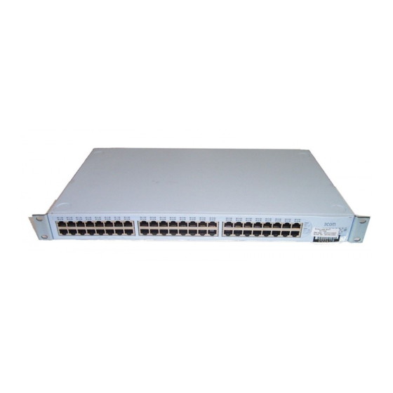
Switch 4400 — Figure 1 Switch 4400 FX — front view Front View Detail Figure 2 Switch 4400 (24-port) / Switch 4400 SE — front view Port LEDs (Packet and Status) 10BASE-T / 100BASE-TX RJ-45 Ports Figure 3 Switch 4400 PWR — front view Status Green = 100Mbps Packet -... -
Page 16: 10Base-T/ 100Base-Tx Ports
1: I 4400 HAPTER NTRODUCING THE UPER TACK WITCH Figure 4 Switch 4400 (48-port) — front view WARNING: RJ-45 Ports. These are shielded RJ-45 data sockets. They cannot be used as standard traditional telephone sockets, or to connect the unit to a traditional PBX or public telephone network. -
Page 17: Leds
connector that allows both the transmit and the receive fibers to be connected in the same space as an RJ-45 port. LEDs Table 4 lists LEDs visible on the front of the Switch, and how to read their status according to color. For information on using the LEDs for problem solving, see “Solving Problems Indicated by LEDs”... - Page 18 1: I HAPTER NTRODUCING THE Port LEDs — Power over Ethernet mode (3C17205 only) Packet Green Status Yellow flashing Power over Ethernet POST error on port. Flash rate is 4 Hz Module LEDs Unit LEDs 1–8 Port LED Status LED (3C17205 only) Power Utilization LEDs (3C17205 only) 4400 UPER...
-
Page 19: Switch 4400 - Rear View Detail
Switch 4400 — Rear Figure 5 Switch 4400 (all models) — rear view View Detail Power Socket The Switch automatically adjusts its power setting to any supply voltage in the range 90-240 VAC. Redundant Power To protect against internal power supply failure, you can use this socket System Socket to connect a Switch 4400 to a SuperStack 3 Advanced Redundant Power System (RPS). -
Page 20: Default Settings
1: I HAPTER NTRODUCING THE Default Settings Table 5 Table 5 Default Settings 4400 UPER TACK WITCH shows the default settings for the Switch 4400: Feature Automatic IP Configuration Port Status Port Speed Duplex Mode Power over Ethernet Flow Control Broadcast Storm Control Virtual LANs (VLANs) Management VLAN... - Page 21 Feature Simple Network Time Protocol (SNTP) SSH v2 Syslog RADA SNMP v1 and v2c SNMP v3 Local Authentication To make Advanced Traffic Prioritization, RADIUS Based Auto QoS Assignment, and Traffic Shaping available on the SuperStack 3 Switch 4400 SE, upgrade the product to the Switch 4400 SE Enhanced Software Upgrade (3C17207).
- Page 22 1: I 4400 HAPTER NTRODUCING THE UPER TACK WITCH...
-
Page 23: Installing The Switch
NSTALLING THE This chapter contains the information you need to install and set up the Switch 4400. It covers the following topics: Package Contents ■ Choosing a Suitable Site ■ Rack-mounting ■ Placing Units On Top of Each Other ■ Stacking Units ■... -
Page 24: Package Contents
Water or moisture cannot enter the case of the Switch. Air flow is not restricted around the Switch or through the vents in the side of the Switch. 3Com recommends that you provide a minimum of 25mm (1in.) clearance. Air temperature around the Switch does not exceed 40 (104 °C... -
Page 25: Rack-Mounting
■ ■ ■ ■ ■ Rack-mounting The Switch 4400 is 1U high and will fit in most standard 19-inch racks. CAUTION: Disconnect all cables from the Switch before continuing. Remove all self adhesive pads from the underside of the Switch if they have been fitted. - Page 26 (not provided). Ensure that ventilation holes are not obstructed. position. The unit information label shows the following: The 3Com product name of the Switch ■ The 3Com 3C number of the Switch ■...
-
Page 27: Placing Units On Top Of Each Other
Placing Units On If the Switch units are free-standing, up to eight units can be placed one Top of Each Other on top of the other. If you are mixing a variety of SuperStack and Hub units, the smaller units must be positioned at the top. If you are placing Switch units one on top of the other, you must use the self-adhesive rubber pads supplied. -
Page 28: Rules For Stacking Units
2: I HAPTER NSTALLING THE Cascade Extender Unit. The Cascade Module is installed into the expansion slot at the rear of the Switch and the Cascade Extender Unit plugs into the Cascade Module. Figure 8 Stacking more than two Switch 4400 units For information on ordering the Cascade Kits contact your supplier. - Page 29 3Com strongly recommends that you upgrade all Switch 4400 units ■ (24-port and 48-port) in a stack to the latest software agent. 3Com recommends that you initialize a Switch 4400, Switch 4400 SE, ■ Switch 4400 PWR or Switch 4400 FX unit that has previously been used elsewhere in your network before you add it to an existing stack.
-
Page 30: The Power-Up Sequence
2: I HAPTER NSTALLING THE The Power-up The following sections describe how to get your Switch 4400 Sequence powered-up and ready for operation. Powering-up the Use the following sequence of steps to power-up the Switch. Switch 4400 1 Plug the power cord into the power socket at the rear of the Switch. 2 Plug the other end of the power cord into your power outlet. -
Page 31: Using Power Over Ethernet
The Rear Module ports of the Switch 4400 PWR can be used for ethernet wiring between buildings. 3Com recommends that you use Category 5 twisted pair cable — the maximum segment length for this type of cable is 100 m (328 ft). -
Page 32: Choosing The Correct Cables (Switch 4400 Fx)
(MDIX to MDI) CAUTION: If you want to install the Switch using a Category 5E or Category 6 cable, 3Com recommends that you briefly connect the cable to a grounded port before connecting network equipment. If you do not, the cable’s Electrostatic Discharge (ESD) may damage the Switch’s port. -
Page 33: Setting U P For Management
ETTING Your Switch can operate in its default state, that is, you can install it and it will work straight away (plug-and-play). However, to make full use of the features offered by the Switch, and to change and monitor the way it works, you have to access the management software that resides on the Switch. -
Page 34: Setting Up Overview
9. Detailed procedural steps Power Up the Switch. page 35 Do you want to manually How do you want to view the automatically configured IP information? Use 3Com Network Connect to the console Director (3ND). See page 44 SNMP Web Interface... -
Page 35: Ip Configuration
(Static IP addresses are necessary to ensure that the Switch is always allocated the same IP information.) For most installations, 3Com recommends that you configure the Switch IP information manually. This makes management simpler and more reliable as it is not dependent on a DHCP or BootP server, and eliminates the risk of the IP address changing. -
Page 36: Preparing For Management
“SuperStack 3 Switch Management Interface Reference Guide” on the CD-ROM that is supplied with the Switch or on the 3Com Web site. ANAGEMENT your network uses DHCP or BootP to allocate IP information, or flexibility is needed. -
Page 37: Manually Configuring Ip Information
Manually You can manually configure the Switch IP information in the following Configuring IP ways: Information ■ ■ Connecting to a Front To set up your Switch manually you can make a connection to a front Panel Port panel port. You must do this whilst the Switch is offline, that is, before you connect the Switch to a network. - Page 38 3: S HAPTER ETTING P FOR Connecting the Workstation to the Switch 1 Connect the workstation to a front panel port using an Ethernet cable as shown in Figure 10 Connecting a workstation to the Switch via a front panel port To connect the cable: a Attach an RJ-45 connector at one end of the Ethernet cable to the b Connect the RJ-45 connector at the other end of the cable to one of...
- Page 39 If there is no response, wait for one minute then re-enter the default IP address. 3 At the login and password prompts, enter admin as your user name and press Return at the password prompt (default user name and password). If you have logged on correctly, a set of Getting Started pages are displayed.
-
Page 40: Connecting To The Console Port
3: S HAPTER ETTING P FOR Figure 11 Example top-level command line interface menu 4 At the Select menu option prompt you can either: ■ ■ 5 Enter the IP address, subnet mask, and gateway IP address for the Switch. The screen displays a summary of the information entered. - Page 41 Pre-requisites A workstation with terminal emulation software installed, such as ■ Microsoft Hyperterminal. This software allows you to communicate with the Switch via the console port directly, or through a modem. Documentation supplied with the terminal emulation software. ■ A suitable cable: ■...
- Page 42 3: S HAPTER ETTING P FOR 2 Open your terminal emulation software and configure the COM port settings to which you have connected the cable. The settings should be set to match the default settings for the Switch, which are: ■...
- Page 43 Figure 13 Example top-level command line interface menu 3 At the Select menu option prompt you can either: enter the protocol ip basicConfig command. At the Enter ■ configuration method prompt enter manual. The screen prompts you to enter IP information. enter the gettingStarted command.
-
Page 44: Viewing Automatically Configured Ip Information
DHCP or BootP server. If your network does not have a DHCP or BootP server, the workstation running 3Com Network Director must be on the same subnet as the Switch, because Auto-IP addresses are non-routable. Connecting to the... - Page 45 Viewing Automatically Configured IP Information A suitable cable: ■ A standard null modem cable — if you are connecting directly to ■ the console port, or A standard modem cable — if you are connecting to the console ■ port using a modem. You can find pin-out diagrams for both cables in A Category 5 twisted pair Ethernet cable with RJ-45 connectors to ■...
- Page 46 3: S HAPTER ETTING P FOR Viewing IP Information via the Console Port You are now ready to view the automatically allocated IP information using the command line interface. 1 Connect your Switch to the network using an Ethernet cable. As soon as a network connection is made the Switch begins the automatic IP configuration process.
-
Page 47: Methods Of Managing A Switch
The initial set up of your Switch is now complete and the Switch is ready for you to set up your chosen management method. See Managing a Switch” If you do not intend to use the command line interface via the console port to manage the Switch, you can logout, disconnect the serial cable and close the terminal emulator software. -
Page 48: Command Line Interface Management Using Ssh
The Switch 4400 supports SNMPv1, SNMPv2c and SNMPv3. Figure 19 SNMP management over the network Refer to ANAGEMENT 18). “Setting Up Web Interface Management” 19. For example, you can use the 3Com Network Director software “Setting Up SNMP Management” page page... -
Page 49: Setting Up Command Line Interface Management
Setting Up This section describes how you can set up command line interface Command Line management using a local console port connection or over the network. Interface Management CLI Management via To manage a Switch using the command line interface via the local the Console Port console port connection: 1 Ensure you have connected your workstation to the console port correctly... -
Page 50: Setting Up Command Line Interface Management Using Ssh
4 Install an SSH client application on the workstation you want to use to access the switch. 3Com recommends the following SSH clients; PuTTY, OpenSSH and SSH Communications Security Corp Secure Shell. 5 Open an SSH session and access the switch using the switch’s IP address and port number. -
Page 51: Setting Up Web Interface Management
7 Enter your usual username and password to access the CLI commands. For increased security please change the default password when using SSH for the first time. For further information on generating a host key on your switch and transferring keys to the Switch using TFTP server please refer to Chapter 11 of the “SuperStack 3 Switch Implementation Guide”. -
Page 52: Web Management Over The Network
3: S HAPTER ETTING P FOR To enable style sheets in Netscape Navigator 4.76 on Solaris 2.6, open Netscape Navigator and select Edit > Preferences > Fonts. Select the Use document-specified fonts, including Dynamic Fonts radio button. You should also set the font sizes as follows: ■... -
Page 53: Pre-Requisites
VLAN. By default, VLAN 1 is the management VLAN containing all ports on the Switch. You can use the 3Com Network Director application that is available from the 3Com website to provide SNMP management for your Switch. If you use 3Com Network Director it automatically loads the correct MIBs and necessary files onto your workstation. -
Page 54: Default Users And Passwords
HTML format on the CD-ROM that accompanies your Switch. For security reasons, authentication passwords are invalidated if the SNMPv3 engine id is changed. 3Com recommends you use SNMPv3 where possible for increased security. Default Users and If you intend to manage the Switch using the web interface or the... -
Page 55: Changing Default Passwords
Table 10 Default SNMP Users User Name admin manager monitor Changing Default You can change the default passwords using either: Passwords The gettingStarted command on the CLI, or ■ The security device user modify command on the CLI, or ■ The Security >... - Page 56 3: S HAPTER ETTING P FOR ANAGEMENT...
-
Page 57: Problem Solving
ROBLEM This chapter helps you to diagnose and solve problems you may have with the operation of your Switch. There is also an explanation of IP addressing. The topics covered are: Solving Problems Indicated by LEDs ■ Solving Hardware Problems ■... -
Page 58: Solving Problems Indicated By Leds
4: P HAPTER ROBLEM OLVING Solving Problems If the LEDs on the Switch indicate a problem, refer to the list of suggested Indicated by LEDs solutions below. The Power LED does not light Check that the power cable is firmly connected to the Switch and to the supply outlet. -
Page 59: Solving Hardware Problems
■ The Unit LED is flashing green The Switch unit physically forms a stack with other Switch 4400 units, but cannot be managed as part of that stack because one or more units have not been upgraded to software version 2.0 or later. You must upgrade each unit in the stack to this software version, which is available on the CD-ROM that accompanies your Switch. - Page 60 4: P HAPTER ROBLEM OLVING Switch. The monitoring system polls the fan status at periodic intervals while the unit is powered up. If one or more fans have failed in the Switch, a warning message will be generated in the following ways: ■...
-
Page 61: Solving Communication Problems
■ ■ 4 Power cycle the unit. If a further thermal shutdown occurs, and all environmental conditions are satisfactory, return the unit to 3Com. A device is connected to a Switch 4400 PWR but power is not being supplied If power is not being supplied to a device connected to a Switch 4400 PWR, you should do the following checks: ■... - Page 62 If your IP network is internal to your organization only, that is, you do not access the Internet, you may use any arbitrary IP address as long as it is not being used by another device on your network. 3Com suggests you use addresses in the range 192.168.0.0 to 192.168.255.255 with a subnet mask of 255.255.255.0.
-
Page 63: Solving Software Upgrade Problems
Solving Software You can upgrade the management software of the Switch by using the Upgrade Problems System > Control > Software Upgrade operation in the Web Interface, or the system control softwareUpgrade command in the command line interface. For details on these options, refer to the Management Interface Reference Guide supplied in HTML format on the CD-ROM that accompanies your Switch. - Page 64 4: P HAPTER ROBLEM OLVING...
-
Page 65: A Safety Information
AFETY NFORMATION You must read the following safety information before carrying out any installation or removal of components, or any maintenance procedures on the Switch 4400. WARNING: Warnings contain directions that you must follow for your personal safety. Follow all directions carefully. You must read the following safety information carefully before you install or remove the unit. -
Page 66: Power Cord Set - Japan
A: S PPENDIX AFETY NFORMATION przestrzegać wszystkich wskazówek. Przed instalacją lub demontażem urządzenia należy uważnie przeczytać poniższe informacje o bezpieczeństwie. Power Cord Set — Japan Important Safety Information WARNING: Installation and removal of the unit must be carried out by qualified personnel only. - Page 67 Europe only: The supply plug must comply with CEE 7/7 (“SCHUKO”). ■ The mains cord must be <HAR> or <BASEC> marked and ■ be of type H03VVF3GO.75 (minimum). Denmark The supply plug must comply with section 107-2-D1, ■ standard DK2-1a or DK2-5a. Switzerland The supply plug must comply with SEV/ASE 1011.
-
Page 68: L'information De Sécurité Importante
A: S PPENDIX AFETY NFORMATION WARNING: Fiber Optic ports – Optical Safety Never look at the transmit LED through a magnifying device while it is powered on. Never look directly at the fiber TX port and fiber cable ends when they are powered on. WARNING: The 4400 PWR (3C17205) supports Power over Ethernet on all front ports. - Page 69 AVERTISSEMENT: Cordon électrique: Il doit être agréé ans le pays d'utilisation: Etats-Unis et Le cordon doit avoir reçu l'homologation des UL et un ■ Canada certificat de la CSA Le cordon souple doit respecter, à titre minimum, les ■ spécifications suivantes : calibre 18 AWG ■...
-
Page 70: Wichtige Sicherheitsinformationen
A: S PPENDIX AFETY NFORMATION connexion portant l'appellation Neutre et avec raccordement direct à la terre (masse). AVERTISSEMENT: Points d’accès RJ-45. Ceux-ci sont protégés par des prises de données. Ils ne peuvent pas être utilisés comme prises de téléphone conventionnelles standard, ni pour la connection de l’unité à un réseau téléphonique central privé... - Page 71 VORSICHT: Wenn die Switch 4400 Einheit in einer Stapel mit anderen SuperStack 3 Hub Einheiten eingebaut werden soll, muß die Switch 4400 Einheit unter die schmaleren Hub Einheiten eingebaut werden. VORSICHT: Das Gerät muß geerdet sein. VORSICHT: Das Gerät muß an eine geerdete Steckdose angeschlossen werden, die europäischen Sicherheitsnormen erfüllt.
-
Page 72: Información De Seguridad Importante
A: S PPENDIX AFETY NFORMATION VORSICHT: Faseroptikanschlüsse – Optische Sicherheit Niemals mit einem Vergrößerungsgerät ein Übertragungs-LED betrachten, während dieses eingeschaltet ist. Niemals direkt auf den Faser-TX-Anschluß und auf die Faserkabelenden schauen, während diese eingeschaltet sind. VORSICHT: Das 4400 PWR (3C17205) unterstützt die Stromversorgung per Ethernet an allen vorderen Ports. - Page 73 ADVERTENCIA: conjunto de cables eléctricos: debe estar homologado para el país donde se utilice: EE.UU. y El conjunto de cables debe estar homologado por UL y tener ■ Canadá la certificación CSA. La especificación mínima del cable flexible es: ■ Nº...
- Page 74 A: S PPENDIX AFETY NFORMATION ADVERTENCIA: sólo para Francia y Perú: esta unidad no puede recibir corriente de fuentes IT†. Si las fuentes de suministro de corriente son de tipo IT, esta unidad debe recibir 230 V (2P+T) a través de un transformador aislador con relación 1:1, con el punto de conexión secundario etiquetado como neutro conectado directamente a tierra.
-
Page 75: Importanti Informazioni Di Sicurezza
ADVERTENCIA: si no hay instalado un Expansion Module, compruebe que el panel de cegamiento está acoplado apretando todos los tornillos con una herramienta adecuada. Importanti Informazioni di Sicurezza AVVERTENZA: le operazioni di installazione e rimozione dell'unità devono essere eseguite esclusivamente da personale qualificato. AVVERTENZA: se si installa lo Switch 4400 in uno stack con unità... - Page 76 A: S PPENDIX AFETY NFORMATION AVVERTENZA: l'accoppiatore (il connettore all'unità e non la spina a muro) deve avere una configurazione abbinabile a una presa EN60320/IEC320. AVVERTENZA: la presa deve trovarsi vicino all'unità ed essere facilmente accessibile. L'unico modo per rimuovere l'alimentazione dall'unità consiste nello scollegare il cavo di alimentazione dalla presa.
-
Page 77: Ważne Informacje O Zabezpieczeniach
Non guardare mai il LED di trasmissione attraverso uno strumento ottico di ingrandimento quando è acceso. Non guardare mai direttamente la porta TX a fibre ottiche e le estremità del cavo a fibre ottiche quando sono accese. AVVERTENZA: lo Switch 4400 PWR (3C17205) supporta l'alimentazione su Ethernet su tutte le porte del pannello anteriore. - Page 78 A: S PPENDIX AFETY NFORMATION OSTRZEŻENIE: Złączka urządzenia (podłączona do przełącznika, a nie do wtyczki ściennej) musi być odpowiednio dopasowana do normy EN60320/IEC320 otworu wlotowego. OSTRZEŻENIE: Gniazdo zasilające musi być umieszczone w pobliżu urządzenia i musi być łatwo dostępne. OSTRZEŻENIE: Urządzenie to pracuje w warunkach SELV (Safety Extra Low Voltage –...
- Page 79 Wa¿ne informacje o zabezpieczeniach RJ-45, sieciowe systemy telefoniczne lub telefony sieciowe. Zarówno osłonięte, jak i nieosłonięte przewody z danymi wraz z osłoniętymi lub nieosłoniętymi wtykami mogą być podłączone do tych gniazd. OSTRZEŻENIE: Porty światłowodowe – bezpieczeństwo LASER PRODUKT KLASA 1 Nie wolno nigdy patrzeć...
- Page 80 A: S PPENDIX AFETY NFORMATION OSTRZEŻENIE: Podczas podłączania kabla do zasilacza RPS należy upewnić się, że wyłącznik w zasilaczu jest w pozycji otwartej (wyłączony). OSTRZEŻENIE: Należy upewnić się, że końcówka dodatnia przełącznika jest podłączona do dodatniej (wspólnej) końcówki zasilacza RPS, a ujem- na końcówka przełącznika jest podłączona do ujemnej końcówki (wyłącznika) zasilacza RPS.
-
Page 81: In Outs
Null Modem Cable 9-pin to RS-232 25-pin PC-AT Serial Cable 9-pin to 9-pin OUTS... -
Page 82: Modem Cable
B: P PPENDIX OUTS Modem Cable 9-pin to RS-232 25-pin RJ-45 Pin Pin assignments are identical for 10BASE-TX and 100BASE-T RJ-45 Assignments connectors. Table 11 Pin assignments Pin Number 10/100BASE-T Ports configured as MDI Transmit Data + Transmit Data + Receive Data + Not assigned Not assigned... - Page 83 Table 12 Pin assignments Pin Number 10/100BASE-T Ports configured as MDIX Receive Data + Receive Data - Transmit Data + Not assigned Not assigned Transmit Data Not assigned Not assigned RJ-45 Pin Assignments 1000BASE-T Bidirectional Data B+ Bidirectional Data B- Bidirectional Data A+ Bidirectional Data A- Bidirectional Data D+...
- Page 84 B: P PPENDIX OUTS...
-
Page 85: Specifications
–40 ° to +70 °C (-40 ° to 158 °F) 10–95% relative humidity, non-condensing EN60068 to 3Com schedule (Package testing: paras 2.1, 2.2, 2.30, and 2.32. Operational testing: paras 2.1, 2.2, 2.30 and 2.13). UL 1950, EN60950, CSA 22.2 No. 950, IEC 60950... - Page 86 C: T PPENDIX ECHNICAL PECIFICATIONS Standards Supported SNMP SNMP protocol (RFC 1157) SNMPv2c (RFC 1901-1907) SNMPv3 (RFCs 3410-3418) MIB II Traps (RFC 1215) MIB-II (RFC 1213) Bridge MIB (RFC 1493) Bridge extensions (RFC 2674) RMON MIB II (RFC 2021) Remote Monitoring MIB (RFC 1757) RS232 (RFC 1659) Interfaces (RFC 2233)
-
Page 87: Switch 4400 Pwr (24-Port)
–20 ° to +70 °C (-4 ° to 158 °F) 10–95% relative humidity, non-condensing EN60068 to 3Com schedule (Package testing: paras 2.1, 2.2, 2.30, and 2.32. Operational testing: paras 2.1, 2.2, 2.30 and 2.13). UL60950, EN60950, CSA 22.2 No. 60950, IEC 60950... - Page 88 C: T PPENDIX ECHNICAL PECIFICATIONS Standards Supported SNMP SNMP protocol (RFC 1157) SNMPv2c (RFC 1901-1907) SNMPv3 (RFCs 3410-3418) MIB-II (RFC 1213) Bridge MIB (RFC 1493) RMON MIB II (RFC 2021) Remote Monitoring MIB (RFC 1757) MAU MIB (RFC 2239) MAU MIB (RFC 2668) MIB II Traps (RFC 1215) RS232 (RFC 1659) Interfaces (RFC 2233)
-
Page 89: Switch 4400 (48-Port)
–40 ° to +70 °C (-40 ° to 158 °F) 10–95% relative humidity, non-condensing EN60068 to 3Com schedule (Package testing: paras 2.1, 2.2, 2.30, and 2.32. Operational testing: paras 2.1, 2.2, 2.30 and 2.13). UL60950, EN60950, CSA 22.2 No. 60950, IEC 60950... - Page 90 C: T PPENDIX ECHNICAL PECIFICATIONS Standards Supported SNMP SNMP protocol (RFC 1157) SNMPv2c (RFC 1901-1907) SNMPv3 (RFCs 3410-3418) MIB-II (RFC 1213) Bridge MIB (RFC 1493) RMON MIB II (RFC 2021) Remote Monitoring MIB (RFC 1757) MAU MIB (RFC 2239) MIB II Traps (RFC 1215) RS232 (RFC 1659) Interfaces (RFC 2233) Ether-like MIB (RFC 2665)
-
Page 91: Switch 4400 Fx
–40 ° to +70 °C (-40 ° to 158 °F) 10–95% relative humidity, non-condensing EN60068 to 3Com schedule (Package testing: paras 2.1, 2.2, 2.30, and 2.32. Operational testing: paras 2.1, 2.2, 2.30 and 2.13). UL60950, EN60950, CSA 22.2 No. 60950, IEC 60950... - Page 92 C: T PPENDIX ECHNICAL PECIFICATIONS Standards Supported SNMP SNMP protocol (RFC 1157) SNMPv2c (RFC 1901-1907) SNMPv3 (RFCs 3410-3418) MIB-II (RFC 1213) Bridge MIB (RFC 1493) RMON MIB II (RFC 2021) Remote Monitoring MIB (RFC 1757) MAU MIB (RFC 2239) MIB II Traps (RFC 1215) RS232 (RFC 1659) Interfaces (RFC 2233) Ether-like MIB (RFC 2665)
-
Page 93: Upport For Your Product
More information on 3Com maintenance and Professional Services is available at http://www.3com.com/ Contact your authorized 3Com reseller or 3Com for a complete list of the value-added services available in your area. BTAINING UPPORT FOR YOUR... -
Page 94: Troubleshoot Online
D: O PPENDIX BTAINING Troubleshoot You will find support tools posted on the 3Com web site at Online http://www.3com.com/ 3Com Knowledgebase helps you troubleshoot 3Com products. This query-based interactive tool is located at http://knowledgebase.3com.com solutions written by 3Com support engineers. -
Page 95: Contact Us
To send a product directly to 3Com for repair, you must first obtain a return authorization number (RMA). Products sent to 3Com, without authorization numbers clearly marked on the outside of the package, will be returned to the sender unopened, at the sender’s expense. If your... - Page 96 You can also obtain support in this region using the following URL: http://emea.3com.com/support/email.html Latin America Telephone Technical Support and Repair Antigua 1 800 988 2112 Argentina 0 810 444 3COM Aruba 1 800 998 2112 Bahamas 1 800 998 2112 Barbados...
- Page 97 NDEX Numbers 3C number 26 access levels of default users 54 automatic setup 44 3Com Network Supervisor 44 console port 44 browsers choosing 51 cable choosing the correct 31 pin-outs 81 cascade cable 27 Cascade Extender Kit 27 Cascade Stacking Kit 27...
- Page 98 NDEX IP addressing 59 LEDs 58 product name 26 rack mounting a Switch 4400 25 Redundant Power System. See RPS related documentation 9 RPS 19 connecting 30 socket 19 safety information English 66 French 68 German 70, 72 Italian 75 serial number of the Switch 26 serial port.
- Page 99 EGULATORY OTICES FCC S TATEMENT NFORMATION CSA S TATEMENT CE S TATEMENT UROPE VCCI S TATEMENT This equipment has been tested and found to comply with the limits for a Class A digital device, pursuant to part 15 of the FCC rules. These limits are designed to provide reasonable protection against harmful interference when the equipment is operated in a commercial environment.