
Related Manuals for ATEN CN9000


Summary of Contents for ATEN CN9000
- Page 1 1-Local / Remote Share Access Single Port KVM over IP Switch CN9000 / CN9600 / CN9900 / CN9950 User Manual www.aten.com...
-
Page 2: Emc Information
© Copyright 2020 ATEN® International Co., Ltd. Manual Date: 2020-12-25 ATEN and the ATEN logo are registered trademarks of ATEN International Co., Ltd. All rights reserved. All other brand names and trademarks are the registered property of their respective owners. -
Page 3: User Information
CN9000 / CN9600 / CN9900 / CN9950 User User Information Online Registration Be sure to register your product at our online support center: International http://eservice.aten.com Telephone Support For telephone support, call this number: International 886-2-8692-6959 China 86-400-810-0-810 Japan 81-3-5615-5811 Korea... -
Page 4: Package Contents
1 Mounting Kit 1 Footpad Set 1 User Instructions* * Features may have been added to the CN9000 / CN9600 / CN9900 / CN9950 since this manual was published. Please visit our website to download the most up-to-date version. -
Page 5: Table Of Contents
CN9000 Front View ........ - Page 6 CN9000 ........
- Page 7 CN9000 / CN9600 / CN9900 / CN9950 User Authentication ........48 Security .
- Page 8 CN9000 / CN9600 / CN9900 / CN9950 User Manual Macros ..........85 Hotkeys .
- Page 9 CN9000 / CN9600 / CN9900 / CN9950 User Maintenance ........127 Options .
- Page 10 CN9000 ........
-
Page 11: About This Manual
Chapter 6, The Windows Client Viewer, explains how to use the control panel of the CN9000 / CN9600 / CN9900 / CN9950. Chapter 7, Local Access, describes how to access the CN9000 / CN9600 / CN9900 / CN9950 locally. Chapter 8, The Log File, shows how to use the log file utility to view the events that take place on the CN9000 / CN9600 / CN9900 / CN9950. -
Page 12: Conventions
For information about all ATEN products and how they can help you connect without limits, visit ATEN on the Web or contact an ATEN Authorized Reseller. Visit ATEN on the Web for a list of locations and telephone numbers: International http://www.aten.com... -
Page 13: Introduction
CS1768 (8-Port USB DVI/Audio KVM Switch) or CL3800 (DVI LCD Console). The CN9000, CN9600, CN9900 and CN9950 respectively supports 1 VGA, 1 DVI, 1 DisplayPort and 1 4K DisplayPort video transmission, and is equipped with a FPGA graphics processor that offers better image and video quality to enhance user experience, while also meeting the RS-232 DTE/DCE standards of serial control for its CPU COM and Local Console COM ports. -
Page 14: Features And Benefits
Virtual Media support High video resolution – up to 1920 x 1200 @ 60Hz and 4096 x 2160 @ 30Hz for both local and remote consoles for CN9000/CN9600/CN9900 and CN9950, respectively Audio support – microphone and speakers are supported on the local and remote console Note: 1. -
Page 15: Management
Integration with ATEN CCVSR Video Session Recording Software (CN9600) Supports ATEN KVM over IP Console Station (see Compatible Products on the product web page) DDNS – allows mapping of a dynamic IP address assigned by a DHCP server to a host name ... -
Page 16: Easy-To-Use Interface
CN9000/CN9600/CN9900/CN9950 User Manual Easy-to-Use Interface Browser-based and AP GUIs offer a unified multilanguage interface to minimize user training time and increase productivity Multiplatform client support (Windows, Mac, Linux, Sun) Multibrowser support (IE, Firefox, Safari, Opera, Chrome) Browser-based UI in pure Web technology allows administrators to... -
Page 17: Virtual Remote Desktop
Chapter 1. Introduction Virtual Remote Desktop Video quality and video tolerance can be adjusted to optimize data transfer speed; monochrome color depth, threshold and noise settings can be adjusted for compression of the data bandwidth in low bandwidth situations ... -
Page 18: System Requirements
CN9000/CN9600/CN9900/CN9950 User Manual System Requirements Remote User Computers Remote user computers (also referred to as client computers) are the ones the users log into the switch with from remote locations over the Internet. The following equipment must be installed on these computers: ... -
Page 19: Cables
Chapter 1. Introduction Cables A KVM cable set to link the CN9000/CN9600/CN9900/CN9950 to a server or KVM switch are provided with this package. Custom KVM cable sets for CN9000/CN9600/CN9900/CN9950 are available in various lengths, as shown in the table below:... -
Page 20: Supported Video Resolutions
CN9000/CN9600/CN9900/CN9950 include Windows 2000 or later, and other systems capable of running Sun's Java Runtime Environment (JRE) 6, Update 3, or later (Linux, Mac, Sun, etc.). Supported operating systems for servers that connect to the CN9000/ CN9600/CN9900/CN9950 are shown in the table below: Version... -
Page 21: Browsers
8/ 9 / 10 or later OS 10.1 or later For Linux systems, Linux Kernel must be 2.6 or later to support USB 2.0. Browsers Supported browsers for users that log into the CN9000/CN9600/CN9900/ CN9950 include the following: Browser Version Internet Explorer... -
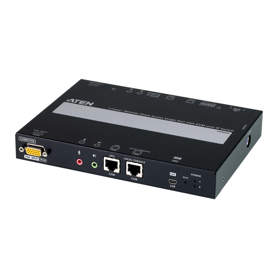
Page 22: Components
If the mode of USB IO Settings is set to Virtual Media, this port will not work. Reset button Press the Reset button for more than three (3) seconds to revert to factory settings. Power LED Lights Green when the CN9000 is powered up. -
Page 23: Cn9000 Rear View
AC power source, then plug the power adapter cable into any power jack. Plug another power adapter into an AC power source, then plug the power cable into the other CN9000 power jack. Note: Dual power operation is optional – the second power source is for back-up;... -
Page 24: Cn9000/Cn9900/Cn9950 Side View
CN9000/CN9600/CN9900/CN9950 User Manual CN9000/CN9900/CN9950 Side View Component Description Control Port This port is currently non-functional for CN9000/ CN9900/CN9950. -
Page 25: Cn9900/9950 Front View
If the mode of USB IO Settings is set to Virtual Media, this port will not work. Reset button Press the Reset button for more than three (3) seconds to revert to factory settings. Power LED Lights Green when the CN9000 is powered up. -
Page 26: Cn9900/9950 Rear View
AC power source, then plug the power adapter cable into any power jack. Plug another power adapter into an AC power source, then plug the power cable into the other CN9000 power jack. Note: Dual power operation is optional – the second power source is for back-up;... -
Page 27: Cn9600 Front View
Description PC/KVM Port Use the KVM cable provided with this package that links the CN9000/CN9600/CN9900/CN9950 to your PC / Server for this port. Connect the DVI video display, microphone and speakers to the server or the KVM switch you are installing. Each connector is color coded and marked with an appropriate icon. -
Page 28: Cn9600 Rear View
AC power source, then plug the power adapter cable into any power jack. Plug another power adapter into an AC power source, then plug the power cable into the other CN9000/ CN9600/CN9900/CN9950 power jack. Note: Dual power operation is optional – the second power source is for back-up;... -
Page 29: Hardware Setup
4. The power source for this product is intended to be supplied by a power adapter only, not a DC mains. Mounting The CN9000/CN9600/CN9900/CN9950 can be mounted on most standard 19” (1U) racks or mounted on a wall. The following illustrations are exemplified using CN9600. -
Page 30: Rack Mount
CN9000/CN9600/CN9900/CN9950 User Manual M3 x 5 Rack Mount 1. Position the device in the rack and align the holes in the mounting brackets with the holes on the rack. 2. Screw the mounting bracket to the rack. -
Page 31: Wall Mount
Chapter 2. Hardware Setup Wall Mount CN9000/CN9600/CN9900/CN9950 wall mounting is designed to be hung on a wall. 1. On the wall you wish to wall mount your unit, attach two screws as the hanger hooks for the bracket’s corresponding hanger keyholes (you may... -
Page 32: Hardware Installation
8. (Optional) Plug a second network cable into the other LAN port for dual LAN operation. 9. (Optional) For CN9000/CN9900/CN9950, connect the NC and C terminals to the server or PC for remote reboot operation (to be supported by upcoming firmware upgrade). -
Page 33: Cn9000
Chapter 2. Hardware Setup Note:The second power connection acts as power back-up. A second power adapter can be purchased from your ATEN supplier. CN9000... -
Page 34: Cn9600
CN9000/CN9600/CN9900/CN9950 User Manual CN9600... -
Page 35: Cn9900 / Cn9950
Chapter 2. Hardware Setup CN9900 / CN9950... - Page 36 CN9000/CN9600/CN9900/CN9950 User Manual DCE and DTE Ports You can connect different combinations of devices between DCE and DTE ports. If you intend to use a switch and PC combination, the switch can act as the DCE while the PC can act as the DTE. Therefore, connect the switch to the DTE port and the PC to the DCE port.
-
Page 37: Browser Login
To operate the CN9000/CN9600/CN9900/CN9950 from an Internet browser, do the following: 1. Open your browser and enter the IP address of the CN9000/CN9600/ CN9900/CN9950 you want to access in the browser's URL location bar. The default IP address for non-DHCP environment is 192.168.0.60. - Page 38 The CN9000/CN9600/CN9900/CN9950 login page appears: 3. Provide a valid Username and Password (set by the CN9000/CN9600/ CN9900/CN9950 administrator), and click Login to continue. Note: 1. If you are the administrator and are logging in for the first time, use the default username (administrator) and the default password (password).
-
Page 39: Main Screen
Chapter 3. Browser Login Main Screen After you have successfully logged in, the CN9000/CN9600/CN9900/CN9950 Main screen appears: The Main screen consists of the user menu in the left panel, with a Viewer icon (to launch the Java or WinClient Viewer) as well as a Logout icon displayed at the bottom of the menu. - Page 40 CN9000/CN9600/CN9900/CN9950 User Manual This Page Intentionally Left Blank...
-
Page 41: Configuration
Configuration Introduction The administration utilities, represented by the links and icons located on the left panel of the CN9000/CN9600/CN9900/CN9950 web page, are used to configure the device’s operating environment. This chapter discusses each of them in turn. Note: 1. As you make your configuration changes in each dialog box, click Save to apply the settings. -
Page 42: Basic Setting
User Management The User Management screen allows you to add, edit or remove user accounts to the CN9000/CN9600/CN9900/CN9950, as well as modify the role and permissions of each account: User Information Username: This is the user name of the account. -
Page 43: Permissions
Windows Client: Checking this allows a user to access the CN9000/ CN9600/CN9900/CN9950 via the Windows Client software. Config: Checking this allows the user to set up and modify the CN9000/ CN9600/CN9900/CN9950's operating environment. Telnet Client: Checking this allows a user to access the CN9000/CN9600/ CN9900/CN9950 via the network protocol of the same name. -
Page 44: Account Policy
CN9000/CN9600/CN9900/CN9950 User Manual Account Policy Set the parameters for the Username and Password. Minimum Username Length: Enter the minimum number (0 – 20) of characters required for a username (default is 6). Minimum Password Length: Enter the minimum number (0 – 20) of characters required for a password (default is 6). -
Page 45: Sessions
Chapter 4. Configuration Sessions The Sessions screen lets the administrator see all the users currently logged into the CN9000/CN9600/CN9900/CN9950, and provides information about each of their sessions. The meanings of the headings at the top of the page are fairly straightforward. -
Page 46: Maintenance
CN9000/CN9600/CN9900/CN9950 User Manual Maintenance The Maintenance screen allows the Administrator to upgrade the CN9000/ CN9600/CN9900/CN9950’s firmware, backup/restore the CN9000/CN9600/ CN9900/CN9950’s configuration settings and allows you to configure the unit’s setting using Terminal. Upgrade Main Firmware As new versions of the CN9000/CN9600/CN9900/CN9950 firmware become available, they can be downloaded from our website. -
Page 47: Update Display Information
Chapter 4. Configuration 5. After the upload completes, a message appears on the screen to show you the progress of the system upgrade. 6. When the system upgrade finishes, the current user will be logged out automatically and the system will inform the user that the system will reboot shortly. -
Page 48: Backup / Restore
CN9000/CN9600/CN9900/CN9950 User Manual Backup / Restore The Backup / Restore screen gives you the ability to back up the CN9000/ CN9600/CN9900/CN9950’s configuration and user profile information. Backed up User Account and Configuration information can be restored with the Restore section. Information currently configured on the CN9000/CN9600/ CN9900/CN9950 will be replaced with the information that you restore. - Page 49 Chapter 4. Configuration To restore a previous backup, do the following: 1. If a password was set when the backup was made, key the same password that you used to save the backup file in the Password field. If a password was not set, you can leave this field blank.
-
Page 50: Terminal
CN9000/CN9600/CN9900/CN9950 User Manual Terminal The Terminal section allows you to configure the unit using terminal commands. For a list of configurable commands, type help. -
Page 51: Advanced Setting
Device Name: To make it easier to manage installations that have more than one CN9000/CN9600/CN9900/CN9950, each one can be given a name. Enter a name (16 characters max.) for the CN9000/CN9600/ CN9900/CN9950 then click Save. MAC (1, 2) Address: The CN9000/CN9600/CN9900/CN9950’s MAC Address displays here. - Page 52 CN9000/CN9600/CN9900/CN9950 User Manual IPV6 Address / IPv6 Subnet Prefix Length: Displays the CN9000/ CN9600/CN9900/CN9950’s Internet Protocol Version 6 (128 bit) address (in the new format). See IPv6, page 138 for details.
-
Page 53: Network
Chapter 4. Configuration Network The Network screen is used to specify the CN9000/CN9600/CN9900/ CN9950’s network environment. -
Page 54: Ip Installer
Enabled, View Only, or Disabled for the IP Installer utility. See p. 135 for IP Installer details. Note: 1. If you select View Only, you will be able to see the CN9000/CN9600/ CN9900/CN9950 in the IP Installer’s Device List, but you will not be able to change the IP address. -
Page 55: Redundant Nic
IP address, 192.168.0.60. 2. If the CN9000/CN9600/CN9900/CN9950 is on a network that uses DHCP to assign network addresses, and you need to ascertain its IP address, you can use the IP installer. See IP Address Determination, page 135, for information. -
Page 56: Ipv6 Settings
3. Drop down the list to select the DDNS service you are registered with. 4. Key in the Username and Password that authenticates you with your DDNS service. 5. In the DDNS Retry Time field, key in how many hours the CN9000/ CN9600/CN9900/CN9950 waits before updating the DDNS server. -
Page 57: Anms
Chapter 4. Configuration ANMS The Advanced Network Management Settings screen allows you to set up login authentication and authorization management from external sources. It is divided into several sections, each of which is described in the sections that follow. Event Destination This section lets you configure the SMTP, Log Server, SNMP Trap and Syslog Server settings. -
Page 58: Smtp Settings
CN9000/CN9600/CN9900/CN9950 User Manual SMTP Settings To have the CN9000/CN9600/CN9900/CN9950 email reports from the SMTP server to you, do the following: 1. Check Enable report from the following SMTP server and key in the IP address and service port of your SMTP server. - Page 59 Note: The following SNMP trap events are sent: System Power On, Login Failure, and System Reset. Syslog Server To record all the events that take place on the CN9000/CN9600/CN9900/ CN9950 and write them to a Syslog server, do the following: 1. Check Enable.
-
Page 60: Authentication
4. Check Same as preferred setting if your Alternate RADIUS (type, timeout, retry and secret string) is the same as the preferred. 5. In the Timeout field, set the time in seconds that the CN9000/CN9600/ CN9900/CN9950 waits for a RADIUS server reply before it times out. - Page 61 To allow authentication and authorization via LDAP or LDAPS, the Active Directory’s LDAP Schema must be extended so that an extended attribute name for the CN9600 or CN9000/CN9900/CN9950 – iKVM50-userProfile or iKVM57-userProfile – is added as an optional attribute to the person class.
- Page 62 Use the following keyword for Radius and LDAP setting: su/[username] – the username must be a real user account that exists in the local account. For CN9600 and CN9000/CN9900/CN9950, respectively use iKVM50- userProfile and iKVM57-userProfile as LDAP attribute and su/ [username] as its attribute value.
-
Page 63: Security
The meanings of the entries are explained below. Login Fail Policy: Select the login failure policy that the CN9000/ CN9600/CN9900/CN9950 applies. Lock Client PC – If this is enabled, after the allowed number of failures have been exceeded, the computer attempting to log in is automatically locked out. -
Page 64: Filter
CN9000/CN9600/CN9900/CN9950 User Manual Filter IP and MAC Filters control access to the CN9000/CN9600/CN9900/CN9950 based on the IP and/or MAC addresses of the computers attempting to connect. A maximum of 100 IP filters and 100 MAC filters are allowed. If any filters have been configured, they appear in the IP Filter and/or MAC Filter list boxes. - Page 65 To delete a filter, select it in the filter list box and click Delete. The Filter section also lets administrators specify a Login String that users must include (in addition to the IP address) when they access the CN9000/CN9600/ CN9900/CN9950 with a browser. For example: 192.168.0.126/CN9000/CN9600/CN9900/CN9950...
-
Page 66: Encryption
CN9000/CN9600/CN9900/CN9950 User Manual Encryption These flexible encryption alternatives for keyboard/mouse, video, and virtual media data let you choose any combination of DES, 3DES, AES, RC4, or a Random cycle of any or all of them. Enabling encryption will affect system performance – no encryption offers the best performance while the more encryption, the greater the adverse effect. -
Page 67: Mode
Enable FIPS for FIPS security standard. The default is Disabled. Enable Multiuser Operation to permit more than one user to log into the CN9000/CN9600/CN9900/CN9950 at the same time. The default is Enabled. Enable Virtual Media Write allows redirected virtual media devices on a user’s system to send data to a remote server, as well as being able to have... - Page 68 CN9000/CN9600/CN9900/CN9950 User Manual There are two methods for establishing your private certificate: generating a self-signed certificate and importing a third-party certificate authority (CA) signed certificate. Generating a Self-Signed Certificate If you wish to create your own self-signed certificate, a free utility –...
-
Page 69: Certificate Signing Request
Chapter 4. Configuration Certificate Signing Request The Certificate Signing Request (CSR) section provides an automated way of obtaining and installing a CA signed SSL server certificate. To perform this operation, do the following: 1. Click Create CSR. The following dialog box appears: 2. - Page 70 Click Browse to locate the file; then click Upload to store it on the CN9000/CN9600/CN9900/CN9950. Note: When you upload the file, the CN9000/CN9600/CN9900/CN9950 checks the file to make sure the specified information still matches. If it does, the file is accepted; if not, it is rejected.
-
Page 71: Console Management
Chapter 4. Configuration Console Management This section discusses methods of opening the CN9000/CN9600/CN9900/ CN9950 console via OOBC (Out of Band Configuration) or serial connection. OOBC For this function to work, the serial device must be connected to the CPU COM (RS-232 DTE) port. - Page 72 Phone Number field. Enter the phone number of the modem that you want the CN9000/ CN9600/CN9900/CN9950 to dial back to in the Phone Number field. Enable Flexible Dial Back: When enabled, CN9000/CN9600/CN9900/ CN9950 dials back to any modem that is convenient for the user.
-
Page 73: Dial Out
ISP Settings: Specify the telephone number, account name (username), and password that you use to connect to your ISP. Dial Out Schedule: This entry sets up the times you want the CN9000/ CN9600/CN9900/CN9950 to dial out over the ISP connection. - Page 74 A setting of zero means it is always online. Dial Out Mail Configuration: This section provides email notification of problems that occur on the devices connected to the CN9000/CN9600/ CN9900/CN9950’s ports. Note: This email notification differs from the one configured under SMTP Settings in that it uses the ISP mail server rather than the internal company’s mail server.
-
Page 75: Serial Console
For this function to work, the serial device must be connected to the Local Console COM (RS-232 DCE) port. To configure the CN9000/CN9600/CN9900/CN9950 to interact with the connected serial device, you need to set its parameters to match the parameters of the device in the Port Property Settings. - Page 76 CN9000/CN9600/CN9900/CN9950 User Manual Stop Bits: This indicates that a character has been transmitted. Set this to match the stop bit setting of the serial console device. Choices are: 1 and 2. Default is 1 (which is the default for the majority of serial console devices).
- Page 77 Chapter 4. Configuration Note: When you enable serial port bypass, Port Alert Settings will be disabled. Port Alert Settings: You can specify up to 10 types of events (e.g., Power On). Enter them in the provided Alert String (1 - 10) fields.
-
Page 78: Date/Time
CN9000/CN9600/CN9900/CN9950 User Manual Date/Time The Date/Time dialog page sets the CN9000/CN9600/CN9900/CN9950 time parameters: Set the parameters according to the information below. Time Zone Use the drop-down menu to select the city that most closely corresponds to where it is at. -
Page 79: Network Time
Chapter 4. Configuration Click Set to save your settings. Network Time To have the time automatically synchronized to a network time server, do the following: 1. Check Enable auto adjustment. 2. Click the drop-down menu to select your preferred time server from the time server list –... -
Page 80: Mode
CN9000/CN9600/CN9900/CN9950 User Manual Mode Check Force All to Grayscale to enable this function. When enabled, the remote displays of all clients connected to the CN9000/CN9600/CN9900/ CN9950 are changed to grayscale. This can speed up I/O transfer in low bandwidth situations. -
Page 81: Exit Macro
Save. See System Macros on page 91 for details on creating exit macros. Reset Click Reset Default Values to reset the CN9000/CN9600/CN9900/CN9950 to the default system settings. If you wish to reboot the device after you log out, check Reset on exit. -
Page 82: Preferences
OSD Hotkey Select the keyboard combination to call the OSD function. Logout Timeout: When the session is idling, the time set here determines how long the CN9000/ CN9600/CN9900/CN9950 will wait for before terminating the session. Viewer Choose the detection order for the viewer you would like to use when viewing the remote server’s display. -
Page 83: Logs
Confirm Password: Repeat the new password. Click Change Password to apply your settings. Logs The CN9000/CN9600/CN9900/CN9950 logs all the events that take place on it. Following a reset, all logs are cleared. Click Log Information to view the logs: A maximum of 1024 events are kept in the log file. -
Page 84: Remote Console
CN9000/CN9600/CN9900/CN9950 User Manual Remote Console This section provides remote console related preference options. Remote Console Preview The preview in this screen shows a snapshot of the server’s display as follows: Clicking Refresh updates the snapshot of the remote display. Telnet Viewer If the Serial Console is enabled and a user has telnet access rights, then the “Open Telnet Client”... -
Page 85: Download
For details on the Log Server AP, refer to Chapter 9 on page 123. About Click About to see the current firmware version and copyright information of your CN9000/CN9600/CN9900/CN9950. Viewer Click the Viewer icon to call the remote client (Web Client, WinClient or Java Client) to view the remote server in a separate window. -
Page 86: Logout
CN9000/CN9600/CN9900/CN9950 User Manual Logout Click the Logout icon when you are done configuring the CN9000/CN9600/ CN9900/CN9950’s operating environment. This logs you out of the CN9000/ CN9600/CN9900/CN9950 GUI. -
Page 87: Accessing Remote Server
Chapter 5 Accessing Remote Server Introduction The remote server can be accessed as if it were your local system. A window will be presented and the remote server is displayed inside this window. You can maximize the window, drag the borders to resize the window and use the scrollbars to move around the screen. -
Page 88: Web, Windows And Java Client Viewer
CN9000/CN9600/CN9900/CN9950 User Manual Web, Windows and Java Client Viewer The Web, Windows and Java Client Viewer is accessible via a web browser. After you log into the web configuration page (see Logging In, page 25), click the Viewer icon on the left panel menu. A second or two after, the remote server’s desktop appears as a window on your desktop:... -
Page 89: The Windows Client Ap
Item Description Server List When you run the CN9000/CN9600/CN9900/CN9950 Windows Client program, it automatically searches the user's local LAN segment for CN9000/CN9600/CN9900/CN9950 units, and lists whichever ones it finds in this box. If you want... - Page 90 Connect Starts connecting to the CN9000/CN9600/CN9900/CN9950. Disconnect These buttons become active once you log into the CN9000/ CN9600/CN9900/CN9950. See page 79 for details. Switch to remote view Message panel The blank field on the right of the Server section shows the current status of the server connection.
- Page 91 In some cases, administrators do not wish to have users connect view to the CN9000/CN9600/CN9900/CN9950 with a browser. Switch to remote view solves this problem as it opens a window on the user’s desktop containing the remote server’s desktop that is the same as the one that appears with the browser-based Windows client.
-
Page 92: The Java Client Ap
CN9000/CN9600/CN9900/CN9950 User Manual The Java Client AP The Java Client AP is an AP program provided to make the CN9000/CN9600/ CN9900/CN9950 accessible to all platforms. It is, like the Windows Client AP, a Java Client program allowing you to access the Java Client without going through the browser configuration page. -
Page 93: The Windows Client Viewer
Chapter 6 The Windows Client Viewer The Win / Java Client Control Panel The control panels of the WinClient and Java Client are similar, with their differences explained below: In the Macros dialog box, Toggle Mouse Display is only available on WinClient. -
Page 94: Control Panel Functions
CN9000/CN9600/CN9900/CN9950 User Manual Control Panel Functions The Control Panel functions are described in the table below. Icon Function This is a toggle. Click to ping the Control Panel to the window where it is always displayed on top of other screen elements. Click again to have it display normally. - Page 95 Chapter 6. The Windows Client Viewer Icon Function Click to bring up the on-screen keyboard (see The On-Screen Keyboard, page 102). Click to select the mouse pointer type. Note: This icon changes depending on which mouse pointer type is selected (see Mouse Pointer Type, page 103). Click to toggle Automatic or Manual mouse sync.
- Page 96 CN9000/CN9600/CN9900/CN9950 User Manual Icon Function Click this to turn the microphone on or off. This icon grays out and becomes not functional when the microphone connected to the local console is enabled. To enable / disable the microphone from the local console OSD, see Local OSD, page 117.
-
Page 97: Macros
Chapter 6. The Windows Client Viewer Macros The Macros icon provides access to three functions found in the Macros dialog box: Hotkeys, User Macros, and System Macros. Each of these functions is described in the following sections. Hotkeys Various actions, corresponding to clicking the Control Panel icons, can be accomplished directly from the keyboard with hotkeys. - Page 98 CN9000/CN9600/CN9900/CN9950 User Manual To reset all the hotkeys to their default values, click Reset. An explanation of the Hotkey actions is given in the table below: Action Explanation Exit remote location Exits the remote view. This is equivalent to clicking the Exit icon on the Control Panel.
-
Page 99: User Macros
Chapter 6. The Windows Client Viewer User Macros User Macros are used to perform specific actions on the remote server. To create the macro, do the following: 1. Select the User Macros radio button, then click Add. 2. In the dialog box that comes up, replace the “New Macro” text with a name of your choice for the macro: 3. - Page 100 CN9000/CN9600/CN9900/CN9950 User Manual The dialog box disappears, and a small panel appears at the top left of the screen: 4. Press the keys for the macro. To pause macro recording, click Pause. To resume, click Pause again. Clicking Show brings up a dialog box that lists each keystroke that you make, together with the amount of time each one takes: ...
- Page 101 Chapter 6. The Windows Client Viewer 5. If you haven’t brought up the Show dialog, click Done when you have finished recording your macro. You return to the Macros dialog box shown in Step 1: 6. You can give each macro a set of hotkeys, as illustrated in Hotkeys, page 85.
- Page 102 CN9000/CN9600/CN9900/CN9950 User Manual After creating your macros, you can run them in any of three ways: 1. By using the hotkey (if one was assigned). 2. By opening the Macro List on the Control Panel and clicking the one you want (see , page 83).
-
Page 103: System Macros
Chapter 6. The Windows Client Viewer System Macros System Macros are used to create exit macros for when you close a session. For example, as an added measure of security, you could create a macro that sends the Winkey-L combination which would cause the remote device’s log in page to come up the next time the device was accessed. - Page 104 CN9000/CN9600/CN9900/CN9950 User Manual 4. Press the keys for the macro. To pause macro recording, click Pause. To resume, click Pause again. Clicking Show brings up a dialog box that lists each keystroke that you make, together with the amount of time each one takes (see page 92).
-
Page 105: Video Settings
(see Customization, page 67 for details). Note: 1. Information about the Search function is given on page 90. 2. Systems macros are stored on the CN9000/CN9600/CN9900/ CN9950, therefore macro names may not exceed 64 English alphanumeric character, and hotkey combinations may not exceed 256 Bytes (each key usually takes 3–5 Bytes). -
Page 106: Gamma Adjustment
CN9000/CN9600/CN9900/CN9950 User Manual Gamma Adjustment For greater control and if it is necessary to correct the gamma level for the remote video display, use the Gamma function of the Advanced Video Settings by clicking the Advanced button. For gamma level, there are ten preset and four user-defined levels to choose from. - Page 107 Depending on the network bandwidth, a high value may adversely affect response time. Enable Refresh The CN9000/CN9600/CN9900/CN9950 can redraw the screen every 1 to 99 seconds, eliminating unwanted artifacts from the screen. Select Enable Refresh and enter a number from 1 through 99.
-
Page 108: The Message Board
CN9000/CN9600/CN9900/CN9950 User Manual The Message Board To alleviate the possibility of access conflicts resulting from multiple user logins, the CN9000/CN9600/CN9900/CN9950 provides a message board that allows users to communicate with each other: The Button Bar The buttons on the Button Bar are toggles. Their actions are described in the... -
Page 109: Message Display Panel
Chapter 6. The Windows Client Viewer Message Display Panel Messages that users post to the board - as well as system messages - display in this panel. If you disable Chat, however, messages that get posted to the board will not appear. Compose Panel Key in the messages that you want to post to the board in this panel. -
Page 110: Virtual Media
CN9000/CN9600/CN9900/CN9950 User Manual Virtual Media The Virtual Media feature allows a drive, folder, image file, or removable disk on a local client computer to appear and act as if it were installed on the remote server. To enable this function, set the mode under USB IO Settings, page 68 to “Virtual Media”... - Page 111 Chapter 6. The Windows Client Viewer 2. Click Add and select the media source. Depending on your selection, additional dialog boxes appear enabling you to select the drive, file, folder, or removable disk you desire. See Virtual Media Support, page 156 for details about mounting these media types. 3.
- Page 112 CN9000/CN9600/CN9900/CN9950 User Manual Note: 1. If a redirected device cannot be written to, or if a user does not have write permissions, it appears in gray and cannot be selected. 2. See Virtual Media Support, page 156, for a list of supported virtual media types.
-
Page 113: Smart Card Reader
Chapter 6. The Windows Client Viewer Smart Card Reader Note: This feature is only available when using the WinClient Viewer or the Windows Client AP. The smart card reader function allows a reader plugged into a local client computer’s USB port to be redirected, and appear as if it were plugged into the remote server. -
Page 114: The On-Screen Keyboard
CN9000/CN9600/CN9900/CN9950 User Manual The On-Screen Keyboard The CN9000/CN9600/CN9900/CN9950 supports an on-screen keyboard, available in multiple languages, with all the standard keys for each supported language. Click this icon to pop up the on-screen keyboard: One of the major advantages of the on-screen keyboard is that if the keyboard languages of the remote and local systems are not the same, you do not have to change the configuration settings for either system. -
Page 115: Mouse Pointer Type
To display/hide the expanded keyboard keys, click the arrow to the right of the language list arrow. Mouse Pointer Type The CN9000/CN9600/CN9900/CN9950 offers a number of mouse pointer options when working in the remote display. Click this icon to select the type that you would like to work with: Note: 1. -
Page 116: Mouse Dynasync Mode
CN9000/CN9600/CN9900/CN9950 User Manual Mouse DynaSync Mode Clicking this icon selects whether synchronization of the local and remote mouse pointers is accomplished either automatically or manually. The icon on the toolbar indicates the synchronization mode status as follows: Icon Function The green mark on this icon indicates that Mouse DynaSync is available and is enabled. -
Page 117: Mac And Linux Considerations
Chapter 6. The Windows Client Viewer Mac and Linux Considerations For Mac OS versions 10.4.11 or later, there is a second DynaSync setting to choose from. If the default Mouse DynaSync result is not satisfactory, try the Mac 2 setting. To select Mac 2, right click in the text area of the →... -
Page 118: Open Gui (Configuration)
CN9000/CN9600/CN9900/CN9950 User Manual Open GUI (Configuration) Clicking the Open GUI icon for viewer-based configuration. The sidebar menu items available on this page are based on the user’s permissions. For information on how to use these functions, refer to Configuration on page 29. -
Page 119: Control Panel Configuration
Chapter 6. The Windows Client Viewer Control Panel Configuration Clicking the Customize Control Panel icon brings up a dialog box that allows you to configure the items that appear on the Control Panel, as well as its graphical settings: The dialog box is organized into five main sections as described in the table below: Item Description... - Page 120 Control Panel (See the Control Panel diagram on page 81 for an example.) Snapshot These settings let the user configure the CN9000/CN9600/CN9900/ CN9950’s screen capture parameters (see the Snapshot description under The Win / Java Client Control Panel, page 81): ...
-
Page 121: The Web Client Control Panel
Screen Mode and Fit to Window. Click to toggle the remote display between color and grayscale views. Panel Array Mode is not applicable to CN9000/CN9600/CN9900/ CN9950. Click for a drop-down menu of the available online port(s) and click to select the port you wish to connect to. -
Page 122: Web Client Video Settings
CN9000/CN9600/CN9900/CN9950 User Manual Click to select the mouse pointer type. Note: This icon changes depending on which mouse pointer type is selected (Refer to Web Client Mouse Pointer Type, page 111 for more information). Click for a menu of mouse sync modes (Refer to Web Client Mouse Sync Mode, page 113 for a complete explanation of this feature). -
Page 123: Web Client On-Screen Keyboard
Chapter 6. The Windows Client Viewer Options Usage Enhanced Text Check this to solve video display problems related to video screen Mode resolution that affect some interface systems (e.g., Sun Blade 1000 and other servers). This setting can improve the image color on some displays. -
Page 124: Virtual Media
CN9000/CN9600/CN9900/CN9950 User Manual Note: 1. Available options will depend on the browser. For example, Internet Explorer has Dual and Crosshairs types while Chrome has Dual, Crosshairs and Single Cursor. 2. The icon on the Control Panel changes to match your pointer choice. -
Page 125: Web Client Mouse Sync Mode
Chapter 6. The Windows Client Viewer Adding Virtual Media via Internet Explorer To setup a Virtual Media device using Internet Explorer, do the following: 1. Click the Virtual Media icon to bring up the Virtual Media Control. 2. Select an ISO file by clicking and click Open. - Page 126 CN9000/CN9600/CN9900/CN9950 User Manual This Page Intentionally Left Blank...
-
Page 127: Local Access
Rear View Local console ports connection for local access This access is similar to using the server/computer directly. The CN9000/ CN9600/CN9900/CN9950 is able to split the signal to both the local and remote consoles. The local console has priority by default. - Page 128 CN9000/CN9600/CN9900/CN9950 User Manual A login page will first appear: Enter the username and password to enter the configuration page. Note: If you are the administrator and are logging in for the first time, use the default username (administrator) and the default password (password).
-
Page 129: Local Osd
Chapter 7. Local Access Local OSD The configuration page is the same as the web browser version, refer to Configuration on page 29 for more information. To enable / disable the speakers and microphone connected on the local console, press icons located on the lower-right corner of the OSD. -
Page 130: Laptop Usb Console (Luc)
With the laptop, you can then access and edit the CN9000/CN9600/CN9900/ CN9950 application. To enable this function, you have to set the USB IO settings of CN9000/ CN9600/CN9900/CN9950 to LUC mode first. Click the drop-down menu in the CN9000/CN9600/CN9900/CN9950 browser configuration (Configuration location: Advanced Settings -->... - Page 131 Chapter 7. Local Access 4. Enter the Username/Password (administrator/password) and click OK. 5. If the login was successful, the Remote View button becomes active. 6. Click Remote View to bring up the Laptop Console Main Page. If this is the first time you log into the system, the system will prompt you to change the password.
- Page 132 CN9000/CN9600/CN9900/CN9950 User Manual This Page Intentionally Left Blank...
-
Page 133: The Log File
The Log File The Log File Screen The CN9000/CN9600/CN9900/CN9950 logs all the events that take place on it. Following a reset, all logs are cleared. To view the contents of the log file, click the Log icon at the center left of the page. A screen similar to the one below appears: A maximum of 1024 events are kept in the log file. - Page 134 CN9000/CN9600/CN9900/CN9950 User Manual This Page Intentionally Left Blank...
-
Page 135: The Log Server
Chapter 9 The Log Server The Log Server is a Windows-based administrative utility that records all the events that take place on selected CN9000/CN9600/CN9900/CN9950 units and writes them to a searchable database. Installation 1. In the web GUI, go to the Download page. Refer to Download, page 73 for more details. -
Page 136: The Menu Bar
The Menu bar consists of four items: Configure Events Options Help These are discussed in the sections that follow. Note: If the Menu Bar appears to be disabled, click in the CN9000/CN9600/ CN9900/CN9950 List window to enable it. -
Page 137: Configure
Configure The Configure menu contains three items: Add, Edit, and Delete. They are used to add new device units to the CN9000/CN9600/CN9900/CN9950 List, edit the information for units already on the list, or delete device units from the list. To add a CN9000/CN9600/CN9900/CN9950 to the List, click Add. -
Page 138: Events
New search This is one of three radio buttons that define the scope of the search. If it is selected, the search is performed on all the events in the database for the selected CN9000/CN9600/ CN9900/CN9950. Search last results This is a secondary search performed on the events that resulted from the last search. -
Page 139: Maintenance
Chapter 9. The Log Server Priority List Sets the level for how detailed the search results display should be. Least is the most general; Most is the most specific. Least results appear in black; Less results appear in blue; Most results appear in red. Start Date Select the date that you want the search to start from. -
Page 140: Help
Log Server to track (see Configure, page 125). The lower (Event) panel displays the log events for the currently selected CN9000/CN9600/CN9900/CN9950 (the highlighted one - if there are more than one). To select a CN9000/CN9600/CN9900/CN9950 unit in the list, simply click on it. -
Page 141: The List Panel
This is the IP Address or DNS name that was given to the CN9000/CN9600/CN9900/CN9950 when it was added to the Log Server (see Configure, page 125). Port This is the port number that was assigned to the CN9000/ CN9600/CN9900/CN9950 when it was added to the Log Server (see Configure, page 125). Connection If the Log Server is connected to the CN9000/CN9600/ CN9900/CN9950, this field displays Connected. - Page 142 CN9000/CN9600/CN9900/CN9950 User Manual This Page Intentionally Left Blank...
-
Page 143: Appendix
Appendix Safety Instructions General This product is for indoor use only. Read all of these instructions. Save them for future reference. Follow all warnings and instructions marked on the device. Do not place the device on any unstable surface (cart, stand, table, etc.). If the device falls, serious damage will result. - Page 144 CN9000/CN9600/CN9900/CN9950 User Manual Unplug the power cable before removing the power supply. If the system has multiple sources of power, disconnect power from the system by unplugging all power cables from the power supplies. Never push objects of any kind into or through cabinet slots. They may touch dangerous voltage points or short out parts resulting in a risk of fire or electrical shock.
-
Page 145: Rack Mounting
Appendix Rack Mounting Before working on the rack, make sure that the stabilizers are secured to the rack, extended to the floor, and that the full weight of the rack rests on the floor. Install front and side stabilizers on a single rack or front stabilizers for joined multiple racks before working on the rack. -
Page 146: Technical Support
CN9000/CN9600/CN9900/CN9950 User Manual Technical Support International For online technical support – including troubleshooting, documentation, and software updates: http://eservice.aten.com For telephone support, see Telephone Support, page iii. North America Email Support support@aten-usa.com Online Troubleshooting http://eservice.aten.com Technical Documentation Support Software Updates... -
Page 147: Ip Address Determination
If you are an administrator logging in for the first time, you need to access the CN9000/CN9600/CN9900/CN9950 in order to give it an IP address that users can connect to. There are several methods to choose from. In each case, your computer must be on the same network segment as the CN9000/CN9600/ CN9900/CN9950. -
Page 148: Browser
2. Specify the switch's default IP address (192.168.0.60) in your browser, and you will be able to connect. 3. Assign a fixed IP address for the CN9000/CN9600/CN9900/CN9950 that is suitable for the network segment that it resides on. 4. After you log out, reset your computer's IP address to its original value. - Page 149 Appendix You can now use this network address, or you can change it in the Network menu. See page 43 for details.
-
Page 150: Ipv6
IP field of the Server panel (See p. 77). Note: 1. To log in with the Link Local IPv6 Address, the client computer must be on the same local network segment as the CN9000/CN9600/ CN9900/CN9950 2. The %5 is the %interface used by the client computer. To see your client computer’s IPv6 address: from the command line issue the... -
Page 151: Ipv6 Stateless Autoconfiguration
Appendix IPv6 Stateless Autoconfiguration If the CN9000/CN9600/CN9900/CN9950’s network environment contains a device (such as a router) that supports the IPv6 Stateless Autoconfiguration function, the CN9000/CN9600/CN9900/CN9950 can obtain its prefix information from that device in order to generate its IPv6 address. For example, 2001::74ff:fe6e:59. -
Page 152: Port Forwarding
For example, if the CN9000/CN9600/CN9900/CN9950 connected to a particular router has an IP address of 192.168.1.180, you would log into your router’s setup program and access the Port Forwarding (sometimes referred to... -
Page 153: Keyboard Emulation
Appendix Keyboard Emulation PC compatible (101/104 key) keyboards can emulate the functions of the Sun and Mac keyboards. The emulation mappings are listed in the table below. PC Keyboard Sun Keyboard PC Keyboard Mac Keyboard [Ctrl] [T] Stop [Shift] Shift [Ctrl] [F2] Again [Ctrl]... -
Page 154: Serial Port Pin Assignment
CN9000/CN9600/CN9900/CN9950 User Manual Serial Port Pin Assignment Pin assignment for the CPU COM (RS-232 DTE) port is given in the table below: Assignment RJ-45 Female Pin assignment for the Local Console COM (RS-232 DCE) port is given in the table below:... -
Page 155: Trusted Certificates
Appendix Note: If you are connecting to the DCE port using a Cisco Console Cable, a null modem cable or null modem converter is required. Trusted Certificates Overview When you try to log in to the device from your browser, a Security Alert message appears to inform you that the device’s certificate is not trusted, and asks if you want to proceed. -
Page 156: Installing The Certificate
CN9000/CN9600/CN9900/CN9950 User Manual Installing the Certificate To install the certificate, do the following: 3. In the Security Alert dialog box, click View Certificate. The Certificate Information dialog box appears: Note: There is a red and white X logo over the certificate to indicate that it is not trusted. -
Page 157: Certificate Trusted
When you click View Certificate, you can see that the red and white X logo is no longer present – further indication that the certificate is trusted: Mismatch Considerations If the site name or IP address used for generating the certificate no longer matches the current address of the CN9000/CN9600/CN9900/CN9950 a mismatch warning occurs:... - Page 158 CN9000/CN9600/CN9900/CN9950 User Manual You can click Yes to go on, or you can disable mismatch checking. To disable mismatch checking, do the following: 1. After the page you are logging in to comes up open the browser’s Tools → menu; Select Internet Options Advanced.
-
Page 159: Self-Signed Private Certificates
[Enter] until all the parameters have been keyed in). 2. If there are spaces in the input, surround the entry in quotes (e.g., “ATEN International”). To avoid having to input information during key generation the following additional parameters can be used: /C /ST /L /O /OU /CN /emailAddress. -
Page 160: Troubleshooting
1. If the CN9000/CN9600/CN9900/CN9950 is connected to a KVM switch, make sure to power it on before pow- ering on the switch. 2. If the KVM switch was started before the CN9000/ CN9600/CN9900/CN9950, reset or restart the KVM switch. The CN9000/CN9600/CN9900/CN9950 needs to be reset (see Upgrade Main Firmware, page 34, point 1). - Page 161 Installer. work properly. Make sure to turn off your firewall and/or antivirus software temporarily in order for the audio-discover to work properly. Make sure the ATEN over IP unit and the PC are under the same network segment.
-
Page 162: Windows
CN9000/CN9600/CN9900/CN9950 User Manual Windows Problem Resolution When I log in, the browser 1. The certificate’s name is not found on Microsoft’s list of generates a CA Root Trusted Authorities. The certificate can be trusted. certificate is not trusted, See Trusted Certificates, page 143, for details. -
Page 163: Java
CN9000/CN9600/CN9900/ your computer. CN9950 2. Make sure to include the correct login string when you specify the CN9000/CN9600/ CN9900/CN9950's IP address. 3. Close the Java Applet, reopen it, and try again. I have installed the latest Java There may be issues with the latest version JRE, but I am having performance because it is so new. -
Page 164: Sun Systems
CN9000/CN9600/CN9900/CN9950 User Manual Sun Systems Problem Resolution Video display problems with The display resolution should be set to 1024 x 768: HDB15 interface systems (e.g., Under Text Mode: Sun Blade 1000 servers). 1. Go to OK mode and issue the following com-... -
Page 165: Mac Systems
Appendix Mac Systems Problem Resolution The local and remote There are two USB I/O settings for the Mac: Mac 1, and mouse pointers do not Mac 2 (see Customization, page 67). In general, Mac 1 sync. works with older operating system versions, whereas Mac 2 works with the newer ones. -
Page 166: Additional Mouse Synchronization Procedures
CN9000/CN9600/CN9900/CN9950 User Manual Additional Mouse Synchronization Procedures If the mouse synchronization procedures mentioned in the manual fail to resolve mouse pointer problems for particular computers, try the following: Windows: Note: In order for the local and remote mouses to synchronize, you must use the generic mouse driver supplied with the MS operating system. -
Page 167: Sun / Linux
Appendix b) Click the Pointer Options tab c) Bring the mouse speed to the middle position (6 units in from the left) d) Disable Enhance Pointer Precision 3. Windows ME: Set the mouse speed to the middle position; disable mouse acceleration (click Advanced to get the dialog box for this). -
Page 168: Virtual Media Support
CN9000/CN9600/CN9900/CN9950 User Manual Virtual Media Support WinClient ActiveX Viewer / WinClient AP IDE CDROM/DVD-ROM Drives – Read Only IDE Hard Drives – Read Only USB CD ROM/DVD-ROM Drives – Read Only USB Hard Drives – Read/Write* ... -
Page 169: Administrator Login Failure
4. When the front panel LEDs flash, power off the switch. 5. Remove the jumper cap from J13. 6. Close the housing and power on the CN9000/CN9600/CN9900/CN9950. After you clear and reset the system database, you can use the default... -
Page 170: Specifications
CN9000/CN9600/CN9900/CN9950 User Manual Specifications CN9000 Connectors Console Ports 2 x USB Type-A Female (White) 1 x VGA Female (Blue) 1 x 3.5mm Audio Jack Female (Green) 1 x 3.5mm Audio Jack Female (Pink) KVM Ports 1 x SPHD / VGA Female (Yellow) 1 x 3.5mm Audio Jack Female (Green) -
Page 171: Cn9600
Appendix Physical Properties Housing Metal Weight 0.86 kg (1.90 lb) Dimensions (L x W x H) 20.00 x 15.41 x 2.85 cm (7.87 x 6.07 x 1.12 in.) CN9600 Connectors Console Ports 2 x USB Type-A Female (White) 1 x DVI-D Female (White) 1 x 3.5mm Audio Jack Female (Green) 1 x 3.5mm Audio Jack Female (Pink) KVM Ports... -
Page 172: Cn9900 / Cn9950
CN9000/CN9600/CN9900/CN9950 User Manual Environment Operating Temperature 0–50ºC (CN9600) 0–40ºC (Power Adapter) Storage Temperature –20–60ºC Humidity 0–80% RH, Non-condensing Physical Properties Housing Metal Weight 0.84 kg (1.85 lb) Dimensions (L x W x H) 20.00 x 15.49 x 2.85 cm (7.87 x 6.1 x 1.12 in.) - Page 173 Appendix LEDs Power 2 (Green) Video Local Console & Remote 1920 x 1200 @ 60Hz (CN9900) 4096 x 2160 @ 30Hz (CN9950) Power Consumption DC 5 V: 6.5 W: 35 BTU (CN9900) DC 5 V: 9.79 W: 50 BTU (CN9950) Environment Operating Temperature 0–50ºC (CN9900/CN9950)
-
Page 174: Limited Warranty
What is covered by the Limited Hardware Warranty ATEN will provide a repair service, without charge, during the Warranty Period. If a product is detective, ATEN will, at its discretion, have the option to (1) repair said product with new or repaired components, or (2) replace the entire product with an identical product or with a similar product which fulfills the same function as the defective product.