
Related Manuals for Mitsubishi SRK20ZSXA-W


Summary of Contents for Mitsubishi SRK20ZSXA-W
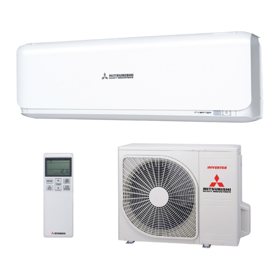
- Page 1 USER’S MANUAL AIR-CONDITIONER SRK20ZSXA-W SRK25ZSXA-W SRK35ZSXA-W SRK50ZSXA-W SRK60ZSXA-W RLF012A204A RLF012A204_EN_1-36.indd 1 7/29/2017 6:11:36 PM...
-
Page 2: Table Of Contents
Thank you for purchasing a MITSUBISHI HEAVY INDUSTRIES THERMAL SYSTEMS, LTD. Air-Conditioner. To get the best long-lasting performance, please read and follow this user’s manual carefully before using your air-conditioner. After reading, please store the manual in a safe place and refer to it for operational questions or in the event of any irregularities. -
Page 3: Safety Precautions
Safety precautions • Before starting to use the system, please read these “Safety precautions” carefully to ensure proper operation of the system. • When you have read this user’s manual, please keep it safely. If someone else takes over as user, make sure that the manual is also passed on to the new user. - Page 4 ❚ INSTALLATION PRECAUTIONS WARNING • The system is for domestic and residential use. If used in severe environments, such as an engineering workplace, the equipment may function poorly. • The system must be installed by your dealer or a qualified installer. It is not advisable to install the system by yourself, as faulty handling may cause leakage of water, electric shock or fire.
- Page 5 ❚ Safety precautions ❚ OPERATION PRECAUTIONS WARNING • Children shall not play with the • Cleaning and user maintenance shall air-conditioner. not be made by children without • Do not expose yourself to the cooling supervision. • Do not insert anything into the air air for a long period.
- Page 6 ❚ Safety precautions CAUTION • Do not touch the aluminum fins on the • Do not shut off the power source heat exchanger. immediately after stopping the operation. It may result in injury. • Do not place household electrical Wait at least 5 minutes, otherwise there is appliances or household items under- a risk of water leakage or breakdown.
-
Page 7: Tips For Effective Operation
❚ Safety precautions ❚ PRECAUTIONS FOR RELOCATION OR REPAIRS WARNING • Do not perform any repairs or modifications by yourself. Consult the dealer if the unit requires repair. If you repair or modify the unit, it can cause water leaks, electric shocks or fire. •... -
Page 8: Name Of Each Part And Its Function
Name of each part and its function INDOOR UNIT Air-cleaning filter Room temperature Air inlet panel Air inlet Page 32 sensor Page 30, 31 • Allergen clear filter (Light orange) Air filters Page 30 • Photocatalytic washable deodorizing filter (Orange) •... - Page 9 Name of each part and its function Unit display section TIMER light (yellow) Unit ON/OFF button Illuminates during TIMER operation. This button can be used for turning on/off Page 18-24 the unit when a remote control is not available. Page 9 RUN light (green/blue) Remote control signal receiver •...
-
Page 10: Remote Control
Remote control Setting the batteries NOTE Pull out the cover. • Do not use old and new batteries together. • Remove the batteries when the remote control is not used for a long period. • The recommended effective period of a battery conforming to JIS or IEC Insert new batteries. -
Page 11: Installing Two Air-Conditioners In The Same Room
Installing two air-conditioners in the same room ■ When two air-conditioners are installed in the same room, use this setting when the two air-conditioners are not operated with one remote control. Set the remote control and indoor unit. Setting the remote control Setting an indoor unit Pull out the cover and take out Turn off the power source and turn it on after 1 minute. -
Page 12: Airflow Range Setting
Airflow range setting ■ Take the air-conditioner location into account and adjust the left/right airflow range to maximize air-conditioning. If the air-conditioner is running, press the ON/OFF button to stop. The airflow range setting cannot be made while the unit is running. Press the AIR FLOW U/D (UP/DOWN) button and the AIR FLOW L/R (LEFT/RIGHT) button together for 5 seconds or more. - Page 13 Motion sensor setting ■ According to the installation location of the indoor unit, turn the sensor to the right or left until it clicks into position. (The orientation of the application range can be changed laterally by approximately 20 degrees.) Left End Installation Center Installation Right End Installation...
-
Page 14: Operation And Display Section For Remote Control
Operation and display section for remote control Transmission section ON/OFF (luminous) button OPERATION MODE select button Each time the button is pressed, the Press to start operation, press again mode changes. to stop. Page 14,16 TEMPERATURE button FAN SPEED button This button sets the room temperature. -
Page 15: Current Time Setting
Current time setting ■ When inserting the batteries, the current time is automatically set to time setting mode. Mon and 13:00 are displayed as the current time. Set a correct day of the week and time. Example: Set to Sat 10:30. Press the TIME SET UP switch. -
Page 16: Temperature Adjustment During Auto Mode
Temperature adjustment during AUTO mode ■ Default preset temperature during AUTO mode is 24°C for both cooling and heating mode. However, it can be adjusted (Minimum 18°C, Maximum 30°C) using button or button. Press the“ or (TEMP)” button. When it is a little cold Press the button. -
Page 17: Cool/Heat/Dry/Fan Mode Operation
COOL/HEAT/DRY/FAN mode operation Press the MODE button. Set to a required mode. (COOL), (HEAT), (DRY), (FAN) Press the ON/OFF button. Press the TEMP button. Press button for the preferred temperature. Recommendation COOL HEAT 26 °C - 28 °C 22 °C - 24 °C 24 °C - 26 °C —... -
Page 18: Airflow Direction Adjustment
Airflow direction adjustment ■ Up/down direction can be adjusted with the AIR FLOW U/D (UP/DOWN) button on the remote control. Every time you press this button, the mode changes as follows: Change on AIR FLOW (UP/DOWN) mode. (Flap stopped) (Swing) ■... -
Page 19: Sleep Timer Operation
SLEEP TIMER operation ■ The unit will stop automatically after the set time lapses. The set temperature is automatically adjusted according to the lapse time in order to avoid too much cooling or heating. Page 20 Press the SLEEP button. ■... -
Page 20: On Timer Operation
ON TIMER operation ■ Operation starts 5 to 60 minutes before the set time so that the room temperature reaches the optimum temperature at the set time. Page 20 ON TIMER operation can be set regardless of whether the air-conditioner is running or not. Example: When the preferred room temperature is required at 8:00. -
Page 21: On Timer + Off Timer Operation
ON TIMER + OFF TIMER operation ■ This is the combined timer operation of ON TIMER and OFF TIMER. Example: Present time is 21:00. The air-conditioner running. When it is preferred to stop at 22:30, and then start operation at 8:00, near the set temperature. -
Page 22: Weekly Timer Operation
WEEKLY TIMER operation ■ Up to 4 programs with timer operation (ON TIMER / OFF TIMER) are available for each day of the week. Maximum 28 programs per week are available. Once this has been set, the timer operation will be repeated at the same programs every week unless the WEEKLY TIMER is canceled. - Page 23 Setting mode <Individual setting> Set after setting the current day of the week and the time. Press the PROGRAM button. and current day of the week blink. Press the “ or (TIMER)” button. Select a day of the week to be reserved. Every time the button is pressed, the display is switched in the order of:...
- Page 24 Press the “ or (TIMER)” button. Set a time. Every time the button is pressed, the display is switched in the order of: 0:00 0:10 0:20 1:00 1:10 (Units of ten minutes) Every time the button is pressed, the display is switched in the order of: 0:00 23:50 23:40 23:00 22:50...
- Page 25 How to cancel the setting <Individual setting> Press the PROGRAM button. and current day of the week blink. Press the “ or (TIMER)” button. Select a day of the week to be canceled. Press the SET button. The day of the week is determined and the program number blinks. Press the “...
-
Page 26: High Power/Eco Operation
HIGH POWER/ECO operation Press the ON/OFF button. Press the HI/ECO button. • When the operating mode is AUTO, COOL or HEAT Every time the HI/ECO button is pressed, the display is switched in the order of: No display (HIGH POWER) (ECO) (Normal operation) •... -
Page 27: Night Setback Operation
NIGHT SETBACK operation ■ During the cold season, the room temperature can be maintained at a comfortable level during the absence, at night, and while the room is unattended. The air-conditioner maintains the constant temperature at about 10°C. Press the NIGHT SETBACK button. Every time the NIGHT SETBACK button is pressed, the display is switched in the order of: No display... -
Page 28: Menu Function
MENU function ■ MENU function is used for setting the display brightness adjustment, AUTO OFF operation, SELF CLEAN operation and PRESET opera- tion. Every time the MENU switch is pressed with the tip of a ballpoint pen, etc., the display is switched in order of: Display brightness AUTO OFF adjustment... -
Page 29: Auto Off Operation
AUTO OFF operation ■ In order to prevent the air-conditioner from continuing to operate although the person(s) has already left the room, the air-conditioner automatically stops approximately 1 hour (or 2 hours) after the sensor judges that there is no one in the room. Select the AUTO OFF operation by pressing the MENU switch. -
Page 30: Self Clean Operation
SELF CLEAN operation ■ SELF CLEAN operation should be run after AUTO, COOL and DRY operation to remove the moisture from inside of the indoor unit and control the growth of mold and bacteria. Select the SELF CLEAN operation by pressing the MENU switch. -
Page 31: Maintenance
Maintenance Before maintenance During the operational season Cleaning the air filter Standard interval is once Turn off the power source. every two week Remove the air filter • Pull up the air inlet panel forward. • Lightly hold the knobs both sides and lift a little •... - Page 32 How to remove and install the air inlet panel 1. Basic structure A: Outer panel of air inlet panel : Hook B: Inner panel of air inlet panel Main body NOTE • Air inlet panel’s open/close of this unit is driven by electrical motor. •...
- Page 33 Cooling/heating is affected by an air filter clogged up with dust etc., and the operation noise becomes louder. It NOTE may also use extra electricity. Please clean the air filter at appropriate intervals. At the end of the season At the beginning of the season Perform the fan operation for 2 to 3 hours.
-
Page 34: Proper Installation
Proper installation Suitable installation position • Do not put any obstruction in front of the indoor unit, preventing proper ventilation and functioning. • Do not install the unit in any of the following places: − Where there is a danger of leaking flammable gases. −... -
Page 35: Notice
Notice Airflow Air is not blown out when starting the HEATING operation. Airflow has stopped to prevent blowing out of cold air until the indoor heat exchanger has warmed up. (2 to 5 minutes) RUN light blinks slowly (1.5 seconds ON, 0.5 seconds OFF) Air is not blown out for 5 to 15 minutes or cool air is When outdoor temperature is low and humidity is high, the blown out for a moment at HEATING operation. -
Page 36: Contact Your Dealer
Contact your dealer ■ Turn off the power switch immediately and inform your dealer in any of the following situations: • The fuse or switch blows continuously. • The cable becomes extremely hot. The covering of the cable is cracked. •... -
Page 37: Self Diagnosis Function
Self diagnosis function ■ We are constantly trying to do better service to our customers by installing such judges that show abnormality of each function as follows RUN light Description of trouble Cause Indoor heat exchanger sensor 1 • Broken heat exchanger sensor 1 wire, poor connector 1-time flash error connection... - Page 38 MITSUBISHI HEAVY INDUSTRIES THERMAL SYSTEMS, LTD. 16-5 Konan 2-chome, Minato-ku, Tokyo, 108-8215, Japan http://www.mhi-mth.co.jp/en/ MITSUBISHI HEAVY INDUSTRIES AIR-CONDITIONERS AUSTRALIA, PTY. LTD. 9C Commercial Road Kingsgrove NSW 2208 PO BOX 318 Kingsgrove NSW 1480 Tel : +61-2-8571-7977 Fax: +61-2-8571-7992 https://www.mhiaa.com.au/ RLF012A204_EN_1-36.indd 1...