
Related Manuals for Garmin GTS 8 Series


Summary of Contents for Garmin GTS 8 Series
- Page 1 GTS 8XX/GPA 65 Installation Manual (Includes the GA 58 Antenna) 190-00587-00 April, 2009 Revision 4TP...
- Page 2 Garmin. Garmin hereby grants permission to download a single copy of this manual and of any revision to this manual onto a hard drive or other electronic storage medium to be viewed and...
- Page 3 California to cause cancer, birth defects, or reproductive harm. This Notice is being provided in accordance with California's Proposition 65. If you have any questions or would like additional information, please refer site www.garmin.com/prop65. GTS 8XX/GPA 65 Installation Manual Page i 190-00587-00 Revision 4TP...
- Page 4 This page intentionally left blank Page ii GTS 8XX/GPA 65 Installation Manual Revision 4TP 190-00587-00...
-
Page 5: Table Of Contents
TABLE OF CONTENTS PARAGRAPH PAGE GENERAL DESCRIPTION......................1-1 1.1 Introduction............................1-1 1.2 Equipment Description ........................1-1 1.3 Interface Summary..........................1-1 1.4 Technical Specifications ........................1-2 1.5 Certification ............................1-4 1.6 Reference Documents ........................1-8 1.7 Limited Warranty..........................1-9 INSTALLATION OVERVIEW ......................2-1 2.1 Introduction............................2-1 2.2 Installation Considerations ........................2-3 2.3 Electrical Bonding ..........................2-5 2.4 Cabling and Wiring..........................2-5 2.5 Cooling Requirements ........................2-15 2.6 Mounting Requirements ........................2-16... - Page 6 2-7 RG-400/RG-142 Coaxial Cable Stripping Dimensions ..............2-14 2-8 Ferrule and Crimp Die Positioning ....................2-14 2-9 Heat Shrink Positioning ........................2-15 2-10 GTS 8XX Vertical Installation Rack (Garmin P/N 115-00781-00) ..........2-16 2-11 GTS 8XX Horizontal Installation Rack (Garmin P/N 115-00784-00) ..........2-16 3-1 Engaging QMA Connectors.......................3-3 3-2 Disengaging QMA Connectors......................3-4...
- Page 7 LIST OF TABLES TABLE PAGE 2-1 GPA 65 Minimum Wiring Requirements ..................2-6 2-2 Cable Types and QMA Connectors ....................2-11 2-3 Recommended Coaxial Length......................2-12 2-4 Coaxial Cable Set Length Tolerance ....................2-13 3-1 Socket and Pin Contact part Numbers ....................3-1 3-2 Socket Contact MIL SPEC M39029/5-115 Crimp Tooling...............3-1 3-3 Pin Contact GPN 336-00021-00 MIL SPEC M39029/58-360 Crimp Tooling .........3-2 3-4 Pin Socket Contacts GPN 336-00022-00 MIL SPEC M39029/63-368 and GPN 336-00023-00 Crimp Tooling...............................3-2...
- Page 8 The table is current at the time of publication of this manual (see date on front cover) and is subject to change without notice. Authorized Garmin Sales and Service Centers are encouraged to access the most up-to-date bulletin and advisory information on the Garmin Dealer Resource web site at www.garmin.com...
-
Page 9: General Description
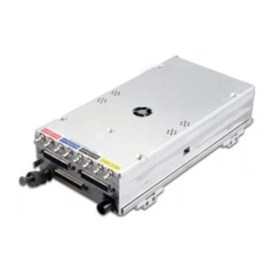
GENERAL DESCRIPTION 1.1 Introduction This manual presents mechanical and electrical installation requirements for installing the GTS 8XX/GPA 65 Traffic Advisory System (TAS) and Traffic Collision Avoidance System (TCAS I). 1.2 Equipment Description The GTS 8XX is a microprocessor-based Line Replaceable Unit (LRU) that uses active interrogations of Mode S (GTS 820 and GTS 850 only) and Mode C transponders to provide Traffic Advisories to the pilot. -
Page 10: Technical Specifications
GPA 65 PA/LNA Environmental Qualification Form, Garmin part number 005-00323-22 GA 58 Antenna Environmental Qualification Form, Garmin part number 005-00232-23 To obtain a copy of this form, see the dealer/OEM portion of the Garmin web site (www.garmin.com). 1.4.2 Physical Characteristics... - Page 11 1.4.3 General Specifications The table below contains general specifications. For detailed environmental specifications, see the Environmental Qualification Form. Characteristics Specifications Operating Temperature Range -55°C to +70°C. Humidity 95% non-condensing Altitude Range -1,500 ft to 55,000 ft Software Compliance RTCA/DO-178B levels B, C, and D Hardware Compliance RTCA/DO-254 Level C Environmental Compliance...
-
Page 12: Certification
Certification The conditions and tests required for TSO approval of this article are minimum performance standards. It is the responsibility of those installing this article either on or within a specific type or class of aircraft to determine that the aircraft installation conditions are within the TSO standards. TSO articles must have separate approval for installation in an aircraft. - Page 13 90 +/-1 µs from bottom antenna) instead of 100 +/-5 µs. RTCA DO-185A 1. Garmin was granted a deviation to use DO-185A as modified by Appendix 1 of TSO-C119B and ‘RWG Recommended Modification 2.0 to TSO-C119B.’ 2. Garmin was granted a deviation from RTCA DO-185A section 2.2.3.8.2 Mode S signal definition.
- Page 14 RTCA DO-160D as the standard for Environmental Conditions and Test Procedures for Airborne Equipment. 2. Garmin was granted a deviation from TSO-C147 Appendix 1 section 1.6 to use selective Mode S interrogations as specified by RTCA DO-185A section 2.2.3.8.1 and 2.2.3.9 following all the applicable protocols for Mode-S surveillance interrogations in the NAS as stated in DO-185A and DO-181C.
- Page 15 Spectrum requirement of RTCA DO-185A section 2.2.3.3 instead of the requirement of RTCA DO- 197A section 2.2.3.2.1. 2. Garmin was granted a deviation from RTCA DO-197A section 2.2.3.5 to use the “Mode C Only All-Call” format specified by RTCA DO-185A section 2.2.3.8.1 instead of the “Mode C” format for ATCRBS interrogations.
-
Page 16: Reference Documents
Reference Documents The following publications are sources of additional information for installing the GTS 8XX. Before installing the GTS 8XX, the technician should read all referenced materials along with the manual. Part Number Document 190-00313-11 Jackscrew Backshell Installation Instructions 190-00303-00 G1000 System Installation Manual G1000 Line Maintenance and Configuration 190-00303-04... -
Page 17: Limited Warranty
Garmin retains the exclusive right to repair or replace the unit or software or offer a full refund of the purchase price at its sole discretion. SUCH REMEDY SHALL BE YOUR SOLE AND EXCLUSIVE REMEDY FOR ANY BREACH OF WARRANTY. - Page 18 This page intentionally left blank Page 1-10 GTS 8XX/GPA 65 Installation Manual Revision 4TP 190-00587-00...
-
Page 19: Installation Overview
FAA regulations. 2.1.1 Unit Configurations The GTS 8XX and GPA 65 are available under the following part numbers: Applicable Applicable Custom Item LRU Software Logic Device Garmin P/N Part Numbers Part Numbers GTS 800, (011-01356-00) 006-B0551-() 006-C0081-() 010-00519-00 GTS 820, (011-01446-00) - Page 20 For GTS 820 and 850 installations, add two QMA Connector Kits (4 pieces, either straight or right angle) for the GPA 65 connections. One QMA Termination Connector Kit (4 pieces) is required for single antenna installations. Connector Kits Garmin P/N QMA Right Angle Connector Kit (4 pieces) 011-01364-00 QMA Straight Connector Kit (4 pieces)
-
Page 21: Installation Considerations
2.2 Installation Considerations Fabrication of a wiring harness is required. Sound mechanical and electrical methods and practices are required for installation of the GTS 8XX/GPS 65. 2.2.1 Antenna Considerations Antenna installations on pressurized cabin aircraft require FAA approved installation design and engineering substantiation data whenever such antenna installations incorporate alteration (penetration) of the cabin pressure vessel by connector holes and/or mounting arrangements. - Page 22 2.2.1.1 TAS/TCAS Antenna Location To achieve proper interrogation and surveillance volumes the following GTS 8XX antenna installation guidelines should be followed. The GTS 8XX requires a top-mounted directional antenna. An optional bottom mounted directional or L-band monopole antenna can be installed in conjunction with the top-mounted directional antenna. Antenna locations are critical to maintain the surveillance coverage across all azimuth and elevation angles.
-
Page 23: Electrical Bonding
An equivalent OEM procedure may also be substituted. There may be OEM-specific reasons for electrically isolating equipment or having a higher bond resistance. These reasons should be rationalized upon installation approval. In general, Garmin recommends that all GTS 8XX equipment be electrically bonded. - Page 24 The maximum wiring length from the GTS 8XX to the GPA 65 is 45 feet. Table 2-1. GPA 65 Minimum Wiring Requirements Number of Wire Gauge Line Length of Wire Pins/Wires Specification +35V Up To 45' #24 AWG Up To 45' #24 AWG Up To 30' #22 AWG...
- Page 25 The GTS 800 requires two sets of coaxial cable assemblies and the GTS 820/850 requires three sets of coaxial cable assemblies when a directional GA 58 antenna (or other Garmin approved antenna) is used for both top and bottom. Each set consists of four coaxial cable assemblies.
- Page 26 Figure 2-2. GTS 800 Installation with Top and Bottom Monopole Antennas If no bottom mount antenna is installed, each of the GTS 800 bottom jacks (J1 BTM, J2 BTM, J3 BTM and J4 BTM) must be terminated with a QMA 2 watt termination as specified in Table 2-2 and shown in Figure 2-3.
- Page 27 2.4.1.2 GTS 820 and GTS 850 Installations GTS 820 and GTS 850 installation with both top and bottom mount directional antennas use one set of coaxial cables for the four GTS 820 or GTS 850 TOP jacks (J1 TOP, J2 TOP, J3 TOP, J4 TOP) that are connected to the corresponding GPA 65 processor unit jacks (J1U, J2U, J3U, J4U).
- Page 28 Figure 2-5. GTS 820 and GTS 850 Installation with Top Directional and Bottom Monopole Antenna If no bottom mount antenna is installed, each of the GTS 820 or GTS 850 bottom jacks (J1 BTM, J2 BTM, J3 BTM and J4 BTM) shall be terminated with a QMA 2 watt termination as specified in Table 2-2 and shown in Figure 2-6.
- Page 29 M17/60-RG142 coaxial cable with available QMA connector kits. Table 2-2 lists recommend cable types to be used with specified QMA connectors for the GTS 8XX. Table 2-2. Cable Types and QMA Connectors Connector Connector Garmin Order Number Cable Type Manufacturer Type Part Number...
- Page 30 Table 2-3. Recommended Coaxial Length Attenuation Loss Loss Loss Loss Loss Loss 0.4 dB 0.5 dB 1.5 dB 2.0 dB 2.5 dB 3.0 dB 1' 10" 2' 7" 9' 0" 12' 0" 15' 5" 18' 8" M17/128 15.5 RG-400 [0.55m] [0.79m] [2.74m] [3.66m]...
- Page 31 The coaxial cable lengths in each coaxial cable assembly set used to connect the GTS 800 TOP and BOTTOM jacks to the top and bottom antenna jacks, the TOP GTS 820 or GTS 850 jacks to the GPA 65 jacks, and the BOTTOM GTS 820 or GTS 850 jacks to the directional antenna jacks, shall be within 2 inches of each other.
- Page 32 2.4.1.4 Coaxial Cable Assembly Instructions The following assembly instructions apply to coaxial cables assemblies using QMA connectors specified in Table 2-2 for use with RG-400 or RG-142 cable types: 1. Slide the heat shrink sleeve and crimp ferrule onto the cable. 2.
-
Page 33: Cooling Requirements
For G1000 installations refer to the G1000 System Installation manual, Garmin part number 190-00303-00, for more information on cooling requirements. GTS 8XX/GPA 65 Installation Manual... -
Page 34: Mounting Requirements
The GTS 8XX can be mounted vertically or horizontally using the installation racks shown below. Refer to Appendix A for outline and installation drawings. Figure 2-10. GTS 8XX Vertical Installation Rack (Garmin P/N115-00781-00) Figure 2-11. GTS 8XX Horizontal Installation Rack (Garmin P/N115-00784-00) -
Page 35: Installation Procedure
If the unit is damaged, notify the carrier and file a claim. To justify a claim, save the original shipping container and all packing materials. Do not return the unit to Garmin until the carrier has authorized the claim. Retain the original shipping containers for storage. If the original containers are not available, a separate cardboard container should be prepared that is large enough to accommodate sufficient packing material to prevent movement. - Page 36 Table 3-3. Pin Contact GPN 336-00021-00 MIL SPEC M39029/58-360 Crimp Tooling Hand Crimping Insertion/Extraction Manufacturer Positioner Tool Tool Military P/N M22520/2-01 M22520/2-09 M81969/1-04 Daniels AFM8 M81969/1-04 Positronics 9507 9502-4 M81969/1-04 274-7048-000* ITT Cannon 995-0001-584 M22520/2-09 MIL SPEC M81969/14-01 91067-1 Tyco-AMP 601966-1 601966-6 MIL SPEC M81969/1-04...
-
Page 37: Qma Connector Insertion And Removal
NOTES 1. Non-Garmin part numbers shown are not maintained by Garmin and consequently are subject to change without notice. 2. Extracting a contact used for #18 AWG requires that the wire barrel be cut off from the contact. It may also be necessary to push the pin out from the face of the connector when using and extractor due to the absence of the wire. - Page 38 CAUTION Do not pull on the cable when removing the QMA plug from the jack. To disengage the QMA connectors, pull back firmly on the outer sleeve of the QMA plug away from the jack connector (refer to Figure 3-2). This will disengage the locking mechanism that secures the plug connector to the jack connector.
-
Page 39: Backshell, Pigtail Circular Connector, And Configuration Module Assemblies
Assemblies The GTS 8XX connector kits includes three Garmin backshell assemblies. The backshell assembly houses the configuration module, if applicable. Garmin’s backshell also gives the installer the ability to easily terminate shield grounds at the backshell housing. Refer to the Jackscrew Backshell Installation Instructions (Garmin part number 190-00313-11) for backshell assembly instructions. - Page 40 GTS 8XX Configuration is performed using a computer (installed with Microsoft Windows XP or later) and the GTS 8XX Install Tool, Garmin part number 006-A0242-00. The tool is available for download from the Dealers Only portion of the Garmin website (www.garmin.com).
- Page 41 3.5.2.1 Normal System Mode Tab The Normal tab displays various faults, flags, and operational information. When the Normal tab is selected, the unit is commanded to Normal System Mode. Figure 3-3. GTS 8XX Install Tool – Normal Tab Normal Mode – System Faults: Red Bold text indicates that a fault is active.
- Page 42 3.5.2.2 Configuration System Mode Tab The Configuration tab displays configuration data and allows the installer to change the installation configuration. When the Configuration tab is selected, the unit is commanded to Configuration System Mode. Figure 3-4. GTS 8XX Install Tool – Configuration Tab (GTS 800) Page 3-8 GTS 8XX/GPA 65 Installation Manual Revision 4TP...
- Page 43 Figure 3-5. GTS 8XX Install Tool – Configuration Tab (GTS 820 and GTS 850) The Configuration tab displays installation configuration options. Changes made in the Configuration tab are not immediately committed to the GTS. Changed options will be colored yellow until ‘Set Active’ is selected.
- Page 44 Secondary TX A429 TX Channels 1 - 6 or Disabled Top Antenna: Model None Monopole Garmin GA58 Sensor Systems Cable loss (dB) 0.2 – 4.0 Note: Cable loss information is described in Fabrication of Coaxial Cable Assemblies section. Bottom Antenna:...
- Page 45 Volume Level: Allows audio volume level selection from 0 to -63 dB in 0.5 dB increments. Maximum audio output is at least 80 mW into a 600 Ohm load. (6.93 Vrms) Voice Gender: Enter voice preference selection. Gear/Wheel: Enter type of aircraft gear design. ADSB TX Capable: Indicate whether aircraft is equipped with ADS-B transmitter.
- Page 46 3.5.2.3 Upload System Mode Tab The Upload tab displays version information for Boot Block, Region List, System, FPGA, Audio, Magnetic Variation. Boot Block updating is not allowed. For other files, select the appropriate image files and select upload. Figure 3-6. GTS 8XX Install Tool – Upload Tab 3.5.2.4 Debug Tab The Debug tab is reserved and not available for field installation use.
- Page 47 Electrical fault – One of the internal electrical voltages are out of range. Fault will persist until power is cycled. Check aircraft power supply. If fault persists, return unit to Garmin for service. Whisper Shout fault – Transmitted power is out of tolerance. Check cable loss configuration, antenna installation and all cable connections and retry self test.
- Page 48 Receiver Calibration fault. Check antenna installation and all cable connections and retry self test. Ensure that self test occurs in area free of buildings and large objects that can reflect signals. If fault persists, return unit to Garmin for service. NOTE Receiver self-calibration is performed prior to the transmitter self-calibration.
- Page 49 When the display receives an indication that a pilot initiated Self Test is in progress, this state is clearly annunciated on the traffic display and the following test patterns will be executed. Figure 3-7. Self Test Table 3-5. Self Test Intruder #1 (transmitted in intruder number field) 2.0 NM Vertical Rate = Climbing, relative altitude = –200 feet...
- Page 50 3.5.5 Ramp Test and Return To Service Test Using a ramp tester, such as a TIC TR220 or equivalent, make the following setup and measurements to verify GTS 8XX operational and surveillance functional. To select a scenario that will properly converge and intercept the GTS 8XX, the GTS 8XX must be in Ground Test mode.
- Page 51 3.5.6 Antenna Verification The first step in antenna verification is to verify auto-calibration operates without indicating a fault. 1. With the GTS 8XX powered up and “Standby” indicated on the CDTI cycle the GTS 8XX to “Operate”. Each time the GTS 8XX transitions between these modes a self test of the antenna circuit is initialized.
- Page 52 14. Reengage the same intruder scenario as above. 15. Verify a target is annunciated on the GTS 8XX TAS/TCAS display at the correct bearing of approximately 90 degree azimuth at 2 NM and co-altitude. 16. Toggle intruder traffic to standby or off. 17.
-
Page 53: Ga 58 Antenna Installation
GA 58 Antenna Installation Refer to the GA 58 installation drawing shown in Appendix A of this manual. CAUTION Do not use construction grade RTV sealant or sealants containing acetic acid. These sealants may damage the electrical connections to the antenna. Use of these type sealants may void the antenna warranty. -
Page 54: Gpa 65 Pa/Lna Installation
GPA 65 PA/LNA Installation Refer to the GPA 65 installation drawing shown in Appendix A of this manual. 1. Assemble the wiring harness and circular connector per Section 3.4. 2. Assemble the coaxial cables per Section 2.4.1. 3. Mount the unit to a suitable mounting location using #8-32 pan head screws (4 ea) (not provided). -
Page 55: System Interconnects
SYSTEM INTERCONNECTS GTS 8XX Pin Function List 4.1.1 P8001 (Digital) View of J8001 connector from back of unit 41 42 51 52 21 22 Pin Name CONFIG MODULE GROUND RS-232 OUT 1 RS-232 IN 1 SIGNAL GROUND RS-232 OUT 2 RS-232 IN 2 SIGNAL GROUND RS-232 OUT 3... - Page 56 Connector P8001, continued Pin Name SIGNAL GROUND CONFIG MODULE DATA SIGNAL GROUND ARINC 429 OUT 5 A ARINC 429 OUT 5 B ARINC 429 IN 5 A ARINC 429 IN 5 B SIGNAL GROUND ARINC 429 OUT 6 A ARINC 429 OUT 6 B ARINC 429 IN 6 A ARINC 429 IN 6 B SIGNAL GROUND...
- Page 57 4.1.2 P8002 (Analog/Discrete) View of J8002 connector from back of unit 51 52 41 42 21 22 Pin Name SIGNAL GROUND RESERVED RESERVED RESERVED SIGNAL GROUND AIR/GROUND* SPARE TRAFFIC DISPLAY 1 STATUS VALID* TRAFFIC DISPLAY 2 STATUS VALID* GEAR DOWN AND LOCKED* TA INHIBIT* 1 TA INHIBIT* 2 RESERVED...
- Page 58 Connector P8002, continued Pin Name HEADING X LO (GROUND) SIGNAL GROUND HEADING Y HI HEADING Y LO (GROUND) SIGNAL GROUND SPARE EXTERNAL SUPPRESSION I/O SIGNAL GROUND TA DISPLAY ENABLE* AURAL TA ALERT* SPARE VISUAL TA ALERT* TRAFFIC SYSTEM STATUS VALID* RESERVED RESERVED SIGNAL GROUND...
- Page 59 4.1.3 P8003 (Power Supply) View of J8003 connector from back of unit 11 12 13 14 15 16 17 18 19 20 21 22 23 24 25 26 27 28 29 30 31 32 33 34 35 36 37 Pin Name POWER GROUND AIRCRAFT POWER 1 AIRCRAFT POWER 1...
-
Page 60: Gpa 65 Pin Function List
GPA 65 Pin Function List 4.2.1 P651 View of J651 connector from back of unit Pin Name POWER GROUND +35 VDC POWER IN POWER GROUND RESERVED -5 VDC POWER IN PA/LNA DATA RS-422 OUT B PA/LNA DATA RS-422 OUT A PA/LNA DATA RS-422 IN B PA/LNA DATA RS-422 IN A POWER GROUND... -
Page 61: Power
Power 4.3.1 Aircraft Power Functions This section covers the power input requirements. 4.3.1.1 Aircraft Power Pin Name Connector AIRCRAFT POWER 1 P8003 AIRCRAFT POWER 1 P8003 AIRCRAFT POWER 2 P8003 AIRCRAFT POWER 2 P8003 AIRCRAFT GROUND P8003 AIRCRAFT GROUND P8003 AIRCRAFT GROUND P8003 AIRCRAFT GROUND... - Page 62 4.3.1.3 PA/LNA Pin Name Connector +6 VDC PA/LNA POWER OUT P8003 +6 VDC PA/LNA POWER OUT P8003 +35 VDC PA/LNA POWER OUT P8003 +35 VDC PA/LNA POWER OUT P8003 -5 VDC PA/LNA POWER OUT P8003 -5 VDC PA/LNA POWER OUT P8003 +6 VDC POWER IN P651...
-
Page 63: Serial Data
Serial Data 4.4.1 RS-232 Pin Name Connector RS-232 OUT 1 P8001 RS-232 IN 1 P8001 RS-232 OUT 2 P8001 RS-232 IN 2 P8001 RS-232 OUT 3 P8001 RS-232 IN 3 P8001 RS-232 OUT 4 P8001 RS-232 IN 4 P8001 The RS-232 outputs conform to EIA Standard RS-232C with an output voltage swing of at least ±5V when driving a standard RS-232 load. - Page 64 4.4.3 ARINC 429 Pin Name Connector ARINC 429 OUT 1 A P8001 ARINC 429 OUT 1 B P8001 ARINC 429 IN 1 A P8001 ARINC 429 IN 1 B P8001 ARINC 429 OUT 2 A P8001 ARINC 429 OUT 2 B P8001 ARINC 429 IN 2 A P8001...
- Page 65 4.4.5 USB Pin Name Connector USB VBUS POWER** P8001 USB DATA HI** P8001 USB DATA LO** P8001 USB GROUND P8001 **Signals have ESD (Electrostatic Discharge) protection, but not lightning protection. USB TYPE B RECEPTACLE pigtail cable must be wired directly to P8001 to minimize lightning exposure. This interface is used for unit configuration and software uploads.
-
Page 66: Configuration
Configuration 4.5.1 Configuration Module Pin Name Connector CONFIG MODULE GND P8001 CONFIG MODULE PWR OUT** P8001 CONFIG MODULE DATA** P8001 CONFIG MODULE CLK** P8001 **Signals have ESD (Electrostatic Discharge) protection, but not lightning protection. Analog/Discrete 4.6.1 Heading Input 4.6.1.1 26 Volt AC References Pin Name Connector 26 VAC HEADING REF HI... - Page 67 4.6.2 Inputs From Gyros Pin Name Connector HEADING X P8002 HEADING LO (GROUND) P8002 HEADING Y P8002 HEADING LO (GROUND) P8002 HEADING Z (GROUND) P8002 HEADING LO (GROUND) P8002 Inputs heading information from a directional gyro. 3-wire synchro magnetic heading input, with HEADING Z grounded. Index reference is 0° as specified by ARINC 407.
-
Page 68: Mutual Suppression Bus
4.6.5 Active High Discrete Inputs Pin Name Connector HEADING VALID P8002 ANALOG RADAR ALTIMETER VALID P8002 ACTIVE: 8 V ≤ Vin ≤ 36 V INACTIVE: 0 V ≤ Vin ≤ 3.5 V, or Rin ≥ 100k ohms Sink current is internally limited to approximately 1 mA typical for an input connected to +28VDC. 4.6.6 Annunciator Output Pin Name Connector... -
Page 69: Appendix A Outline & Installation Drawings
APPENDIX A OUTLINE & INSTALLATION DRAWINGS Figure A-1. GTS 8XX Vertical Outline Drawing GTS 8XX/GPA 65 Installation Manual Page A-1 (Page A-2 blank) 190-00587-00 Revision 4TP... - Page 70 APPENDIX A OUTLINE & INSTALLATION DRAWINGS Figure A-2. GTS 8XX Vertical Installation Drawing GTS 8XX/GPA 65 Installation Manual Page A-3 (Page A-4 blank) 190-00587-00 Revision 4TP...
- Page 71 APPENDIX A OUTLINE & INSTALLATION DRAWINGS Figure A-3. GTS 8XX Horizontal Outline Drawing GTS 8XX/GPA 65 Installation Manual Page A-5 (Page A-6 blank) 190-00587-00 Revision 4TP...
- Page 72 APPENDIX A OUTLINE & INSTALLATION DRAWINGS Figure A-4. GTS 8XX Horizontal Installation Drawing GTS 8XX/GPA 65 Installation Manual Page A-7 (Page A-8 blank) 190-00587-00 Revision 4TP...
- Page 73 APPENDIX A OUTLINE & INSTALLATION DRAWINGS Figure A-5. GPA 65 Outline Drawing GTS 8XX/GPA 65 Installation Manual Page A-9 (Page A-10 blank) 190-00587-00 Revision 4TP...
- Page 74 APPENDIX A OUTLINE & INSTALLATION DRAWINGS Figure A-6. GPA 65 Installation Drawing GTS 8XX/GPA 65 Installation Manual Page A-11 (Page A-12 blank) 190-00587-00 Revision 4TP...
- Page 75 APPENDIX A OUTLINE & INSTALLATION DRAWINGS Figure A-7. GA 58 Antenna Outline Drawing GTS 8XX/GPA 65 Installation Manual Page A-13 (Page A-14 blank) 190-00587-00 Revision 4TP...
- Page 76 APPENDIX B INTERCONNECT EXAMPLE Figure B-1. Notes GTS 8XX/GPA 65 Installation Manual Page B-1 (Page B-2 blank) 190-00587-00 Revision 4TP...
- Page 77 APPENDIX B INTERCONNECT EXAMPLE Figure B-2. GTS 820/850/GPA 65 Example Interconnect GTS 8XX/GPA 65 Installation Manual Page B-3 (Page B-4 blank) 190-00587-00 Revision 4TP...
- Page 78 APPENDIX B INTERCONNECT EXAMPLE Figure B-3. GTS 800 Example Interconnect GTS 8XX/GPA 65 Installation Manual Page B-5 (Page B-6 blank) 190-00587-00 Revision 4TP...
- Page 79 APPENDIX B INTERCONNECT EXAMPLE Figure B-4. GTS 8XX G1000 Example Interconnect GTS 8XX/GPA 65 Installation Manual Page B-7 (Page B-8 blank) 190-00587-00 Revision 4TP...
- Page 80 APPENDIX B INTERCONNECT EXAMPLE Figure B-5. GTS 8XX GNS 4XX/GNS 5XX/GMX 200 Example Interconnect GTS 8XX/GPA 65 Installation Manual Page B-9 (Page B-10 blank) 190-00587-00 Revision 4TP...
- Page 81 APPENDIX B INTERCONNECT EXAMPLE Figure B-6. GTS 8XX/GMA/HSI/Altimeter Example Interconnect GTS 8XX/GPA 65 Installation Manual Page B-11 (Page B-12 blank) 190-00587-00 Revision 4TP...
- Page 82 APPENDIX B INTERCONNECT EXAMPLE Figure B-7. GTS 8XX Dongle Cable (Non-G1000 Installations Only) GTS 8XX/GPA 65 Installation Manual Page B-13 (Page B-14 blank) 190-00587-00 Revision 4TP...
- Page 83 APPENDIX B INTERCONNECT EXAMPLE Figure B-8. GTS 8XX Discrete Interconnects GTS 8XX/GPA 65 Installation Manual Page B-15 (Page B-16 blank) 190-00587-00 Revision 4TP...
- Page 84 APPENDIX B INTERCONNECT EXAMPLE The Configuration Module is only applicable for retrofit installtions Figure B-9. GTS 8XX Config Module Example Interconnect GTS 8XX/GPA 65 Installation Manual Page B-17 (Page B-18 blank) 190-00587-00 Revision 4TP...