Table of Contents
Advertisement
Series 500/6MT Product Families
DATE 12/17/99
SUBJECT:
Manufacturing Discontinuation Notice for
SIMATIC Series 500 and 5TI/6MT Product Families
The SIMATIC Series 500 Product Family has had a long and successful life. Born in the early
1980's, the Series 500 Product Family was matured in the late 1980's and is still being manufactured
10 years later in order to meet our customers needs. Siemens recognizes the need for this long-term
commitment for the products it provides for the industrial marketplace. Siemens also recognizes the
need to keep customers aware of the status of its older product lines.
Therefore, in keeping with the terms of the Classification Change Notice of October 1996 for
these products, Siemens Energy & Automation, Inc. is announcing the Discontinuation of
Manufacture of the SIMATIC Series 500 and 6MT Product Families as follows:
Family
Date of last Manufacture
6MT Products
Series 500 Family
.
This early notification is being given in order to give our customers ample opportunity to
purchase adequate spares or make other adjustments in order to sustain their process for the
duration. This move is necessitated by the fast moving nature of the electronics industry with its
relentless elimination of older electronic component parts, combined with a substantial decline in
customer demand for these products, making continued production impractical. Fortunately, the
SIMATIC 505 line as the successor product line provides a viable alternative solution in most cases.
The SIMATIC Series 505 Product Family, the next generation to the Series 500, was
developed to simplify the automation control task and give our customers a competitive edge with
state-of-the-art performance at an affordable price. The transition of our customers from the Series
500 to Simatic 505 has been highly successful due to high compatibility and easy transferability of
the user programs via Tisoft or SoftShop for Windows, as well as universal I/O connectivity.
In addition, the new Series 500 PROFIBUS-DP RBC has been designed to preserve our
customer's investment in Series 500 I/O and associated field wiring by allowing easy re-connection of
Series 500 I/O bases to all Siemens PLC lines now and into the future via PROFIBUS-DP.
GTB
June 2000
December 2000
Begin "Service Only"
December 2000
December 2001
Page 1
NO.
SEA-035-99
PAGE
1 of 3
Minimum Repair Service
December 2003
December 2003
12/17/99
Advertisement
Table of Contents
Troubleshooting

Related Manuals for Siemens SIMATIC 500 Series


Summary of Contents for Siemens SIMATIC 500 Series
- Page 1 1980's, the Series 500 Product Family was matured in the late 1980’s and is still being manufactured 10 years later in order to meet our customers needs. Siemens recognizes the need for this long-term commitment for the products it provides for the industrial marketplace. Siemens also recognizes the need to keep customers aware of the status of its older product lines.
- Page 2 The following points will be of interest to our Series 500 customers: 1. Siemens will take new orders for the Series 500 and 6MT products listed on the attachment up until the "Service Only" date as long as stocks are available.
- Page 3 THE FOLLOWING PRODUCTS MAKE UP THE SIMATIC SERIES 500 AND 5TI/6MT FAMILIES AFFECTED BY THIS ANNOUNCEMENT: PRODUCT DESCRIPTION PRODUCT DESCRIPTION NUMBER NUMBER 2492144-8001 CONN KIT, 500-5009 500-5054 500-5054 / PEER LINK, DUAL L/L 2492144-8008 CONN KIT, 500-5047 500-5055 32 PT 110 VAC INPUT MODULE,500 2492144-8012 CONN KIT, HI DENSITY 500-5030 500-5056 32 PT 110 VAC OUT MODULE,500-5...
- Page 4 3.10 Setting the CPU Dipswitches Dipswitch Location Dipswitches are used to set 545/555 CPU operating parameters. The and Settings dipswitches are located near the front of the CPU, behind the bezel or battery door. See Figure 3-12. To gain access, lower the access door. With the CPU in its (normal) vertical position, dipswitches pushed to the left are On;...
- Page 5 Setting Baud Rates Switches 3 through 8 are used to set baud rates for Ports 1 and 2. Switches 3, 4, and 5 set Port 1 baud rates. See Table 3-3. Switches 6, 7, and 8 set Port 2 baud rates. See Table 3-4. Table 3-3 Port 1 Baud Rate Settings Baud Rate 115200...
- Page 6 Setting the CPU Dipswitches (continued) The 545 and 555 CPUs have two communications ports. Both ports are configured as Data Terminal Equipment (DTE). Communications SW2 selects Port 1 as either a programming port or a printer port on a Port 1 545/555 CPU.
- Page 7 For Communication Port 2, the maximum permissible cable length depends on the type of connection used: • The RS-232/RS-423 connection can extend a maximum of 50 feet (15 m). • The RS-422/RS-485 connection can extend a maximum of 3300 feet (1 km).
- Page 8 Description and Operating Instructions OLM/P11 SIMATIC NET PROFIBUS OLM/P12 Optical Link Modules OLM/G11 OLM/G12 OLM/G12-EEC OLM/G11-1300 OLM/G12-1300...
- Page 9 Other designations in this manual may be registered trademarks, the use of which by third parties for their own purposes may violate the rights of the owner. Copyright Siemens AG, 1996 to 2001, All rights reserved Disclaimer of liability Transmission or duplication of this document, evaluation and providing...
-
Page 10: Table Of Contents
Contents Contents 1 Introduction ................2 General Functions . - Page 11 Order Numbers SIMATIC NET OLM/P11 6GK1 502-2CAx0 SIMATIC NET OLM/P12 6GK1 502-3CAx0 SIMATIC NET OLM/G11 6GK1 502-2CBx0 SIMATIC NET OLM/G12 6GK1 502-3CBx0 SIMATIC NET OLM/G12-EEC 6GK1 502-3CDx0 SIMATIC NET OLM/G11-1300 6GK1 502-2CCx0 SIMATIC NET OLM/G12-1300 6GK1 502-3CCx0 Version 2.1 10/01...
-
Page 12: Introduction
1 Introduction 1 Introduction The PROFIBUS OLM (Optical Link Module) product family consists of OLM/P11, OLM/P12, OLM/G11, OLM/G12, OLM/G12-EEC, OLM/G11-1300 and OLM/G12-1300. PROFIBUS OLMs are designed to be used in optical PROFIBUS field bus networks. They enable electrical PROFIBUS interfaces (RS 485 level) to be converted into optical PROFIBUS interfaces and vice-versa. By profiting from the familiar advantages of optical transmission technology, the modules can be integrated into existing PROFIBUS field bus networks. - Page 13 1 Introduction Table 1 shows the different methods for connecting the modules, and the maximum optical ranges of each port. OLM/ P 12 G11-1300 G12–1300 G12-EEC Number of ports – electrical – optical Fiber types – Plastic optical fibers 980/1000 µm 80 m 80 m –...
-
Page 14: General Functions
2 General Functions 2.1 Non operating mode related functions 2 General Functions 2.1 Non operating mode related functions Transmission rate The PROFIBUS OLMs support all the transmission speeds (transmission rates) defined in the EN 50170 standard: 9.6 kBit/s, 19.2 kBit/s, 45.45 kBit/s, 93.75 kBit/s, 187.5 kBit/s and 500 kBit/s, and additionally 1.5 MBit/s, 3 MBit/s, 6 MBit/s and 12 MBit/s. - Page 15 2 General Functions 2.2 Operating mode related functions The following functions are only available for the optical ports. Whether the functions can be activated depends on the operating mode which has been set. Please refer to the following chapters for details. Line monitoring with echoes The modules enable the connected optical paths to be actively monitored for interruptions in the fiber line by means of the functions ”Send echo“, ”Monitor echo“...
-
Page 16: Network Topologies
3 Network Topologies 3.1 Line topology 3 Network Topologies The following network topologies can be realized with the PROFIBUS OLM: Point-to-point connections Line topologies Star topologies Redundant optical rings Combinations of these basic types are also possible. Lines with two optical fibers are used to create the fiber links for these network topologies. -
Page 17: Line Topology With Optical Fiber Link Monitoring And Segmentation
3 Network Topologies 3.1 Line topology In a line structure, the individual PROFIBUS OLMs are connected together by dual-fiber optical fibers. Modules with one optical port are sufficient at the beginning and end of a line, between which modules with two optical ports are necessary. -
Page 18: Line Topology Without Optical Fiber Link Monitoring
3 Network Topologies 3.1 Line topology 3.1.2 Line topology without optical fiber link monitoring Use this operating mode if you connect a PROFIBUS OLM with another optical fiber network component, which does not send a frame echo and does not expect or is not compatible with a frame echo in accordance with PROFIBUS guidelines (optical/electrical converter). -
Page 19: Star Topology
3 Network Topologies 3.2 Star topology 3.2 Star topology Electrical star segment RS 485 bus line S0 = 1 S0 = 1 S0 = 1 S0 = 1 OLM/P11 OLM/G12 OLM/G11-1300 OLM/P11 Optical fiber CH 2 CH 2 CH 3 CH 2 CH 2 CH 2... -
Page 20: Redundant Optical Ring
3 Network Topologies 3.2 Star topology Switch on the terminating resistors in the bus port connectors (see 4.4.4, ”Connecting the electric RS 485 bus lines“, p. 24) at both ends of the electrical star segment. Do not connect a bus subscriber to the electrical star segment wherever possible. Modules with one or two optical ports can be used to create an active PROFIBUS star coupler. - Page 21 3 Network Topologies 3.3 Redundant optical ring This network topology represents a special form of line topology. A high degree of network operating safety is achieved by ”closing“ the optical line. A redundant optical ring can only be realized with modules with two optical ports of the same type.
-
Page 22: Setting Up
4 Setting Up 4.1 Safety notice 4 Setting Up 4.1 Safety notice Only use the PROFIBUS OLM as described in this ”Description and Operating Instructions“. Pay particular attention to all the warnings and safety instructions. Only operate the modules with a safety extra-low voltage in accordance with IEC 950/EN 60 950/VDE 0805 with a maximum rating of +32 VDC (typically +24 VDC). -
Page 23: General Information About Setting Up
4 Setting Up 4.2 General information about setting up 4.2 General information about setting up Select the network topology which is most suitable for your requirements. The modules can then be put into operation in the following steps: Check and adjust (if necessary) the DIL switch Note: The DIL switches may only be operated in an ambient temperature of between 0°C and +60°C. -
Page 24: Setting Compatibility, Operating Mode And Transmitting Power
4 Setting Up 4.3 Setting compatibility, operating mode and transmitting power 4.3 Setting compatibility, operating mode and transmitting power Please note: The OLM must be switched off when changing the operating mode. You can switch off the OLM by, e.g., unplugging the 5-pin terminal block. 4.3.1 Setting the compatibility The DIL switch S7 is used to switch the functional compatibility to devices of the preceding generation (SINEC L2FO OLM/P3, -P4, -S3, -S4, S3-1300 and -S4-1300) either off or on. -
Page 25: Setting The Operating Mode
4 Setting Up 4.3 Setting compatibility, operating mode and transmitting power 4.3.2 Setting the operating mode Attention! The following details only apply for the S7 default position (S7 = 0)! The DIL switch S0 is used to set the operating mode of the electrical port CH1. The DIL switches S1 and S2 are used to set the operating mode of the optical port CH2. -
Page 26: Reducing The Optical Transmitting Power On The Olm/P11 And Olm/P12
4 Setting Up 4.3 Setting compatibility, operating mode and transmitting power Operating mode ”Redundant optical ring“ CH 3 CH 2 CH3 is activated in this operating mode if S3 and S4 are in Position 1. CH 3 CH2 is activated in this operating mode if S1 and S2 are in Position 1. CH 2 CH 1 Note: This operating mode must always be set at both of the optical ports of... -
Page 27: Installation
4 Setting Up 4.4 Installation 4.4 Installation 4.4.1 Installation guideline Electromagnetic compatibility (EMC) Electromagnetic compatibility (EMC) covers all aspects regarding the effects of radiated and received electrical, magnetic, and electromagnetic emissions. In order to prevent interference in electrical systems, these effects must be reduced to a minimum. The structural design and correct connection of bus lines as well as the interference suppression of switched inductances play a major role in limiting interference. - Page 28 4 Setting Up 4.4 Installation Using bus line shields: It is important to observe the following when shielding bus lines: - Use only fully shielded NET PROFIBUS lines. The shields of these lines are of sufficient thickness to satisfy the legal requirements for interference radiated and interference received. - Always attach the shields at both ends of the bus lines.
-
Page 29: Connecting The Optical Lines
4 Setting Up 4.4 Installation 4.4.2 Connecting the optical lines Connect the individual modules using a dual-fiber optical fiber line with BFOC/2.5 connectors. Ensure – that the end faces of the optical plugs are free of contamination. – that respectively one optical input a and one optical output J are connected to one another (crossover connection). -
Page 30: Mounting The Modules
4 Setting Up 4.4 Installation 4.4.3 Mounting the modules The OLM modules can either be mounted on a 35 mm DIN rail in accordance with DIN EN 50022 or directly on to a flat surface. Install the device in a location where the climatic and mechanical limit values defined in the Technical Data can be complied with. -
Page 31: Connecting The Electric Rs 485 Bus Lines
4 Setting Up 4.4 Installation 4.4.4 Connecting the electric RS 485 bus lines The modules are fitted with an RS 485 electrical port. This is a 9-pin Sub-D socket with a screw lock (inside Ground 9 / n.c. thread UNC 4-40). n.c. -
Page 32: Connecting The Power Supply
4 Setting Up 4.4 Installation 4.4.5 Connecting the power supply The terminal block can be removed from the device to L1+ / +24 VDC connect the lines. The module should only be supplied with a regulated safety extra-low voltage in accordance with IEC 950/EN 60 950/VDE 0805 with a maximum of +32 V (typical +24 V). -
Page 33: Defining The Receiving Level Of The Optical Ports
4 Setting Up 4.4 Installation Pin assignment, 5-pin terminal block: L1+ / +24 VDC terminals F1 and F2. Always ensure that the pins are correctly assigned at the 5-pin terminal block. Make sure that the connecting leads of the signaling contacts are adequately insula- ted, particularly if you are working with voltages greater than 32 V. -
Page 34: Led Indicators And Troubleshooting
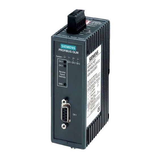
5 LED Indicators and Troubleshooting 5.1 LED Indicators 5 LED Indicators and Troubleshooting 5.1 LED Indicators PROFIBUS OLM LED indicators System CH 1 CH 2 CH 3 CH 2 CH 3 Receive Signal Intensity Fig. 16: LED indicators on the front plate LED Indicator Possible causes Signaling contact... - Page 35 5 LED Indicators and Troubleshooting 5.1 LED Indicators LED Indicator Possible causes Signaling contact lights yellow Signals are being received on the RS 485 bus line no signal electric not lit – Bus subscriber is not connected no signal – Connected bus subscriber is not switched on –...
-
Page 36: Troubleshooting
5 LED Indicators and Troubleshooting 5.2 Troubleshooting 5.2 Troubleshooting This chapter helps you to localize faults after they have been indicated (by LEDs or signal contacts). Please also refer to the description of the LED indicators in 5.1, p. 27. Fault indicated on the system LED See description of the LED indicators in 5.1, p. - Page 37 5 LED Indicators and Troubleshooting 5.2 Troubleshooting 2. Define the optical receiving level (see 4.4.7 ”Defining the receiving level of the optical ports“, p. 26 and 8.8 ”Measuring sockets“, p. 38): – Level is in the range ”Function is not guaranteed“. Check the optical fiber absorption using an optical level measuring device.
-
Page 38: Configuration
6 Configuration 6.1 Configuration of optical line and star topologies 6 Configuration During configuration, the PROFIBUS network parameter "Slot time" must be adapted to the network coverage, network topology and the data rate due to frame delays caused by lines and network components, as well as by monitoring mechanisms in the network components. - Page 39 Configuration 6.2 Configuration of redundant optical rings Data rate MBit/s 1651 MBit/s MBit/s 1.5 MBit/s kBit/s 187.5 kBit/s 3.75 93.75 kBit/s 1.875 45.45 kBit/s 0.909 19.2 kBit/s 0.384 kBit/s 0.192 Table 3a: Constants for calculating the slot time at DP standard (redundant optical ring) Data rate MBit/s...
-
Page 40: Technical Data
7 Technical Data 7 Technical Data OLM Module G11-1300 G12-1300 G12-EEC Voltage/power supply Operating voltage 18 V to 32 VDC, typ. 24 VDC, (redundant inputs uncoupled), safety extra-low voltage, indirect-coupled Current consumption max. 200 mA Output voltage/current for terminal 5 VDC + 5%, – 10% / 90 mA; short circuit-proof resistors (Pin 6 Sub-D socket) Signaling contact Maximum switch voltage... - Page 41 7 Technical Data OLM Module G11-1300 G12-1300 G12-EEC Transmission distance – with glass fiber E 10/125 – – 0 - 15 000 m (0.5 dB/km) – with glass fiber G 50/125 – 0 - 3 000 m 0 - 10 000 m (860 nm: 3.0 dB/km;...
-
Page 42: Appendix
SIMATIC NET PROFIBUS Networks Manual Declaration of In accordance with the above-named EC directive, the EC Declaration of Conformity Conformity can be viewed by the authorities responsible at: Siemens AG Bereich Automatisierungs- und Antriebstechnik Geschäftszweig Industrielle Kommunikation SIMATIC NET Postfach 4848 D-90327 Nürnberg... -
Page 43: C-Tick
8 Appendix 8.2 c-tick 8.2 c-tick Canada Canadian Notice This Class B digital apparatus complies with Canadian ICES-003. Avis Canadien Cet appareil numérique de la classe B est conforme à la norme NMB-003 du Canada. Australia This product meets the requirements of the AS/NZS 3548 standard. N117 8.3 FM approval FM 3611... -
Page 44: Literature Notes
8 Appendix 8.6 Literature notes 8.6 Literature notes – Manual SIMATC NET PROFIBUS Networks SIEMENS AG 6GK1970-5CA20-0AA0 (German) 6GK1 970-5CA10-0AA1 (English) 6GK1 970-5CA10-0AA2 (French) 6GK1 970-5CA10-0AA4 (Italian) – EN 50170-1-2 1996: „General Purpose Field Communication System“, Volume 2 „Physical Layer Spezification and Service Definition“... -
Page 45: Measuring Sockets
8 Appendix 8.8 Measuring sockets 8.8 Measuring sockets Signal quality Normal operation good Reduced optical system reserves critical Function not guaranteed poor Output voltage [mV] Diagram 1: Assignment of measured output voltage to signal quality. Notes: In order to attain a valid reading, it is necessary for the partner OLM at the other end of the optical fiber to send regular PROFIBUS frames. -
Page 46: Simatic Net - Support And Training
SIMATIC Training Centers We offer courses designed to enable you to familiarize yourself with the SIMATIC S7 automation system. Please contact your regional Training Center or the Central Training Center in 90327 Nuremberg, Germany. Internet: http://www.ad.siemens.de/training E-Mail: AD-Training@nbgm.siemens.de SIMATIC Customer Support Hotline Available worldwide 24 hours a day: Nuremberg (Nürnberg) - Page 47 +49 (911) 750-9991 E-Mail: juergen.hertlein@fthw.siemens.de Further support If you have any more questions about SIMATIC NET products, please contact your Siemens contact partner at your local or regional branch office. The addresses can be found – in our catalogue IK 10 –...