Siemens SIMATIC Equipment Manual
I/o device digital inputs
Hide thumbs
Also See for SIMATIC:
- Manual (648 pages) ,
- Operating instructions manual (182 pages) ,
- Operating manual (26 pages)
Table of Contents
Advertisement
Quick Links
Advertisement
Table of Contents

Related Manuals for Siemens SIMATIC


Summary of Contents for Siemens SIMATIC
- Page 2 I/O device digital inputs DI 16x24VDC M12-L 8xM12 (6ES7141-6BH00-0BB0) Preface ET 200eco PN M12-L Documentation Guide SIMATIC Product overview Wiring ET 200eco PN I/O device digital inputs Parameters/address space DI 16x24VDC M12-L 8xM12 (6ES7141-6BH00-0BB0) Interrupts/diagnostics alarms Equipment Manual Technical specifications...
- Page 3 Note the following: WARNING Siemens products may only be used for the applications described in the catalog and in the relevant technical documentation. If products and components from other manufacturers are used, these must be recommended or approved by Siemens. Proper transport, storage, installation, assembly, commissioning, operation and maintenance are required to ensure that the products operate safely and without any problems.
-
Page 4: Preface
Preface Purpose of the documentation This equipment manual supplements the ET 200eco PN M12-L Distributed I/O System (https://support.industry.siemens.com/cs/ww/en/view/109778292) system manual. Functions that relate in general to the distributed I/O devices ET 200eco PN M12-L are described in this system manual. - Page 5 Siemens' products and solutions undergo continuous development to make them more secure. Siemens strongly recommends that product updates are applied as soon as they are available and that the latest product versions are used. Use of product versions that are no longer supported, and failure to apply the latest updates may increase customers' exposure to cyber threats.
-
Page 6: Table Of Contents
Table of contents Preface ..............................3 ET 200eco PN M12-L Documentation Guide ..................6 Product overview ..........................10 Properties .......................... 10 Operator controls and display elements ................12 Wiring ..............................13 Terminal and block diagram ....................13 Pin assignment ........................14 Parameters/address space ........................ -
Page 7: Et 200Eco Pn M12-L Documentation Guide
This arrangement enables you to access the specific content you require. Basic information The system manual describes in detail the configuration, installation, wiring and commissioning of the SIMATIC ET 200eco PN M12-L distributed I/O system. The STEP 7 online help supports you in the configuration and programming. Device information... - Page 8 With the TIA Selection Tool, you can select, configure and order devices for Totally Integrated Automation (TIA). This tool is the successor of the SIMATIC Selection Tool and combines the known configurators for automation technology into one tool. With the TIA Selection Tool, you can generate a complete order list from your product selection or product configuration.
- Page 9 ET 200eco PN M12-L Documentation Guide SIMATIC Automation Tool You can use the SIMATIC Automation Tool to perform commissioning and maintenance activities simultaneously on various SIMATIC S7 stations as a bulk operation independent of TIA Portal. The SIMATIC Automation Tool provides a multitude of functions: •...
- Page 10 ET 200eco PN M12-L Documentation Guide SINETPLAN SINETPLAN, the Siemens Network Planner, supports you in planning automation systems and networks based on PROFINET. The tool facilitates professional and predictive dimensioning of your PROFINET installation as early as in the planning stage. In addition, SINETPLAN supports you during network optimization and helps you to exploit network resources optimally and to plan reserves.
-
Page 11: Product Overview
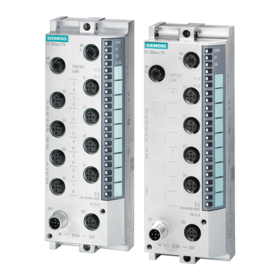
Product overview Properties Article number 6ES7141-6BH00-0BB0 View of the I/O device Figure 2-1 View of the I/O device DI 16x24VDC M12-L 8xM12 I/O device digital inputs DI 16x24VDC M12-L 8xM12 (6ES7141-6BH00-0BB0) Equipment Manual, 06/2021, A5E46570510-AB... - Page 12 Product overview 2.1 Properties Properties The I/O device has the following technical properties: • 16 digital inputs • M12 sockets for connection of sensors • 24 V DC supply voltage • Integrated switch with 2 ports • Configurable input delay 0.05 to 20 ms (per channel) •...
-
Page 13: Operator Controls And Display Elements
Product overview 2.2 Operator controls and display elements Operator controls and display elements The figure below shows the operator controls and display elements of the DI 16x24VDC M12-L 8xM12 I/O device. ① PN/MF (LAN): Sockets for connecting PROFINET ② RN/NS: RUN/network status LED ③... -
Page 14: Wiring
Wiring Terminal and block diagram The figure below shows an example of the pin assignment of signal inputs with 2-wire and 3-wire connection with single and dual assignment of the sockets. I/O device digital inputs DI 16x24VDC M12-L 8xM12 (6ES7141-6BH00-0BB0) Equipment Manual, 06/2021, A5E46570510-AB... -
Page 15: Pin Assignment
Wiring 3.2 Pin assignment ① Bus interface with integrated 2-port switch Supply voltage 1L+ (non-switched) ② DI circuit Ground 1M (non-switched) ③ Internal supply voltage Load voltage 2L+ (switched) ④ 2-wire connection (dual assignment of the Ground 2M (switched) socket) ⑤... - Page 16 Wiring 3.2 Pin assignment Pin assignment of the sockets for digital inputs The table below shows the pin assignment of the 8 sockets for the connection of digital inputs. Table 3- 2 Pin assignment for digital inputs Assignment Front view of the sockets X10 to X17 - sockets for digital inputs X10, X12, X11, X13,...
- Page 17 Wiring 3.2 Pin assignment Pin assignment of the connector for infeed of the supply voltage (M12 L-coded) The table below shows the pin assignment of the M12 L-coded connector for infeed of the supply voltage. Table 3- 3 Pin assignment of the supply voltage connector Assignment of the Assignment Front view of the...
-
Page 18: Parameters/Address Space
Parameters/address space Parameters The table below shows the parameters for the I/O device digital inputs DI 16x24VDC M12-L 8xM12. Table 4- 1 Configurable parameters and their defaults (GSD file) Parameters Value range Default Scope with configu- ration software, e.g. STEP 7 (TIA Portal) Diagnostics: Undervoltage 1L+ Disable Channel... -
Page 19: Explanation Of The Parameters
Parameters/address space 4.2 Explanation of the parameters Explanation of the parameters Diagnostics: Undervoltage 1L+ Enabling of diagnostics for insufficient supply voltage 1L+. Undervoltage at 1L+ triggers the "Undervoltage" maintenance event. You can find more information in section Maintenance events (Page 28). Diagnostics: Short-circuit Enabling of diagnostics for short-circuit to ground at transducer supply Diagnostics: Wire break detection and alarm... -
Page 20: Address Space
Parameters/address space 4.3 Address space Address space The DI 16x24VDC M12-L 8xM12 I/O device can be configured differently; see following table. Depending on the configuration, additional/different addresses are assigned in the process image input. Configuration options of the DI 16x24VDC M12-L 8xM12 I/O device You can configure the I/O device with STEP 7 (TIA Portal) or with a GSD file. - Page 21 Parameters/address space 4.3 Address space Value status (Quality Information, QI) The value status is always returned with the following configuration options: • DI 16x24VDC QI, • DI 16x24VDC MSI Evaluating the value status An additional two bytes are occupied in the input address space if you enable the value status for the I/O device.
- Page 22 Parameters/address space 4.3 Address space Address space for configuration as 1 x 16-channel DI 16x24VDC MSI With the configuration 1 x 16-channel I/O device (module-internal shared input, MSI), the channels 0 to 15 (incl. value status) of the I/O device are copied into a submodule. Channels 0 to 15 (incl.
- Page 23 4.3 Address space Reference You can find information on the functionality Module-internal Shared Input/Shared Output (MSI/MSO) in the STEP 7 online help or in the function manual SIMATIC PROFINET with STEP 7 (https://support.industry.siemens.com/cs/ww/en/view/49948856). I/O device digital inputs DI 16x24VDC M12-L 8xM12 (6ES7141-6BH00-0BB0)
-
Page 24: Interrupts/Diagnostics Alarms
Interrupts/diagnostics alarms Status and error displays LED displays The figure below shows the LED displays (status and error displays) of the I/O device DI 16x24VDC M12-L 8xM12. ① RN/NS: RUN/network status LED (green) ② ER/MS: ERROR/module status LED (red) ③ MT/IO: MAINT/IO status LED (yellow) ④... - Page 25 Interrupts/diagnostics alarms 5.1 Status and error displays Meaning of the LEDs The following tables set out the meaning of the status and error displays. Measures for dealing with diagnostics alarms can be found in the section Diagnostics alarms (Page 27). Behavior of the LEDs RN/NS (RUN/network status), ER/MS (ERROR/module status) and MT/IO (MAINT/IO status) on PROFINET Table 5- 1...
- Page 26 Interrupts/diagnostics alarms 5.1 Status and error displays P1 LK and P2 LK LEDs Table 5- 2 Error display of the P1 LK and P2 LK LEDs LEDs Meaning Solution P1 LK P2 LK There is no Ethernet connection between Check whether the bus cable to the the communications interface of your IO switch/communication partner is inter- device and a communication partner...
-
Page 27: Interrupts
Interrupts/diagnostics alarms 5.2 Interrupts Interrupts The I/O device digital inputs DI 16x24VDC M12-L 8xM12 supports diagnostic and hardware interrupts. Diagnostic interrupt The I/O device generates a diagnostic interrupt on the following events: • Wire break • Internal module fault • Parameter error •... -
Page 28: Alarms
Interrupts/diagnostics alarms 5.3 Alarms Alarms 5.3.1 Diagnostics alarms A diagnostics alarm is output for each diagnostics event. On the I/O device DI 16x24VDC M12-L 8xM12 the LED ER/MS flashes red. You can read out the diagnostics alarms in the diagnostics buffer of the CPU, for example. You can evaluate the error codes with the user program. -
Page 29: Maintenance Events
Interrupts/diagnostics alarms 5.3 Alarms 5.3.2 Maintenance events Triggering of a maintenance event The PROFINET interfaces of the ET 200eco PN M12-L support the diagnostic concept and maintenance concept in PROFINET according to the IEC 61158-6-10 standard. The goal is to detect and remove potential problems as soon as possible. -
Page 30: Hardware Interrupts
Interrupts/diagnostics alarms 5.3 Alarms 5.3.3 Hardware interrupts During a hardware interrupt, the CPU interrupts processing of the user program and processes the hardware interrupt organization block. For detailed information on the event, refer to the hardware interrupt organization block with the "RALRM"... -
Page 31: Technical Specifications
Technical specifications of the I/O device digital inputs DI 16x24VDC M12-L 8xM12 The following table shows the technical specifications as of the issue date. You can find a data sheet including daily updated technical specifications on the Internet (https://support.industry.siemens.com/cs/de/en/pv/6ES7141-6BH00-0BB0/td?dl=en). Article number 6ES7141-6BH00-0BB0... - Page 32 Technical specifications Article number 6ES7141-6BH00-0BB0 Encoder supply 24 V encoder supply Yes; Group-by-group for 2 channels, electronic • Short-circuit protection 100 mA; per output • Output current, max. Power loss Power loss, typ. 8.1 W Address area Address space per module 2 byte;...
- Page 33 Technical specifications Article number 6ES7141-6BH00-0BB0 Interface types Yes; 2x M12, 4-pin, D-coded • M12 port • Number of ports • integrated switch Protocols • PROFINET IO Device • Open IE communication Interface types M12 port • Autonegotiation • Autocrossing 100 Mbit/s •...
- Page 34 Technical specifications Article number 6ES7141-6BH00-0BB0 Interrupts/diagnostics/status information Alarms Yes; Parameterizable • Diagnostic alarm Yes; Parameterizable • Maintenance interrupt Yes; Parameterizable • Hardware interrupt Diagnoses • Diagnostic information readable • Monitoring the supply voltage – parameterizable Yes; DI, input current < 0.3 mA, per channel •...
- Page 35 Technical specifications Article number 6ES7141-6BH00-0BB0 Ambient conditions Ambient temperature during operation -40 °C • min. 60 °C • max. Altitude during operation relating to sea level Up to max. 5 000 m, at installation height > 2 000 • Ambient air temperature-barometric pressure- m additional restrictions altitude Connection method...
-
Page 36: A Dimension Drawing
Dimension drawing Dimension drawing The figure below shows the dimension drawing of the I/O device digital inputs DI 16x24VDC M12-L 8xM12 in front and side views. Figure A-1 Dimension drawing I/O device digital inputs DI 16x24VDC M12-L 8xM12 (6ES7141-6BH00-0BB0) Equipment Manual, 06/2021, A5E46570510-AB...