
Related Manuals for Denso HP3


Summary of Contents for Denso HP3
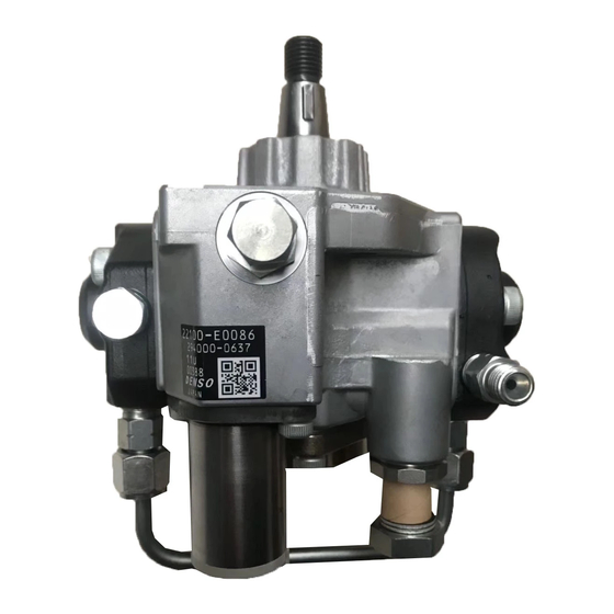
- Page 1 For DENSO Authorized ECD Service Dealer Only Diesel injection Pump SERVICE MANUAL Common Rail System Supply Pump (HP3) Overhaul Instruction Manual REPAIR October, 2005 00400553E...
- Page 2 –...
- Page 3 © 2005 DENSO CORPORATION All Rights Reserved. This book may not be reproduced or copied, in whole or in part, without the written permission of the publisher.
- Page 4 This manual describes the procedures for assembling and disassembling the supply pump (HP3) for the common rail type electronically controlled fuel injection system. Also, the proce- dures below are explained using a 294000-001# as a reference. If working on a different model of pump, be sure to verify the component parts against the parts list before beginning.
-
Page 5: Table Of Contents
Contents 1. Disassembly-Reassembly STT List --------------------------------------------------------------- 1 2. Disassembly Diagram -------------------------------------------------------------------------------- 4 3. Disassembly Outline ---------------------------------------------------------------------------------- 5 3.1 Securing the Supply Pump ------------------------------------------------------------------------------------------- 3.2 Removing the Pipes ---------------------------------------------------------------------------------------------------- 3.3 Removing the SCV (Suction Control Valve) ---------------------------------------------------------------------- 6 3.4 Removing the Feed Pump -------------------------------------------------------------------------------------------- 3.5 Removing the Fuel Temperature Sensor-------------------------------------------------------------------------- 3.6 Removing the Regulating Valve ------------------------------------------------------------------------------------- 3.7 Removing the Filter Sub-Assembly --------------------------------------------------------------------------------- 9... - Page 6 Revision History Date Revision Contents May. 2003 • First edition (publication code: QZZAD-09) January. 2004 • Publication code change from “QZZAD-09” to “00400237Z” September. 2005 • Publication code change from “00400237Z” to "00400553E” (refer to cover page) • "Removing the SCV (Suction Control Valve)","NOTE" added (p6: refer to 3.3 (2) ) •...
-
Page 8: Disassembly-Reassembly Stt List
1. Disassembly-Reassembly STT List Part Name DENSO P/N Exterior Appearance Nozzle Retaining Nut Wrench 95092-10500 QD0851 Pump Plate Assembly 95096-10620 * New STT QD0852 φ Coupling (Shaft Diameter 95095-20110 QD0853 Driver Chuck 95992-10130 QD0854 Hexagonal Bit (6mm) 95993-10040 QD0855 Hexagonal Bit (5mm) - Page 9 Part Name DENSO P/N Exterior Appearance Oil Seal Presser 95096-10240 QD0857 Oil Seal Remover 95096-10220 QD0858 Torque Wrench 95813-10010 QD0859 Torque Wrench 95813-10020 QD0860 Regulating Valve Socket Wrench 95096-10181 QD0861 Pipe 95092-11480 (Inner Diameter of Corresponding Parts φ φ 20 to...
- Page 10 Part Name DENSO P/N Exterior Appearance Filter Presser 95096-10630 * New STT QB0739 Camshaft Clearance Measurer 95092-10930 QD0074...
-
Page 11: Disassembly Diagram
2. Disassembly Chart This disassembly chart uses pump No. 294000-001# as a reference. When working on another model, please refer to the parts list. NOTE: To replace any part in this area, the entire assembly in the shaded area must be replaced. Element Assembly NOTE: Do not disassemble this portion. -
Page 12: Disassembly Outline
3. Disassembly Outline 3.1 Securing the Supply Pump (1) The pump plate assembly (STT) is secured in a vise. • STT: Pump Plate Assembly (95096-10620) QD0864 (2) Using two bolts, install the pump body on the pump plate assembly (STT). QD0865 QD0866 3.2 Removing the Pipes... -
Page 13: Removing The Scv (Suction Control Valve)
(2) Loosen the pipe nuts, and remove the pipes. NOTE: When loosening the nut, please use two spanners simultaneously. Q000017 QD0868 3.3 Removing the SCV (Suction Control Valve) (1) Using the hexagonal bit, remove the two hexag- onal bolts securing the SCV. •... -
Page 14: Removing The Feed Pump
(3) Remove the O-ring. NOTE: O-rings can not be reused. QD0871 3.4 Removing the Feed Pump (1) Remove the three hexagonal bolts on the feed pump cover. • STT: Hexagonal Bit (95093-10030) • STT: Driver Chuck (95992-10130) QD0872 QD0873 (2) Remove the feed pump rotor set. NOTE: Please keep the rotor set in the same condition (as a set). -
Page 15: Removing The Fuel Temperature Sensor
(3) Remove the feed pump plate. QD0875 (4) Remove the O-ring and two pins. NOTE: O-rings can not be reused. NOTE: When removing the O-ring, be careful not to damage the part's O-ring groove. (Please do not use sharp metal objects to remove.) O-Ring QD1851E 3.5 Removing the Fuel Temperature Sensor... -
Page 16: Removing The Regulating Valve
3.6 Removing the Regulating Valve (1) Using the regulating valve socket wrench (STT), remove the regulating valve. • STT: Regulating Valve Socket Wrench (95096-10181) NOTE: The regulating valve should only be removed when there is some sort of abnormality with the valve. -
Page 17: Removing The Element Sub-Assembly, Plunger, And Spring
QD0073 (2) Using the filter presser (STT), remove the filter sub-assembly from the filter plug. • STT: Filter Presser (95096-10630) NOTE: Once a filter sub-assembly is removed, do not reuse it. (Because of the danger of deformation of the O-ring or the plastic contact surface) QD0095 NOTE: Do not remove it unless it needs to be replaced. - Page 18 (2) Using the coupling (STT), rotate the drive shaft until it is directly opposite (180 degrees) from the element to remove. • STT: Coupling (95095-20110) Q000043E (3) Loosen the four hexagonal bolts on top of the element sub-assembly. • STT: Hexagonal Bit (95093-10040) •...
- Page 19 (5) Taking the plunger straight out of the element sub-assembly, remove the plunger and the spring. NOTE: As much as possible, avoid touching the polished parts of the plungers and the surfaces that contact the ring cam. Polished parts Q000042E (6) Remove three O-rings from pump body (or from the side of the element sub-assembly, if at- tached).
- Page 20 NOTE: Please secure it so that the vise will not touch the circled part at right. QD0889 (8) Loosen the three hexagonal bolts on top of the element sub-assembly. QD0890 NOTE: Loosen them uniformly in order as shown at right. QD1854 (9) Pull the element sub-assembly until it faces straight up and remove the element sub-as-...
-
Page 21: Element Sub-Assembly Foreign Particle Check
(10) Pull the element sub-assembly until it faces straight up and remove the element sub-as- sembly, plunger, and spring in the same way as step (5). NOTE: As much as possible, avoid touching the polished parts of the plungers and the surfaces that contact the ring cam. - Page 22 (2) Remove the key on top of the drive shaft. QD0894 (3) Turn the pump as shown at right and remove the pump plate assembly (STT) from the pump body. • STT: Pump Plate Assembly (95096-10620) QD0895 QD0896 (4) Loosen the six hexagonal bolts completely, which are partially loosened in step (1).
- Page 23 (5) Strike the drive shaft with a plastic hammer while holding down the pump body with one hand. NOTE: Make sure to use a plastic hammer. QD0898 NOTE: Be careful not to strike the pipe on the side of the drive shaft (circled at right). QD0899 QD0900 (6) Remove the drive shaft from the feed pump...
- Page 24 (7) Pull out the ring cam. NOTE: When removing the ring cam, be careful not to let it touch any surfaces which come in contact with the plunger (which has been polished). QD0902 (8) Remove the drive shaft. QD0903 (9) Remove the washer. QD0904 ADVICE: When removing the washer on the pump...
-
Page 25: Removing The Oil Seal
QD0906 3.11 Removing the Oil Seal (1) Using the oil seal remover (STT), remove the oil seal. • STT: Oil Seal Remover (95096-11220) Oil Seal Remover QD1855E QD0908... -
Page 26: Assembly Outline
4. Assembly Outline 4.1 Assembling the Oil Seal (1) Place the oil seal on the cover sub-assembly and use the oil seal presser (STT) to press it into the hydraulic press. • STT: Oil Seal Presser (95096-10240) NOTE: Once used, oil seals can not be reused. QD0909 4.2 Measuring the Drive Shaft Thrust (1) Install the washer on the cover sub-assembly. - Page 27 (4) Install the assembly from step (3) on the pump housing side. NOTE: Do not attach an O-ring to the cover sub- assembly at this time. QD0082 (5) Bolts are fastened to the cover sub-assembly in two places as shown at right. QD0083 (6) Install the camshaft clearance measurer (STT) to the drive shaft.
- Page 28 (7) Install the dial gauge on the camshaft clearance measurer. QD0077 (8) Pull the camshaft clearance measurer to set the dial gauge to 0. QD0079 (9) Press the camshaft clearance measurer in to measure the drive shaft thrust. • Normal: 0.35 ± 0.2mm NOTE: If the measurement does not meet the standard, replace the washer or cam shaft with...
-
Page 29: Assembling The Pump Body
4.3 Assembling the Pump Body (1) Install an O-ring to the cover sub-assembly. NOTE: Always use a new O-ring. QD0910 (2) Install the washer on the cover sub-assembly. QD0911 (3) Install a washer on the pump housing side as well. QD0912 (4) Install the ring cam to the drive shaft. - Page 30 (5) Install the parts (drive shaft and ring cam) as- sembled in step (4) to the pump housing. QD0914 QD0915 (6) Apply grease to the cover sub-assembly. QD0916 (7) Install the cover sub-assembly to the pump housing and partially tighten the six hexagonal bolts.
- Page 31 (8) With the pipe (STT) in the cover assembly, use the hydraulic press to press the cover sub-as- STT: Pipe sembly into the pump housing. • STT: Pipe (95092-11480) NOTE: Please perform this step so that the pipes protruding from the pump body do not touch the hydraulic press or the workbench.
-
Page 32: Assembling The Element Sub-Assembly, Plunger, And Spring
NOTE: Please tighten the six hexagonal bolts uniformly in the order shown at right. • Tightening Torque: 6.9 to 10.8 N·m (0.7 to 1.1 kgf·m) QD1858 4.4 Assembling the Element Sub-Assembly, Plunger, and Spring (1) Install the spring and plunger in the element sub-assembly. - Page 33 (4) While pressing the element sub-assembly down, uniformly tighten the four hexagonal bolts using the torque wrench (STT) and the hexagonal bit (STT). • STT: Torque Wrench (95813-10010) • STT: Hexagonal Bit (95993-10040) • STT: Driver Chuck (95992-10130) QD0926 NOTE: Please tighten the four hexagonal bolts uniformly in the order shown at right.
- Page 34 (6) Install the spring and plunger in the opposite side of the element sub-assembly. NOTE: As much as possible, avoid touching the polished parts. QD0929 (7) Install the element sub-assembly assembled in step (6) to the pump body. NOTE: Before installing, make certain that the contact point between the ring cam and the plunger (which has been polished) faces upwards.
-
Page 35: Installing The Regulating Valve
QD0932 4.5 Installing the Regulating Valve (1) Secure the pump as shown at right. (2) Install the regulating valve. O-Ring NOTE: • In cases where it is necessary to replace the regulating valve refer to p.9, "3.6 Removing the Regulating Valve" (Added Sept. 2005) •... -
Page 36: Installing The Filter Sub-Assembly
4.6 Installing the Filter Sub-Assembly (1) Using the filter presser, attach the filter sub-as- sembly. NOTE: When attaching, be careful not to tear the filter sub assembly mesh. QD0094 QD0095 QD0096 NOTE: Verify the new filter by sight. If there is by chance any foreign material in the filter, remove it with an air gun. -
Page 37: Installing The Fuel Temperature Sensor
(2) Using the hexagonal bit and the torque wrench (STT), install the filter plug. • Tool: Hexagonal Bit (8mm) • STT: Torque Wrench (95096-10020) • Tightening Torque: 14.8 to 22.8 N·m (1.5 to 2.3 kgf·m) QD0071 4.7 Installing the Fuel Temperature Sensor (1) Install the fuel temperature sensor. - Page 38 (2) Install position-holding pins in two places. QD0938 (3) Align the plate and the feed pump to the posi- tion-holding pins, and fasten them. QD0939 NOTE: Be careful about front and rear. The intake hole and exhaust hole should be visible. QD0940 (4) Install the feed pump key.
- Page 39 (5) Install the inner rotor. QD0942 NOTE: Please make sure the inner rotor key and the feed pump key are aligned. QD0943 (6) Install the outer rotor. NOTE: Please make sure the outer and inner rotor protrusions (circled at right) are aligned. QD0944 (7) Install an O-ring to the cover and the feed pump.
-
Page 40: Installing The Scv (Suction Control Valve)
(8) Align the cover and the feed pump to the posi- tion-holding pins, and fasten them. QD0946 (9) Using the torque wrench (STT) and the hexag- onal bit (STT), tighten the three hexagonal bolts. • STT: Torque Wrench (95813-10010) • STT: Hexagonal Bit (95993-10030) •... -
Page 41: Installing The Pipes
(3) Using the torque wrench (STT) and the hexag- onal bit (STT), tighten the two hexagonal bolts. • STT: Torque Wrench (95813-10010) • STT: Hexagonal Bit (95993-10030) • STT: Driver Chuck (95992-10130) • Tightening Torque: 6.9 to 10.8 N·m (0.7 to 1.1 kgf·m) QD0950 4.10 Installing the Pipe (1) Install the pipe. -
Page 42: Troubleshooting
5. Troubleshooting 5.1 Procedure Symptom (No: Check priority) Check method Judgment criterion Solution Check for fuel leaks to the Leak (See note below.) Replace the leak section. outside. Pump Measure the resistance assembly Does not meet the standard. (See the standard in the between the SCV termi- Replace the SCV. -
Page 43: Boundary Samples For Disassembly Checks
5.2 Boundary samples for disassembly checks Location Normal Abnormal Some degree Spark marks of contact from (black SCV terminal partner discoloring) on connector the connector surface Q000021 Q000022 Fine cracks Feed pump rotor Some degree of initial contact Q000023 Q000024 Feed pump plate Some degree Fine cracks... - Page 44 Location Normal Abnormal Main Lip Contact Oil Seal Small Wear Large Wear Width Width Q000622 Q000623 Main Lip Contact Camshaft Rough Surface Q000624 Q000625 Large wear width: approximately 1.5mm Small wear width (step wear) (Reference: approximately 1mm or less) Wear exists, but the contact width is small and the surface is good.
-
Page 45: Tightening Torque List
6. Tightening Torque List (Example: for 244000-001#) Unit: N·m Bolt ( Places) 15.68 - 23.52 Bolt ( Places) 6.9 - 10.8 Filter Plug 14.8 - 22.8 Bolt ( Places) Regulating Valve 6.9 - 10.8 7.9 - 11.8 Fuel Temperature Sensor 17.6 - 26.5 Retaining Nut 19 : 39.2 - 49.0... - Page 46 Published : May 2003 Second Issur: October 2005 Edited and published by: DENSO CORPORATION Service Department 1-1 Showa-cho, Kariya, Aichi Prefecture, Japan Printed in Japan ******...