Emerson AVENTICS System Description
Bus coupler aes/valve driver av
Hide thumbs
Also See for AVENTICS:
- Operating instructions manual (48 pages) ,
- Operating instructions manual (56 pages)
Table of Contents
Advertisement
Quick Links
Systembeschreibung | System description | Description du système
Descrizione del sistema | Descripción de sistema | Systembeskrivning
R412018139-BAL-001-AG
2020-11, Replaces: 2016-08
DE/EN/FR/IT/ES/SV
AVENTICS™ EtherNet/IP
Buskoppler AES/Ventiltreiber AV
Bus Coupler AES/Valve Driver AV
Coupleur de bus AES/Pilote de distributeurs AV
Accoppiatore bus AES/driver valvole AV
Acoplador de bus AES/controladores de válvula AV
Fältbussnod AES/Ventildrivenhet AV
Advertisement
Table of Contents

Related Manuals for Emerson AVENTICS


Summary of Contents for Emerson AVENTICS
- Page 1 Systembeschreibung | System description | Description du système Descrizione del sistema | Descripción de sistema | Systembeskrivning R412018139-BAL-001-AG 2020-11, Replaces: 2016-08 DE/EN/FR/IT/ES/SV AVENTICS™ EtherNet/IP Buskoppler AES/Ventiltreiber AV Bus Coupler AES/Valve Driver AV Coupleur de bus AES/Pilote de distributeurs AV Accoppiatore bus AES/driver valvole AV Acoplador de bus AES/controladores de válvula AV...
-
Page 2: Table Of Contents
Diagnostic Data ..........................................7.2.1 Cyclical diagnostic data of the electrical supply plate ............................7.2.2 Acyclic diagnostic data of the electrical supply plate ............................Parameter Data..........................................Structure of Pneumatic Supply Plate Data with UA‑OFF Monitoring Board ......................... AVENTICS™ EtherNet/IP | R412018139-BAL-001-AG | English... - Page 3 12.6 Conversion of the I/O Zone ....................................... 12.6.1 Permissible configurations ....................................12.6.2 Conversion documentation....................................12.7 New PlC Configuration for the Valve System ..................................13 Troubleshooting..........................................13.1 Proceed as Follows for Troubleshooting .................................... 13.2 Table of Malfunctions........................................14 Technical Data ........................................... AVENTICS™ EtherNet/IP | R412018139-BAL-001-AG | English...
-
Page 4: About This Documentation
2. Keep this documentation in a location where it is accessible to all users at all Failure to observe these notices may result in minor injuries or damage to times. property. 3. Always include the documentation when you pass the product on to third par- ties. AVENTICS™ EtherNet/IP | R412018139-BAL-001-AG | English... -
Page 5: Intended Use
The bus coupler connects I/O modules and valves to the EtherNet/IP fieldbus sys- • Follow all the instructions on the product. tem. The bus coupler may only be connected to valve drivers from AVENTICS and • Persons who assemble, operate, disassemble, or maintain AVENTICS products I/O modules from the AES series. -
Page 6: General Instructions On Equipment And Product Damage
The left side of the device contains The bus coupler has the following electrical connections: AVENTICS™ EtherNet/IP | R412018139-BAL-001-AG | English... -
Page 7: Led
The cable cross section must be designed according to the application. 4.1.2 LED The bus coupler has 6 LEDs. The table below describes the functions of the LEDs. For a comprehensive de- scription of the LEDs, see section g 11. LED Diagnosis on the Bus Coupler. AVENTICS™ EtherNet/IP | R412018139-BAL-001-AG | English... -
Page 8: Address Switch
Set the cycle time to the desired value. • Switch S2: The lower nibble of the last block of the IP address is set on switch S2. Switch S2 is labeled using the hexadecimal system from 0 to F. AVENTICS™ EtherNet/IP | R412018139-BAL-001-AG | English... -
Page 9: Configuring The Bus Coupler In The Fieldbus System
12 bytes The total length of the output data in the example configuration is 11 bytes. Of this, 10 bytes are the module output data and 1 byte is the bus coupler parame- ter byte. AVENTICS™ EtherNet/IP | R412018139-BAL-001-AG | English... -
Page 10: Setting The Bus Coupler Parameters
This section only describes the parameters for the bus coupler. The parameters of the I/O zone and the pressure regulators are explained in the system description AVENTICS™ EtherNet/IP | R412018139-BAL-001-AG | English... -
Page 11: Error-Response Parameters
Bus coupler diagnosis warning. Bit 1 The backplane of the valve zone issues an 5.6.2 Reading out the bus coupler diagnostic data error. The diagnostic data of the bus coupler can be read out as follows: AVENTICS™ EtherNet/IP | R412018139-BAL-001-AG | English... -
Page 12: Extended Diagnostic Data Of The I/O Modules
You will receive 1 data byte as a response. This byte contains the following infor- mation: • Byte 1 = 0x00: No error has occurred. • Byte 1 = 0x80: An error has occurred. Fig. 4: Valve position assignment AVENTICS™ EtherNet/IP | R412018139-BAL-001-AG | English... -
Page 13: Parameter Data
Address on delivery (explicit messages). On delivery, the switches are set to DHCP function (0x00). Switch S2 is set to 0 8.3 Parameter Data and switch S1 to 0. The electrical UA-OFF monitoring board does not have parameters. AVENTICS™ EtherNet/IP | R412018139-BAL-001-AG | English... -
Page 14: Manual Ip Address Assignment With Address Switch
0 (address assignment via As soon as the bus coupler has been added to the list and has sent the next DHCP server) DHCP request, the DHCP server will assign the specified address to the bus coupler. AVENTICS™ EtherNet/IP | R412018139-BAL-001-AG | English... -
Page 15: Commissioning The Valve System With Ethernet/Ip
Liquids and foreign objects could penetrate and destroy the device. 1. Make sure that the seals are integrated in the plug and not damaged. 2. Make sure that all plugs are mounted before starting the system. AVENTICS™ EtherNet/IP | R412018139-BAL-001-AG | English... -
Page 16: Conversion Of The Valve System
The valves from the AV series are always mounted on base plates that are assem- bled into blocks so that the supply pressure is applied to all valves. The base plates are always 2x or 3x base plates for two or three single or double solenoid valves. AVENTICS™ EtherNet/IP | R412018139-BAL-001-AG | English... -
Page 17: Transition Plate
24 V power supply - 10 % for all valves located to the right of the electrical supply plate via an integrated 4-pin M12 connection. The electrical supply plate monitors the additional power supply (UA) for undervoltage. AVENTICS™ EtherNet/IP | R412018139-BAL-001-AG | English... -
Page 18: Pressure Regulators
The electrical UA-OFF monitoring board monitors the actuator voltage UA for sta- tus UA < UA-OFF. All voltages are passed through directly. The UA-OFF monitor- ing board must therefore always be installed after an electrical supply plate to be monitored. AVENTICS™ EtherNet/IP | R412018139-BAL-001-AG | English... -
Page 19: Possible Combinations Of Base Plates And Cards
Fig. 16: Bus coupler rating plate Logo Series Mat. no. MAC address Power supply Manufacture date (FD) with format “FD: <YY>W<WW>” Serial number Country of manufacture Data Matrix code CE mark Internal plant ID AVENTICS™ EtherNet/IP | R412018139-BAL-001-AG | English... -
Page 20: Plc Configuration Key
3. Multiply this value by the number of inputs or outputs. This number is the the top of the device. length in bytes. The sequence of I/O modules starts on the left side of the bus coupler and ends Example: on the left end of the I/O zone. AVENTICS™ EtherNet/IP | R412018139-BAL-001-AG | English... -
Page 21: Conversion Of The Valve Zone
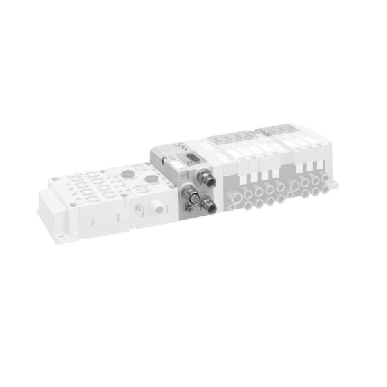
Integrated AV-EP circuit board Electrical supply plate Supply board Valve Section 1 Section 2 Section 3 Pressure supply Single pressure control working con- nection Power supply The valve system in Fig. 16 consists of three sections: AVENTICS™ EtherNet/IP | R412018139-BAL-001-AG | English... -
Page 22: Reviewing The Valve Zone Conversion
12.6.1 Permissible configurations No more than ten I/O modules may be connected to the bus coupler. If you cannot remedy a malfunction, please contact AVENTICS GmbH. For further information on converting the I/O zone, see the system descriptions The address is printed on the back cover of these instructions. -
Page 23: Technical Data
(connect and/or DIN EN 61000-6-2 “Electromagnetic compatibility” (Immunity for industrial environments) check EtherNet cable). DIN EN 61000-6-4 “Electromagnetic compatibility” (Emission standard for industrial envi- Neither a static nor a dynamic IP Assign IP address. ronments) address has been assigned. AVENTICS™ EtherNet/IP | R412018139-BAL-001-AG | English... - Page 24 Standards and directives DIN EN 60204-1 “Safety of machinery – Electrical equipment of machines – Part 1: General requirements” AVENTICS™ EtherNet/IP | R412018139-BAL-001-AG | English...