Table of Contents
Advertisement
Advertisement
Table of Contents

Related Manuals for MSI RX480M2 MS-7093


Summary of Contents for MSI RX480M2 MS-7093
- Page 1 RS480M2/RX480M2 MS-7093 (v1.X) M-ATX Mainboard English Version G52-M7093X8...
-
Page 2: Fcc-B Radio Frequency Interference Statement
Manual Rev: 1.6 Release Date: April 2005 FCC-B Radio Frequency Interference Statement This equipment has been tested and found to comply with the limits for a class B digital device, pursuant to part 15 of the FCC rules. These limits are designed to provide reasonable protection against harmful interference when the equipment is operated in a commercial environment. -
Page 3: Copyright Notice
If a problem arises with your system and no solution can be obtained from the user’s manual, please contact your place of purchase or local distributor. Alternatively, please try the following help resources for further guidance. Visit the MSI website for FAQ, technical guide, BIOS updates, driver updates, and other information: http://www.msi.com.tw/program/service/faq/ faq/esc_faq_list.php... -
Page 4: Safety Instructions
Safety Instructions Always read the safety instructions carefully. Keep this User’s Manual for future reference. Keep this equipment away from humidity. Lay this equipment on a reliable flat surface before setting it up. The openings on the enclosure are for air convection hence protects the equip- ment from overheating. -
Page 5: Table Of Contents
CONTENTS FCC-B Radio Frequency Interference Statement ............ii Revision History ....................... iii Technical Support ......................iii Safety Instructions ......................iv Chapter 1. Getting Started ..................1-1 Mainboard Specifications ..................1-2 Mainboard Layout ....................1-5 Packing Checklist ....................1-6 Chapter 2. Hardware Setup ................... 2-1 Quick Components Guide .................. - Page 6 PCI (Peripheral Component Interconnect) Slots ........2-18 PCI Interrupt Request Routing ..............2-18 Chapter 3. BIOS Setup ..................... 3-1 Entering Setup ...................... 3-2 Control Keys ....................3-2 Getting Help ....................3-3 The Main Menu ..................... 3-4 Standard CMOS Features ................... 3-6 Advanced BIOS Features ...................
- Page 7 Software Configuration ..................A-4 Sound Effect ....................A-4 Equalizer ....................... A-6 Speaker Configuration ................. A-7 Speaker Test ....................A-8 S/PDIF-Out ....................A-9 HRTF Demo ....................A-10 Microphone Effect ..................A-11 General ....................... A-12 Using 2-, 4- & 6- Channel Audio Function ............A-13 Appendix B: ATI SATA RAID Setup Guide ............
-
Page 8: Chapter 1. Getting Started
Getting Started Ch ap ter 1 . Get ti ng Started Getting Started Thank you for choosing the RS480M2/RX480M2 Series (MS- 7093 v1.X) Micro ATX mainboard. The RS480M2/RX480M2 Series ® ® mainboards are based on ATi RS480/RX480 & ATi SB400 chipsets ®... -
Page 9: Mainboard Specifications
† Supports 64-bit AMD ® Athlon 64 and Athlon 64 FX processor (Socket 939) † Supports up to 3500+, 3800+ Athlon 64 FX 53, or higher CPU (For the latest information about CPU, please visit http://www.msi.com.tw/pro- gram/products/mainboard/mbd/pro_mbd_cpu_support.php) Chipset † ATI ®... - Page 10 Getting Started MSI Reminds You... 1. Please note that users cannot install OS, either WinME or Win98, in their SATA hard drives. Under these two OSs, SATA can only be used as an ordinary storage device. 2. To create a bootable RAID volume for a Windows 2000 environment, Microsoft’s Windows 2000 Service Pack 4 (SP4) is required.
- Page 11 The 1394 GUID address is burnt in the BIOS core. If the 1394 GUID address is lost due to an unpredictable event, such as replac- ing a new BIOS chip, users can use the utility from MSI’s website by entering the 1394 GUID address to recover its original one.
-
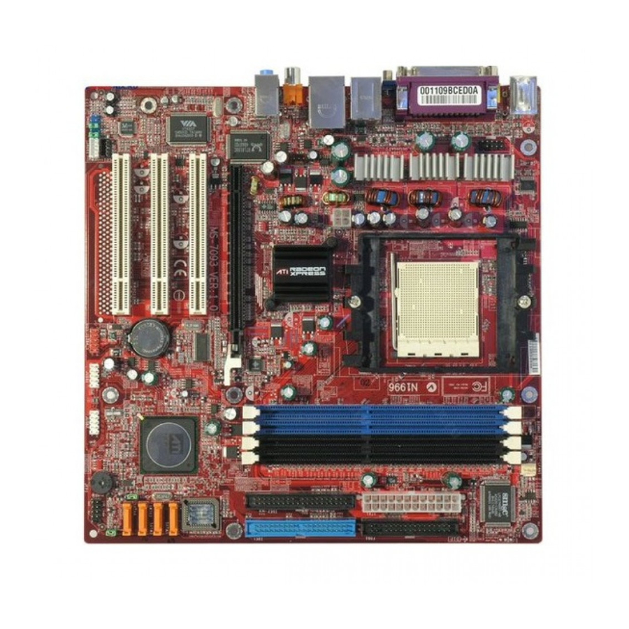
Page 12: Mainboard Layout
Getting Started Mainboard Layout CFAN1 Top: Mouse Bottom: Keyboard SMSC LPC47M997-NR COM1 (optional) Top: Parallel Port Bottom: Composite TV-Out (for RS480 S-Video (for RS480 VGA Port ( for RS480 T: 1394 Port (optional) B: USB Ports JPW1 T: LAN Jack B: USB Ports SFAN1 RS /RX480... -
Page 13: Packing Checklist
MS-7093 M-ATX Mainboard Packing Checklist MSI Driver/Utility CD SATA Cable (Optional) MSI motherboard Standard Cable for Standard Cable for Power Cable Floppy Disk IDE Devices 1394 Bracket (Optional) USB Bracket (Optional) Back IO Shield * The pictures are for refer- enc e only. -
Page 14: Chapter 2. Hardware Setup
Hardware Setup Chapter 2. Hardware Setup Hardware Setup This chapter tells you how to install the CPU, memory modules, and expansion cards, as well as how to setup the jumpers on the mainboard. Also, it provides the instructions on connecting the pe- ripheral devices, such as the mouse, keyboard, etc. -
Page 15: Quick Components Guide
MS-7093 M-ATX Mainboard Quick Components Guide JPW1, p.2-9 DDR DIMMs, p.2-7 CPU, p.2-3 SFAN1, p.2-11 CFAN1, p.2-11 COM1, p.2-15 Back Panel I/O, p.2-10 ATX1, p.2-9 FDD1, p.2-11 PCI Express IDE1/2, p.2-12 Slot, p.2-18 PCI Slots, p.2-18 SATA1~4, BATT p.2-13 JPWD1,p.2-17 JCMOS1, J1394_1, p.2-15 JAUD1, p.2-14... -
Page 16: Central Processing Unit: Cpu
If you do not have the heat sink and cooling fan, contact your dealer to purchase and install them before turning on the computer. For the latest information about CPU, please visit http://www.msi.com.tw/pro- gram/products/mainboard/mbd/pro_mbd_cpu_support.php. MSI Reminds You... -
Page 17: Cpu Installation Procedures For Socket 939
MS-7093 M-ATX Mainboard CPU Installation Procedures for Socket 939 1. Please turn off the power and unplug the power cord before Open Lever installing the CPU. Sliding 90 degree Plate 2. Pull the lever s ideways away from the socket. Make sure to raise the lever up to a 90-de- gree angle. -
Page 18: Installing Amd Athlon64 Cpu Cooler Set
MSI Reminds You... Mainboard photos shown in this section are for demonstration of the cooler installation for Socket 939 CPUs only. The appearance of your mainboard may vary depending on the model you purchase. - Page 19 Safety Hook Fixed Lever Fixed Bolt MSI Reminds You... While disconnecting the Safety Hook from the fixed bolt, it is neces- sary to keep an eye on your fingers, because once the Safety Hook is disconnected from the fixed bolt, the fixed lever will spring back...
-
Page 20: Memory
128MB~1GB 128MB~1GB 128MB~1GB Dual Channel MSI Reminds You... - The system operates ONLY when the DDR modules are installed in accordance with the above-mentioned memory population rules. - In dual-channel mode, make sure that you install memory modules of the same type and density on DDR DIMMs. -
Page 21: Installing Ddr Modules
MS-7093 M-ATX Mainboard Installing DDR Modules The DDR DIMM has only one notch on the center of module. The module will only fit in the right orientation. Insert the DIMM memory module vertically into the DIMM slot. Then push it in until the golden finger on the memory module is deeply inserted in the socket. -
Page 22: Power Supply
JPW1 Pin Definition JPW1 SIGNAL MSI Reminds You... 1. These two connectors connect to the ATX power supply and have to work together to ensure stable operation of the mainboard. 2. Power supply of 350 watts (and above) is highly recommended for system stability. -
Page 23: Back Panel
MS-7093 M-ATX Mainboard Back Panel L-In Parallel 1394 Port M ou se (Optional) L-Out Composite S-Video Keyboard VGA Port SPDIF-Out USB Ports TV-Out (for RS480) (for RS480) (for RS480) M ouse/Keyboard Connector USB Ports Pin5 Mouse/KBD Clock Pin6 NC SIGNAL -Data Pin4 VCC Pin3 GND... -
Page 24: Connectors
CPU fan control. SENSOR SENSOR +1 2V +1 2V CFAN1 SFAN1 MSI Reminds You... ® Please refer to the recommended CPU fans at AMD official website or consult the vendors for proper CPU cooling fan. 2-11... -
Page 25: Ata133 Hard Disk Connectors: Ide1 & Ide2
IDE2 (Secondary IDE Connector) IDE2 can also connect a Master and a Slave drive. MSI Reminds You... If you install two hard disks on cable, you must configure the second drive to Slave mode by setting its jumper. Refer to the hard disk docu- mentation supplied by hard disk vendors for jumper setting instructions. -
Page 26: Serial Ata Connectors: Sata1~Sata4
Serial ATA cable Take out the dust cover and connect to the hard disk devices Connect to SATA1/2/3/4 MSI Reminds You... Please do not fold the Serial ATA cable into 90-degree angle. Otherwise, data loss may occur during transmission. 2-13... -
Page 27: Cd-In Connector: Jcd1
Left channel audio signal to front panel AUD_RET_L Left channel audio signal return from front panel MSI Reminds You... If you don’t want to connect to the front audio header, pins 5 & 6, 9 & 10 have to be jumpered in order to have signal output directed to the rear audio ports. -
Page 28: Ieee 1394 Connectors: J1394_1 (Optional)
Hardware Setup Serial Port Header: COM1 (Optional) The mainboard offers one 9-pin header as serial port. The port is a 16550A high speed communication port that sends/receives 16 bytes FIFOs. You can attach a serial mouse or other serial device directly to it. Pin Definition SIGNAL DESCRIPTION... -
Page 29: Front Panel Connectors: Jfp1
USB1- USB0+ USB1+ JUSB1, JUSB2 (USB 2.0) Key (no pin) USBOC Connected to JUSB1 or JUSB2 USB 2.0 Bracket (Optional) MSI Reminds You... Note that the pins of VCC and GND must be connected correctly to avoid possible damage. 2-16... -
Page 30: Jumpers
JCMOS1 (Clear CMOS Jumper ) to clear data. JCMOS1 Keep Data Clear Data MSI Reminds You... To clear CMOS you should: 1. switch off the system and short 2-3 pin of the JCMOS1; 2. switch on the system again and the message “CMOS checksum error”... -
Page 31: Slots
MS-7093 M-ATX Mainboard Slots The motherboard provides one PCI Express x16 slot and three 32-bit PCI bus slots. PCI Express Slots The PCI Express slot, as a high-bandwidth, low pin count, serial, interconnect technology, supports Intel highest performance desktop platforms utilizing the Intel Pentium 4 processor with HT Technology. -
Page 32: Chapter 3. Bios Setup
SETUP. ² You want to change the default settings for customized features. MSI Reminds You... 1. The items under each BIOS category described in this chapter are under continuous update for better system performance. -
Page 33: Entering Setup
MS-7093 M-ATX Mainboard Entering Setup Power on the computer and the system will start POST (Power On Self Test) process. W hen the message below appears on the screen, press <DEL> key to enter Setup. Press DEL to enter SET UP If the message disappears before you respond and you still wish to enter Setup, restart the system by turning it OFF and On or pressing the RESET button. -
Page 34: Getting Help
BIOS Setup Getting Help After entering the Setup menu, the first menu you will see is the Main Menu. M ain M enu The main menu lists the setup functions you can make changes to. You can use the control keys ( ↑↓ ) to select the item. The on-line description of the highlighted setup function is displayed at the bottom of the screen. -
Page 35: The Main Menu
MS-7093 M-ATX Mainboard The Main Menu ® Once you enter Phoenix-Award BIOS CMOS Setup Utility, the Main Menu (Figure 1) will appear on the screen. The Main Menu allows you to select from twelve setup functions and two exit choices. Use arrow keys to select among the items and press <Enter>... - Page 36 BIOS Setup Load Fail-Safe Defaults Use this menu to load the default values set by the BIOS vendor for stable system performance. Load Optimized Defaults Use this menu to load the default values set by the mainboard manufacturer specifi- cally for optimal performance of the mainboard. Set Supervisor Password Use this menu to set Supervisor Password.
-
Page 37: Standard Cmos Features
MS-7093 M-ATX Mainboard Standard CMOS Features The items in Standard CMOS Features Menu are divided into several categories. Each category includes no, one or more than one setup items. Use the arrow keys to highlight the item and then use the <PgUp> or <PgDn> keys to select the value you want in each item. - Page 38 BIOS Setup items. Enter the information directly from the keyboard. This information should be provided in the documentation from your hard disk vendor or the system manufacturer. [Access Mode] The settings are [CHS], [LBA], [Large], [Auto]. [Capacity] The formatted size of the storage device. [Cylinder] Number of cylinders.
-
Page 39: Advanced Bios Features
MS-7093 M-ATX Mainboard Advanced BIOS Features CPU Internal Cache/External Cache Cache memory is additional memory that is much faster than conventional DRAM (system memory). W hen the CPU requests data, the system transfers the requested data from the main DRAM into cache memory, for even faster access by the CPU. The settings enable/disable the internal cache (also known as L1 or level 1 cache) and external cache (also known as L2 or level 2 cache). - Page 40 BIOS Setup First/Second/Third/Fourth Boot Device The items allow you to set the sequence of boot devices where BIOS attempts to load the disk operating system. Boot Up Floppy Seek Setting to [Enabled] will make BIOS seek floppy drive A: before booting the system. Settings: [Disabled], [Enabled].
- Page 41 MS-7093 M-ATX Mainboard MPS Version Control For OS This field allows you to select which MPS (Multi-Processor Specification) version to be used for the operating system. You need to select the MPS version supported by your operating system. To find out which version to use, consult the vendor of your operating system.
-
Page 42: Advanced Chipset Features
BIOS Setup Advanced Chipset Features MSI Reminds You... Change these settings only if you are familiar with the chipset. DRAM Configuration Press <Enter> to enter the submenu and the following screen appears. Timing M ode This field allows you to select the DDR timing setting. Setting to [Auto] enables M emclock Index Value (M hz) &... - Page 43 MS-7093 M-ATX Mainboard M emclock Index Value (M hz) User can place an artificial memory clock limit on the system. Please note that memory is prevented from running faster than this frequency. CAS# Latency (Tcl) This controls the CAS latency, which determines the timing delay (in clock cycles) before SDRAM starts a read command after receiving it.
- Page 44 BIOS Setup UMA Frame Buffer Size Frame Buffer is the video memory that stores data for video display (frame). This field is used to determine the memory size for Frame Buffer. Larger frame buffer size increases video performance. AGP Aperture Size This setting controls just how much system RAM can be allocated to AGP for video purposes.
-
Page 45: Integrated Peripherals
MS-7093 M-ATX Mainboard Integrated Peripherals South OnChip IDE Device Press <Enter> to enter the sub-menu and the following screen appears: IDE DMA Transfer Access This item is used to enable or disable the DMA transfer function of the IDE Hard Drive. - Page 46 BIOS Setup IDE Prefetch M ode The onboard IDE drive interfaces support IDE prefetching, for faster drive accesses. W hen you install a primary and/or secondary add-in IDE interface, set this option to [Disabled] if the interface does not support prefetching. Settings: [Enabled], [Disabled].
- Page 47 MS-7093 M-ATX Mainboard Super IO Device Press <Enter> to enter the sub-menu and the following screen appears: Onboard FDC Controller Select [Enabled] if your system has a floppy disk controller (FDD) installed on the system board and you wish to use it. If you install add-on FDC or the system has no floppy drive, select [Disabled] in this field.
- Page 48 BIOS Setup Init Display First This setting specifies which VGA card is your primary graphics adapter. Surroundv iew SURROUNDVIEW ™ provides the power and convenience of multi-adapter, multi- ® monitor support for computers that use an AGP- or PCI Express -based graphics card in conjunction with ATI integrated graphics processors (IGPs).
-
Page 49: Power Management Setup
MS-7093 M-ATX Mainboard Power Management Setup MSI Reminds You... S3-related functions described in this section are available only when your BIOS supports S3 sleep mode. ACPI Function This item is to activate the ACPI (Advanced Configuration and Power Management Interface) Function. If your operating system is ACPI-aware, such as Windows 98SE/ 2000/ME, select [Enabled]. - Page 50 BIOS Setup these modes: Suspend Mode and HDD Power Down. There are three options for power management: Min Saving Minimum Power Management. Suspend Mode=1 Hour Max Saving Maximum Power Management. Suspend Mode=1 Min User Define Allows end users to configure each mode separately. HDD Power Down If HDD activity is not detected for the length of time specified in this field, the hard disk drive will be powered down while all other devices remain active.
- Page 51 CPU temperature detecting function to prevent your CPU’s from overheating due to heavy workloads. Setting options: [Disabled], [Auto]. MSI Reminds You... To ensure stability of the Cool'n'Quiet function, it is always recom- mended to have the memory modules plugged in DIMM1.
-
Page 52: Pnp/Pci Configurations
BIOS Setup PNP/PCI Configurations This section describes configuring the PCI bus system and PnP (Plug & Play) feature. PCI, or Peripheral Component Interconnect, is a system which allows I/O devices to operate at speeds nearing the speed the CPU itself uses when communi- cating with its special components. - Page 53 MS-7093 M-ATX Mainboard IRQ Resources The items are adjustable only when Resources Controlled By is set to [Manual]. Press <Enter> and you will enter the sub-menu of the items. IRQ Resources list IRQ 3/4/5/7/9/10/11/12/14/15 for users to set each IRQ a type depending on the type of device using the IRQ.
-
Page 54: Pc Health Status
BIOS Setup PC Health Status This section shows the status of your CPU, fan, overall system status, etc. Monitor function is available only if there is hardware monitoring mechanism onboard. CPU/System Temperature, Current System/CPU Fan Speed These items display the current status of all of the monitored hardware devices/ components such as CPU voltages, temperatures and all fans’... -
Page 55: Load Fail-Safe/Optimized Defaults
MS-7093 M-ATX Mainboard Load Fail-Safe/Optimized Defaults The two options on the main menu allow users to restore all of the BIOS settings to the default Fail-Safe or Optimized values. The Optimized Defaults are the default values set by the mainboard manufacturer specifically for optimal perform- ance of the mainboard. -
Page 56: Set Supervisor/User Password
[System], the password is required both at boot and at entry to Setup. If set to [Setup], password prompt only occurs when you try to enter Setup. MSI Reminds You... About Supervisor Password & User Password: Supervisor password: Can enter and change the settings of the setup menu. -
Page 57: Chapter 4. Introduction To Digicell
MP3 files management and com- munication / 802.11g W LAN settings. Moreover, with this unique utility, you will be able to activate the MSI well-known features, Live Update and Core Center, which makes it easier to update the BIOS/drivers online, and to monitor the system hardware status (CPU/Fan tem- perature and speed) or to overclock the CPU/memory. -
Page 58: Main
Introduction: Click on each icon appearing above to enter the sub-menu to make further configuration. M SI Click on this button to link to MSI website: http://www.msi.com.tw. Quick Guide Click on this button and the quick guide of DigiCell will be displayed for you to review. - Page 59 Power on Agent In this sub-menu, you can configure date, time and auto-executed programs of the power-on, power-off and restarting features. MSI Reminds You... Click on back button in every sub-menu and it will bring you back to the main menu.
-
Page 60: H/W Diagnostic
In the H/W Diagnostic sub-menu, you can see the information, status and note of each DigiCell. You may double check the connection and installation of the item marked as gray. You may also click on the Mail to MSI button to send your questions or suggestions to MSI’s technical support staff. -
Page 61: Communication
Introduction to DigiCell Communication In the Communication sub-menu, you can see the status of all the LAN / W LAN / Bluetooth on the screen if the hardware is installed. The first icon indicates the onboard LAN on your system, the second icon indicates the wireless LAN status, and the third one is the information about the bluetooth on your system. -
Page 62: Software Access Point
MS-7093 M-ATX Mainboard M SI Feature Software Access Point In the Software Access Point sub-menu, you can see the communication status on your system and choose the desired software access point mode by clicking on the desired icon, in which the default settings are configured for your usage. The default software access point mode is set to WLAN Card M ode. -
Page 63: Access Point Mode
Introduction to DigiCell Access Point Mode Click on “Setting” button of the Access Point Mode and the following screen will display. IP Sharing Click on this icon to enable/disable the IP sharing. The default of this setting is disabled. Disabled. Enabled. -
Page 64: Wlan Card Mode
MS-7093 M-ATX Mainboard M SI Feature enable this feature, only PCs with MAC address located in Association Control List can connect to the wireless LAN. M AC Address MAC stands for Media Access Control. A MAC address is the hardware address of a device connected to a network. -
Page 65: Live Update
BIOS/drivers/VGA BIOS/VGA Driver/Utility online so that you don’t need to search for the correct BIOS/driver version throughout the whole Web site. To use the function, you need to install the “MSI Live Update 3” application. After the installation, the “MSI Live Update 3”... -
Page 66: Mega Stick
MS-7093 M-ATX Mainboard M SI Feature MEGA STICK In the MEGA STICK sub-menu, you can configure the settings of MSI MEGA STICK and the media files (*.m3u, *.mp3, *.wav, *.cda, *.wma) on your system. Basic Function Here you can edit your own play list with the buttons “load”, “save”, “delete”, “shuttle”, “repeat”... - Page 67 Introduction to DigiCell There is also a toolbar for you to execute some basic function, like play, stop, pause, previous/next song, song info and volume adjust. There is also a scroll bar on the top for you to forward/rewind. pause previous next forward/rewind...
-
Page 68: Non-Unicode Programs Supported
MS-7093 M-ATX Mainboard M SI Feature Non-Unicode programs supported If you are using an operating system in European languages, and you’d like to play the media files in MEGA STICK with East-Asian languages (such as Chinese, Japanese... etc.), it is possible that the file names display incorrectly. However, you can ins tall the Supplemental Language Support provided by Microsoft to solve this problem. - Page 69 Introduction to DigiCell 3. Then go to the [Advanced] tab and select the language you want to be supported (the language of the filename in the MegaStick) from the drop- down list in the [Language for non-Unicode programs], then click [Apply]. The system will install the necessary components from your Microsoft Setup CD immediately.
-
Page 70: Audio Speaker Setting
MS-7093 M-ATX Mainboard M SI Feature Audio Speaker Setting In the Audio Speaker Setting sub-menu, you can configure the multi-channel audio operation, perform speaker test, and choose the environment you prefer while en- joying the music. You can scroll the bar of each equalizer to regulate the current playing digital sound source. - Page 71 Introduction to DigiCell Click on the “Speaker test” button and the following dialogue box will appear: In this Speaker Configuration dialogue box, first select a desired multi-channel operation from the No. of Speakers pane. Then switch to the “Speaker Test” tab to test the connected speakers.
-
Page 72: Power On Agent
Click “OK” to restart the computer right away or click “Later” to restart your computer later. MSI Reminds You... Please note that the new setting will not take effect until you restart your computer. -
Page 73: Power Off / Restart
Delete. delete the added program MSI Reminds You... You can also enable the Every turn on function, which will enable the specified program(s) and file(s) every time the Digi Cell utility runs. -
Page 74: Auto Login
MS-7093 M-ATX Mainboard M SI Feature Auto Login Since the Power On function allows the system to power on automatically, you may have to enable this Auto Login function in the following situations: 1. If you are using a computer belonging to a domain in office, and you need to enter your user name &... -
Page 75: Appendix A: Using 2-, 4- & 6-Channel Audio Function
Using Audio Function Appendix A: Using 2-, 4- & 6-Channel Audio Function The mainboard is equipped with Realtek ALC658C chip, which provides support for 6-channel audio output, including 2 Front, 2 Rear, 1 Center and 1 Subwoofer channel. ALC658C allows the board to attach 4 or 6 speakers for better surround sound effect. -
Page 76: Installing The Audio Driver
2. Click Realtek AC97 Audio Driver. Clic k he r e MSI Reminds You... The AC97 Audio Configuration s o f t w a r e u t ilit y is u n d e r continuous update to enhance audio applications. Hence, the program screens shown here in this appendix may be slightly different from the latest software utility and shall be held for reference only. - Page 77 Using Audio Function 3 . Click Next to install the AC’97 Audio software. Clic k he r e 4 . Click Finish to restart the system. Se le ct this o ptio n Clic k he r e...
-
Page 78: Software Configuration
MS-7093 M-ATX Mainboard Software Configuration After installing the audio driver, you are able to use the 2-/4-/6-channel audio feature now. Click the audio icon from the window tray at the lower-right corner of the screen to activate the AC97 Audio Configuration. Sound Effect Here you can select a sound effect you like from the Environment list. - Page 79 Using Audio Function Here it provides the Karaoke function which will automatically remove human voice (lyrics) and leave melody for you to sing the song. Note that this function applies only for 2-channel audio operation. Just check the Voice Cancellation box and then click OK to activate the Karaoke function.
-
Page 80: Equalizer
MS-7093 M-ATX Mainboard Equalizer Here you regulate each equalizer for current playing digital sound sources. You may choose the provided sound effects, and the equalizer will adjust automatically. If you like, you may also load an equalizer setting or make an new equalizer setting to save as an new one by using the buttons Load and Save. -
Page 81: Speaker Configuration
Using Audio Function Speaker Configuration In this tab, you can easily configure your multi-channel audio function and speakers. First select a desired multi-channel operation from No. of Speakers. a. Headphone for the common headphone b. 2-Channel Mode for Stereo-Speaker Output c. -
Page 82: Speaker Test
MS-7093 M-ATX Mainboard Speaker Test You can use this tab to test each connected speaker to ensure if 4- or 6- channel audio operation works properly. If any speaker fails to make sound, then check whether the cable is inserted firmly to the connector or replace the bad speakers with good ones. -
Page 83: S/Pdif-Out
S/PDIF-Out In this tab you may slelect the format of SPDIF out. MSI Reminds You... 1. 6 speakers appear on the “Speaker Test” tab only when you select “6-Channel M ode” in the “Number of Speak ers” c olumn in “Speaker Configuration”... -
Page 84: Hrtf Demo
MS-7093 M-ATX Mainboard HRTF Demo In this tab you may adjust your HRTF (Head Related Transfer Functions) 3D positional audio before playing 3D audio applications like gaming. You may also select different environment to choose the most suitable environment you like. A-10... -
Page 85: Microphone Effect
Using Audio Function Microphone Effect In this tab you may add special effects to the connected microphone. A-11... -
Page 86: General
MS-7093 M-ATX Mainboard General In this tab it provides some information about the AC97 Audio Configuration utility, including Audio Driver Version, DirectX Version, Audio Controller & AC97 Codec. You may also select the language of this utility by choosing from the Language list. A-12... -
Page 87: Using 2-, 4- & 6- Channel Audio Function
Using Audio Function Using 2-, 4- & 6- Channel Audio Function In addition to a default 2-channel analog audio output function, the audio connectors on the Back Panel also provide 4- or 6-channel analog audio output function if a proper setting is made in the software utility. Read the following steps to have the Multi-Channel Audio Function properly set in the software utility, and have your speakers correctly connected to the Back Panel. - Page 88 MS-7093 M-ATX Mainboard n 4-Channel M ode for 4-Speaker Output The audio jacks on the back panel always provide 2-channel analog audio output function, however these audio jacks can be transformed to 4- or 6- channel analog audio jacks by selecting the corresponding multi-channel operation from No.
- Page 89 * Both Line In and MIC function are converted to Line Out function when 6-Channel Mode for 6-Speaker Output is selected. MSI Reminds You... While you are testing the speakers in 6-Channel Mode, if the sound coming from the center speaker and subwoofer is swapped, you should select Swap Center/Subwoofer Output to readjust these two channels.
-
Page 90: Appendix B: Ati Sata Raid Setup Guide
ATI SATA RAID Setup Guide Appendix B: ATI SATA RAID Setup Guide Two major challenges facing the storage industry today are (1): keep pace with increasing performance demands of computer systems by improving disk I/O throughput, and (2): provide data accessibility in the event of hard disk failure. To meet these two challenges, ATI south bridge SB400 supports four SATA ports and incorporates Silicon Image’s SiI 3112 Serial ATA host controller, together with Silicon Image’s Serial ATA RAID Management Software (SATARaid™). -
Page 91: Sata Raid Features
MS-7093 M-ATX Mainboard SATA RAID Features u RAID 0 and RAID 1 u On-line Mirror Rebuilding u RAID GUI Monitoring Utility: - Displays/Logs/Alerts Users to Vital RAID Set Information - Manages RAID Set Functions (configures, rebuilds, etc.) u RAID Set accommodates multiple size HDDs u HDDs function normally when not in RAID Sets u Adjustable stripe size for RAID 0 u Automatically selects highest available transfer speed for all ATA and ATAPI... -
Page 92: Disk Mirroring (Raid 1
ATI SATA RAID Setup Guide Disk Mirroring (RAID 1) Disk mirroring creates an identical twin for a selected disk by having the data simul- taneously written to two disks. This redundancy provides protection from a single disk failure. If a read failure occurs on one drive, the system reads the data from the other drive. -
Page 93: Creating Raid Sets
MS-7093 M-ATX Mainboard Creating RAID Sets Creating and deleting RAID sets and performing other RAID setting up operations are done in the BIOS. During bootup, a screen similar to the one below will appear for about 5 seconds. Press CTRL+S or the F4 key to enter the BIOS RAID Utility. The BIOS RAID Utility menu screen will appear. -
Page 94: Bios Raid Utility Screen Description
ATI SATA RAID Setup Guide BIOS RAID Utility Screen Description u M ain M enu The Main Menu in the upper left corner is used to choose the operation to be performed. The selections are: 1. Create RAID Set is used to create a new RAID Set (RAID 0 or RAID 1). 2. -
Page 95: Resolving Conflicts
MS-7093 M-ATX Mainboard strategy. RAID sets can be created either automatically, or to allow the greatest flexibility, manually. 1. Select “Create RAID Set.” 2. Choose a RAID 0 Striped, or a RAID 1 Mirrored set. 3. Select if you want the utility to Automatically Configure or if you want to manually configure the RAID Set. -
Page 96: Low Level Formatting
ATI SATA RAID Setup Guide 1. Select “Resolve Conflicts” 2. Select the “Invalid RAID drive” entry in the Logical Drive Status window and press Enter. 3. Follow the prompts to resolve the conflict. Note that some conflict resolutions may result in the drive letter assignment changing; for example the RAID set may have been drive D: but after the conflict resolution, it may become drive E:. -
Page 97: Installing Raid Drivers (For W Indows 2000/Xp Only
MS-7093 M-ATX Mainboard Installing RAID Drivers (for Windows 2000/XP only) Installing RAID Drivers during OS Install Follow the instructions in this section if you are performing a new installation of the OS (W indows 2000/XP), and wish to boot from a RAID drive connected to the SATA controller. - Page 98 ATI SATA RAID Setup Guide T he following screen shots are taken from the AT I driv er installation wizard.
- Page 99 MS-7093 M-ATX Mainboard B-10...
-
Page 100: Installing Sataraid Utility
ATI SATA RAID Setup Guide Installing SATARaid Utility Insert your W indows 2000/XP ATI driver CD into the CD-ROM/DVD drive. Run the setup.exe program on the CD and follow the setup instructions to complete the installation. The following screen shots are taken from the installation of SATARaid. B-11... - Page 101 MS-7093 M-ATX Mainboard SATARaid GUI can be launched from the Task Bar B-12...
-
Page 102: Sataraid Gui
ATI SATA RAID Setup Guide SATARaid GUI The SATARaid GUI offers the user the ability to easily monitor the RAID Set. To launch the GUI, simply double-click on the icon located in the bottom right hand corner of the Desktop. If the icon does not appear in the bottom right hand corner of the desktop, find where the SATARaid application was saved and launch from there. - Page 103 MS-7093 M-ATX Mainboard A RAID 1 Set Monitoring Example B-14...
- Page 104 ATI SATA RAID Setup Guide B-15...
- Page 105 MS-7093 M-ATX Mainboard B-16...
- Page 106 ATI SATA RAID Setup Guide A RAID 0 Set Monitoring Example B-17...
- Page 107 MS-7093 M-ATX Mainboard B-18...
- Page 108 ATI SATA RAID Setup Guide B-19...
- Page 109 MS-7093 M-ATX Mainboard B-20...
- Page 110 ATI SATA RAID Setup Guide B-21...
- Page 111 MS-7093 M-ATX Mainboard B-22...
- Page 112 ATI SATA RAID Setup Guide B-23...
-
Page 113: Configuring Raid 0 Set(S) With Windows Disk Manager
MS-7093 M-ATX Mainboard Configuring RAID 0 Set(s) with Windows Disk Manager Note: This section is only applicable to non-initiated drives. It is not applicable if the drives have been set up as RAID 0 with the BIOS utility. The W indows XP built-in Disk Manager can be used to set up installed SATA drives in Disk Striping (RAID 0) configuration. - Page 114 ATI SATA RAID Setup Guide If SATA drives had not been initialized, initialize the disk as Dynamic. Right click on Disk 0 and select ‘New Volume’. At ‘New Volume W izard’ select Striped for type of volume. B-25...
- Page 115 MS-7093 M-ATX Mainboard Total size of disk set for striping is set next. B-26...
- Page 116 ATI SATA RAID Setup Guide B-27...
- Page 117 MS-7093 M-ATX Mainboard B-28...
-
Page 118: Appendix C: Ati Surroundview
ATI SURROUNDVIEW Appendix C: ATI SURROUNDVIEW ATI SURROUNDVIEW ™ is an integrated feature supported by the onboard ATI northbridge chipset. It provides the power and convenience of multi-adapter, multi- ® monitor support for computers that use an AGP- or PCI Express -based graphics card in conjunction with specific ATI integrated graphics processors (IGPs). -
Page 119: Getting Started
MS-7093 M-ATX Mainboard Getting Started SURROUNDVIEW ™ provides the power and convenience of multi-adapter, multi- monitor support for computers that use an AGP- or PCI Express®-based graphics card in conjunction with the following ATI integrated graphics processors (IGPs): u RADEON ®... -
Page 120: System Requirements
ATI SURROUNDVIEW System Requirements Supported ATI Products Integrated graphics processors (enabled by system BIOS): ® • RADEON XPRESS 200 ® • RADEON 9100 Pro ® • RADEON 9100 IGP ® • RADEON 9000 IGP AGP/PCIe™ graphics cards: ® • RADEON X800 series ®... -
Page 121: Installing A Graphics Card
MS-7093 M-ATX Mainboard Installing a Graphics Card MSI Reminds You... This section provides generic installation instructions only. In most c a s es a g rap hic s c a rd will c o me with sp eci fic in s ta llation instructions, in which case users should consult their graphics card manual and follow the instructions therein. - Page 122 ATI SURROUNDVIEW 4. Unscrew or unfasten and remove any existing graphics card from your computer. 5. Locate the appropriate slot and, if necessary, remove the metal back-plate c over. 6. Align your graphics card with the slot and press it in firmly until the card is fully seated.
-
Page 123: Enabling Surroundview
MS-7093 M-ATX Mainboard Enabling SURROUNDVIEW Enabling the Integrated Graphics Processor In order to use SURROUNDVIEW ™, the integrated graphics processor (IGP) on the motherboard must be enabled in addition to the graphics card in the PCIe™ slot. Make sure the IGP is enabled (using the BIOS setup utility) in addition to the graphics card before continuing. -
Page 124: Frequently Asked Questions
ATI SURROUNDVIEW 6. Use the arrow keys to navigate to Integrated Peripherals, and then press Enter. The Integrated Peripherals screen appears. 7. Use the arrow keys to navigate to Init Display First and set it to PCI-E. 8. Use the arrow keys to navigate to Surroundview and set it to Enabled. 9. -
Page 125: Using Multiple Displays
MS-7093 M-ATX Mainboard Using Multiple Displays Setting Up Multiple Displays To use SURROUNDVIEW ™, connect display devices to the output connections of both your integrated graphics processor (IGP) and your PCI Express® graphics card. There will normally be three connections: one from the IGP and two from the graphics card. - Page 126 ATI SURROUNDVIEW u To set up a multi-monitor display 1. Right-click on a clear area of your desktop and choose Properties. The Display Properties dialog opens. 2. Select the Settings tab. 3. Click the Identify button to display a large number on each monitor. 4.
-
Page 127: Using Surroundview
MS-7093 M-ATX Mainboard Using SURROUNDVIEW Business Applications Using SURROUNDVIEW ™, you can run multiple applications simultaneously — for example, a spreadsheet, a W eb browser and a stock trader could be run and viewed on separate screens at the same time. u To enable SURROUNDVIEW™... - Page 128 ATI SURROUNDVIEW 3. Open your W eb browser, and then drag it to monitor 2. Web browser displayed on monitor 2 4. Launch another instance of your W eb browser, and then drag it to monitor 3. Another Web browser displayed on monitor 3 C-11...
-
Page 129: Games
Using SURROUNDVIEW ™, you can display a different Flight Simulator view on each of your monitors. MSI Reminds You... For best results, in the Flight Simulator Settings Display dialog, set the full screen resolution for each video adapter to match the desktop resolution for the corresponding display. - Page 130 ® Microsoft Flight Simulator with both Primary and Monitor 2 running MSI Reminds You... 1. When moving a 3D window, you may see some hesitation when crossing the boundary to a secondary display. After you move the 3D window to the secondary display, that scene will be displayed in 3D.
- Page 131 MS-7093 M-ATX Mainboard 4. From the Views menu, create another new window, and then drag it to monitor 3. ® Microsoft Flight Simulator using all three monitors C-14...