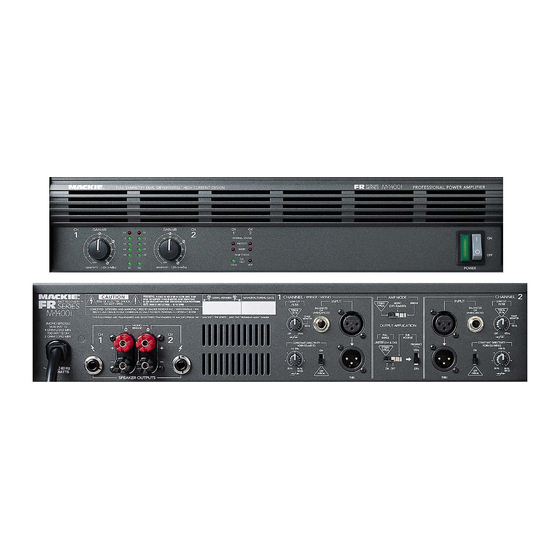
Mackie FR Series Service Manual
Hide thumbs
Also See for FR Series:
- Owner's manual (43 pages) ,
- Owner's manual (44 pages) ,
- Hook-up manual (4 pages)
Summary of Contents for Mackie FR Series
- Page 1 Service Bulletins M1400, M1400i FR series amplifiers (series II) SERVICE MANUAL 2000 MACKIE DESIGNS, INC.
- Page 2 SERVICE ON THIS EQUIPMENT IS TO BE PERFORMED BY EXPERIENCED REPAIR TECHNICIANS ONLY...
-
Page 3: Table Of Contents
• What’s all this “series II” stuff anyway? The designation “series II” is an internal Mackie way of describing the new M1400 and M1400i amplifiers built after June 1999. You will not see “series II” written on any of the advertising, boxes or silkscreens. -
Page 4: Overview
Overview M1400 and M1400i power amps built after June 15, 1999 have some rather lovely improvements. These include: 1. Higher output fan for increased cooling – The old fan which has an output of 51 CFM has been replaced with a new hi-performance Panasonic FBA0824H1T fan that has 62 CFM output. -
Page 5: Safety Test
Safety test You must perform the following leakage test before returning the unit to your customer. Take every safety precaution to protect yourself while doing this test. 1. Make a small loading RC circuit as shown in the diagram below, and connect the AC volt meter between the AC power source ground and any exposed metal on the unit under test. -
Page 6: Parts
M1400, M1400i series II PARTS LIST PART# DESCRIPTION PAGES Parts Numbering guide 040- Cables 090-137-XX M1400 assembly 055- Finished PCB Assy 080-149-00 Heatsink subassembly 090-134-00 M1400i assembly 100- Pots and resistors 080-143-00 Heatsink subassembly 200- Capacitors 055-253-00 Input board 300- Semiconductors 055-254-00 Display board 400- Jacks/Connectors 055-255-00 Amplifier board... - Page 7 M1400, M1400i series II Master Parts List 090-137-XX M1400 series II Part # Description 090-137-00 M1400 SERIES II 120V A6 A2 1 090-137-01 M1400 SERIES II 230V A6 A2 1 090-137-02 M1400 SERIES II 100V A6 A2 1 040-359-00 RIB 28GA 20C 4.25IN PLZD 040-360-00 RIB 28GA 20C 18IN PLZD 055-162-01...
- Page 8 M1400, M1400i series II Heatsink sub assy 080-149-00 Part # Description 080-149-00 SA HTSK M1400 SERIES II A6 A2 1 040-209-00 RIB 28GA 10C 11.5 PLZD 055-255-01-01 PCB ASSY MAIN M1400 A6 A2 1 SEE PAGE 8. THIS HAS SPEAKON OUTPUTS 220-059-00 LYT 12000UF 20% 82V 35X60 NOTE THAT THIS IS 12,000 UF...
- Page 9 M1400, M1400i series II Master Parts List 090-134-00 M1400i series II, 120v Part # Description 090-134-00 M1400-I SERIES II 120V A6 A2 1 040-359-00 RIB 28GA 20C 4.25IN PLZD 040-360-00 RIB 28GA 20C 18IN PLZD 055-253-00-01 PCB ASSY INPUT A2 A2 1 SEE PAGE 6 055-254-00-01 PCB ASSY DISPLAY...
- Page 10 M1400, M1400i series II Heatsink sub assy 080-143-00 Part # Description 080-143-00 SA HTSK M1400-I SERIES II A6 A2 1 040-209-00 RIB 28GA 10C 11.5 PLZD 055-255-02-01 PCB ASSY MAIN M1400-I A6 A2 1 SEE PAGE 8. THIS HAS 1/4” OUTPUTS 220-058-00 LYT 10000UF 20% 82V 35X60 NOTE THAT THIS IS 10,000 UF...
- Page 11 253a M1400, M1400i series II 055-253-00 Rev A Input board Part # Description Value Reference 040-136-00 DIS 18GA 1007 BLK 5 QDTRM 130-037-02 RESISTOR POT 9MM HORIZ 10K C R22 R33 130-062-02 POT 50KC 12MM DUAL WO SLV 50KC R13 R24 140-025-00 RESISTOR CF 140-078-00...
- Page 12 254a M1400, M1400i series II 055-254-00 Rev A Display board Part # Description Value Reference 130-070-00 POT RTY 5K LIN 9MM 21DET R2 R32 140-057-00 RESISTOR CF 140-068-00 RES TF SM .1W 5% 620 OHM R9 R20 140-073-00 RES TF SM .1W 5% 1K0 OHM R33 R38 140-076-00 RESISTOR CF...
- Page 13 255a M1400, M1400i series II 055-255-xx Rev A Amplifier board Part # Description Value Reference 040-135-00 CABLE ASSY, 18AWG, GN/YW, 4” 100-001-00 RESISTOR CF R57 R72 R75 R89 100-017-00 RESISTOR CF R60 R69 R78 R86 R208 R213 100-023-00 RESISTOR CF R58 R61 R67 R70 R76 R79 R84 R87 100-027-00 RESISTOR CF...
- Page 14 255a M1400, M1400i series II Part # Description Value Reference 200-023-00 CAPACITOR, POLY BOX 1000pF 20% C77 C84 200-024-00 CAPACITOR, POLY BOX .01uF C49 C53-54 200-036-00 CAPACITOR, METALIZED POLY .1uF C19 C26-28 200-044-02 PLY FILM 270PF 5% 630V TR 270pF 5% C21-23 C25 210-001-02 CAPACITOR CERAMIC TAPE...
- Page 15 255a M1400, M1400i series II ..amplifier continued Part # Description Value Reference 400-133-00 HEADER, 2X3, MATE-N-LOCK 600V 400-143-00 CONN, HDR, 3-PIN, UN-SHROUDED, 0 .100 J20 J37 400-166-00 CONNECTOR JACK 1/4” TRS HORIZ, PC MNT J43 J45 (M-1400i ONLY) 400-171-00 CONN, HDR, 2-PIN, UN-SHROUDED,0 .100 J2-3 400-173-00 CONN QUICK DISC .250 W/STABLE-LOK TABS...
- Page 16 162a M1400, M1400i series II 055-162-xx Rev A Soft Start board Part # Description Value Reference 055-162-01 PCB ASSY SOFT START 240V FOR 240VAC 055-162-02 PCB ASSY SOFT START 100V FOR 100VAC 100-068-00 RESISTOR CF .125W R5-8 100-080-00 RESISTOR CF .125W 123-124-00 RESISTOR MOF...
- Page 17 FR series Amplifier ribbon replacement instructions (NEW! IMPROVED! July 2000) Models affected: FR series M1200, M1400, M1400i M1200: All models. M1400i: Before Serial # DA20889 and all models with “AM” prefix. M1400 and 230v versions: Before Serial # DB12700 and all models with “AH” prefix.
-
Page 18: Input Board
THE MACKIE FIXER • MACKIE DESIGNS SERVICE NEWS Procedure continued. Input board work: If the two ribbon cables are soldered to the input board, follow steps 7 to 11. If not, then go to step 12. Remove the metal shield plate and insulator sheet from the back of the input board.


