Table of Contents
Advertisement
Quick Links
Advertisement
Table of Contents

Related Manuals for Elation KL PANEL XL


Summary of Contents for Elation KL PANEL XL
- Page 1 KL PANEL XL User Manual...
- Page 2 Elation Professional B.V. | Junostraat 2 | 6468 EW Kerkrade, The Netherlands +31 45 546 85 66 | +31 45 546 85 96 fax | www.elationlighting.eu | info@elationlighting.eu Elation Professional Mexico | AV Santa Ana 30 | Parque Industrial Lerma, Lerma, Mexico 52000 +52 (728) 282-7070 DOCUMENT VERSION Due to additional product features and/or enhancements, an updated version of this document may be available online.
-
Page 3: Table Of Contents
CONTENTS General Information Limited Warranty Safety Guidelines Maintenance Guidelines Fixture Overview Installation Instructions Fixture Installation Accessory Installation Battery Connection System Menu Manual Mode DMX Channel Functions and Values Color Temperature Table Virtual Swatch Book Refresh Rate Table Dimmer Modes Specifications Dimensional Drawings Optional Accessories | FCC Statement... -
Page 4: General Information
Junior Pin (x1) Power Cable (x1) Barndoor Safety Cable (x1) CUSTOMER SUPPORT Contact ELATION Service for any product related service and support needs. Also visit forums.elationlighting.com with questions, comments, or suggestions. ELATION SERVICE USA - Monday - Friday 8:00am to 4:30pm PST 323-582-3322 | Fax 323-832-9142 | support@elationlighting.com... -
Page 5: Limited Warranty
The sole responsibility of Elation Professional under this warranty shall be limited to the repair of the product, or replacement thereof, including parts, at the sole discretion of Elation Professional. All products covered by this warranty were manufactured after January 1, 1990, and bare identifying marks to that effect. -
Page 6: Safety Guidelines
This fixture is a sophisticated piece of electronic equipment. To guarantee smooth operation, it is important to follow all instructions and guidelines in this manual. Elation Professional is not respon- sible for injury and/or damages resulting from the misuse of this fixture due to the disregard of the information printed in this manual. - Page 7 SAFETY GUIDELINES • DO NOT TOUCH the fixture housing during operation. • Turn OFF the power and allow approximately 15 minutes for the fixture to cool down before serving. • DO NOT shake fixture and avoid brute force when installing and/or operating fixture. • DO NOT operate fixture if the power cord is frayed, crimped, damaged, and/or if any of the power cord connectors are damaged and do not insert into the fixture securely with ease.
-
Page 8: Maintenance Guidelines
Regular inspections are recommended to ensure proper function and extended life. There are no user serviceable parts inside this fixture. Please refer all service issues to an authorized Elation ser- vice technician. Should you need any spare parts, please order genuine parts from an authorized Elation dealer. -
Page 9: Fixture Overview
FIXTURE OVERVIEW... -
Page 10: Installation Instructions
INSTALLATION INSTRUCTIONS FLAMMABLE MATERIAL WARNING Keep fixture minimum 5.0 feet (1.5m) away from flammable materials and/or pyrotech- nics. ELECTRICAL CONNECTIONS A qualified electrician should be used for all electrical connections and/or installations. DO NOT PERFORM THE INSTALLATION YOURSELF IF YOU ARE NOT QUALIFIED TO DO SO! WHEN RUNNING ON 110V POWER, THE UNITS MAY NOT BE LINKED TOGETHER VIA THE POWER INPUT/OUTPUT TERMINALS! EACH UNIT MUST BE INDEPENDENTLY CONNECTED... -
Page 11: Fixture Installation
FIXTURE INSTALLATION CLAMP INSTALLATION A junior pin can be attached to the mounting surface on the fixture’s mounting yoke, and this junior pin can then be used as an attachment point for a mounting clamp. Details on junior pin installation can be found in the Accessory Installation section of this manual. -
Page 12: Accessory Installation
ACCESSORY INSTALLATION JUNIOR PIN INSTALLATION To install the junior pin to the mounting point on the yoke, orient the junior pin with the notched end facing the yoke mounting point. Align the notch on the junior pin with the matching groove on the yoke mounting point. - Page 13 ACCESSORY INSTALLATION STAND MOUNT INSTALLATION This device is capable of being stand mounted by following the steps below: 1. Install the Junior Pin, as detailed elsewhere in this section. 2. Lock the mounting bracket in place by tightening both bracket knobs. 3.
- Page 14 ACCESSORY INSTALLATION BARN DOOR INSTALLATION 1. Unlock both frame lock tabs using the latches located on each tab (circled in the image below). Flip the top edge of the frame upward. 2. Look beneath the frame lock tabs and locate the installation slots on the inner edge of the frame. The slot closest to the front of the device should be vacant.
-
Page 15: Battery Connection
BATTERY CONNECTION This device is capable of receiving power from a battery pack. NOTICE: The user is responsible for ensuring compatibility between the device and the bat- tery pack. Always ensure that the output specifications, operating conditions, and connection pinouts of the battery pack match the device requirements. The device features a 4-pin XLR connector for battery power. -
Page 16: System Menu
SYSTEM MENU The fixture includes an easy to navigate system menu. The control panel (see image below) located on the back of the fixture provides access to the main system menu, where all necessary system adjustments are made. During normal operation, pressing the MODE button once will access the fixture’s main menu. - Page 17 SYSTEM MENU ELATION KL Panel XL - System Menu Supports Software Versions: 1.07 Displays currently HOME INTERFACE xx CH xxxx selected DMX SHOW ADDR: 001 mode Select to run fixture Disabled in DMX control mode Select to run fixture Int CCT GRN...
- Page 18 SYSTEM MENU ELATION KL Panel XL - System Menu Supports Software Versions: 1.07 0% - 100% Dimmer 2000K - 10000K STANDALONE Default = 0% Green Shift -100% - +100% Color01 - Color53 Virtual Color Primary On / Off On / Off...
- Page 19 SYSTEM MENU ELATION KL Panel XL - System Menu Supports Software Versions: 1.07 Display returns to Display Screen 10s - 5min home screen after (default = 1min) Delay 30s of inactivity Display Display Screen Off, 10s - 5min Lock Yes / No / Auto...
-
Page 20: Manual Mode
MANUAL MODE ENCODER KNOB DESIGNATIONS INT CCT GRN (INTENSITY, COLOR TEMPERATURE, GREEN SHIFT) Encoder Parameter Display Resolution/Steps Default Knob Intensity Intensity 0 - 100% Color Temperature CCT 2000 - 10000K 100K 6000K Green Shift GRN -100% - +100% Neutral HSI (HUE, SATURATION, INTENSITY) Encoder Parameter Display... - Page 21 MANUAL MODE INT COL SAT (INTENSITY, COLOR, SATURATION) Encoder Parameter Display Resolution/Steps Default Knob Intensity Intensity 0 - 100% Color White, Virtual Color 1, 2, 3... Single Color White Saturation Sat 0 - 100% 100% MANUAL Encoder Parameter Display Resolution/Steps Default Knob Intensity Intensity 0 - 100%...
-
Page 22: Dmx Channel Functions And Values
DMX CHANNEL FUNCTIONS AND VALUES DIMMER MODE (1 CHANNEL) Elation KL Panel XL DMX Channels / Functions Supports Software Versions: 1.07 Channel Value Function Default Snap 000 - 255 Dimmer, Intensity 0% to 100% DIMMER COLOR MODE (4 CHANNELS) Elation KL Panel XL DMX Channels / Functions Supports Software Versions: 1.07... - Page 23 DMX CHANNEL FUNCTIONS AND VALUES DIMMER COLOR FX MODE (7 CHANNELS) Elation KL Panel XL DMX Channels / Functions Supports Software Versions: 1.07 Channel Values Function Default Snap 000 - 255 Dimmer, Intensity 0% to 100% 000 - 255 Dimmer Fine...
- Page 24 DMX CHANNEL FUNCTIONS AND VALUES RGBWLC MODE (6 CHANNELS) Elation KL Panel XL DMX Channels / Functions Supports Software Versions: 1.07 Channel Values Function Default Snap 000 - 255 Red, 0% to 100% 000 - 255 Green, 0% to 100%...
- Page 25 DMX CHANNEL FUNCTIONS AND VALUES RGBWLC CELLS MODE (48 CHANNELS) Elation KL Panel XL DMX Channels / Functions Supports Software Versions: 1.07 Channel Values Function Default Snap 000 - 255 Red1, 0% to 100% 000 - 255 Green1, 0% to 100%...
- Page 26 DMX CHANNEL FUNCTIONS AND VALUES RGBWLC CELLS MODE (48 CHANNELS) (continued) Elation KL Panel XL DMX Channels / Functions Supports Software Versions: 1.07 Channel Values Function Default Snap 000 - 255 Lime6, 0% to 100% 000 - 255 Cyan6, 0% to 100%...
- Page 27 DMX CHANNEL FUNCTIONS AND VALUES RGBWLC CELLS 16-BIT MODE (96 CHANNELS) (continued) Elation KL Panel XL DMX Channels / Functions Supports Software Versions: 1.07 Channel Values Function Default Snap 000 - 255 Green2 Fine, 0% to 100% 000 - 255 Blue2, 0% to 100%...
- Page 28 DMX CHANNEL FUNCTIONS AND VALUES RGBWLC CELLS 16-BIT MODE (96 CHANNELS) (continued) Elation KL Panel XL DMX Channels / Functions Supports Software Versions: 1.07 Channel Values Function Default Snap 000 - 255 Red5 Fine, 0% to 100% 000 - 255 Green5, 0% to 100%...
- Page 29 DMX CHANNEL FUNCTIONS AND VALUES RGBWLC CELLS 16-BIT MODE (96 CHANNELS) (continued) Elation KL Panel XL DMX Channels / Functions Supports Software Versions: 1.07 Channel Values Function Default Snap 000 - 255 Cyan7 Fine, 0% to 100% 000 - 255 Red8, 0% to 100%...
- Page 30 DMX CHANNEL FUNCTIONS AND VALUES RGB CELLS MODE (24 CHANNELS) (continued) Elation KL Panel XL DMX Channels / Functions Supports Software Versions: 1.07 Channel Values Function Default Snap 000 - 255 Green6, 0% to 100% 000 - 255 Blue6, 0% to 100%...
- Page 31 DMX CHANNEL FUNCTIONS AND VALUES STANDARD MODE (14 CHANNELS) (continued) Elation KL Panel XL DMX Channels / Functions Supports Software Versions: 1.07 Channel Values Function Default Snap Green Shift Idle 001 - 127 Full Minus Green to Neutral Neutral White...
- Page 32 DMX CHANNEL FUNCTIONS AND VALUES STANDARD MODE (14 CHANNELS) (continued) Elation KL Panel XL DMX Channels / Functions Supports Software Versions: 1.07 Channel Values Function Default Snap Dimmer Delay Time (continued) 0.8s 0.9s 1.0s 1.5s 2.0s 3.0s Snap 4.0s 5.0s 6.0s...
- Page 33 DMX CHANNEL FUNCTIONS AND VALUES STANDARD MODE (14 CHANNELS) (continued) Elation KL Panel XL DMX Channels / Functions Supports Software Versions: 1.07 Channel Values Function Default Snap Control (continued) Internal Program 6 (Scene 41-48) Snap Internal Program 7 (Scene 49-56)
- Page 34 DMX CHANNEL FUNCTIONS AND VALUES EXTENDED MODE (23 CHANNELS) (continued) Elation KL Panel XL DMX Channels / Functions Supports Software Versions: 1.07 Channel Values Function Default Snap 000 - 255 Blue, 0% to 100% 000 - 255 Blue Fine, 0% to 100%...
- Page 35 DMX CHANNEL FUNCTIONS AND VALUES EXTENDED MODE (23 CHANNELS) (continued) Elation KL Panel XL DMX Channels / Functions Supports Software Versions: 1.07 Channel Values Function Default Snap Dim Modes 000 - 020 Standard 021 - 040 Stage 041 - 060 TV...
- Page 36 DMX CHANNEL FUNCTIONS AND VALUES EXTENDED MODE (23 CHANNELS) (continued) Elation KL Panel XL DMX Channels / Functions Supports Software Versions: 1.07 Channel Values Function Default Snap Control (continued) 050 - 059 Fan Mode High 060 - 079 Idle 080 - 084 Reset...
- Page 37 DMX CHANNEL FUNCTIONS AND VALUES EXTENDED CELLS MODE (58 CHANNELS) Elation KL Panel XL DMX Channels / Functions Supports Software Versions: 1.07 Channel Values Function Default Snap Shutter, Strobe 000 - 031 Shutter closed 032 - 063 No function (shutter open)
- Page 38 DMX CHANNEL FUNCTIONS AND VALUES EXTENDED CELLS MODE (58 CHANNELS) (continued) Elation KL Panel XL DMX Channels / Functions Supports Software Versions: 1.07 Channel Values Function Default Snap Dim Modes 000 - 020 Standard 021 - 040 Stage 041 - 060 TV...
- Page 39 DMX CHANNEL FUNCTIONS AND VALUES EXTENDED CELLS MODE (58 CHANNELS) (continued) Elation KL Panel XL DMX Channels / Functions Supports Software Versions: 1.07 Channel Values Function Default Snap Control (continued) 050 - 059 Fan Mode High 060 - 079 Idle...
- Page 40 DMX CHANNEL FUNCTIONS AND VALUES EXTENDED CELLS MODE (58 CHANNELS) (continued) Elation KL Panel XL DMX Channels / Functions Supports Software Versions: 1.07 Channel Values Function Default Snap 000 - 255 Cyan1, 0% to 100% 000 - 255 Red2, 0% to 100%...
- Page 41 DMX CHANNEL FUNCTIONS AND VALUES EXTENDED CELLS MODE (58 CHANNELS) (continued) Elation KL Panel XL DMX Channels / Functions Supports Software Versions: 1.07 Channel Values Function Default Snap 000 - 255 White7, 0% to 100% 000 - 255 Lime7, 0% to 100%...
- Page 42 DMX CHANNEL FUNCTIONS AND VALUES HSI EXTENDED MODE (12 CHANNELS) (continued) Elation KL Panel XL DMX Channels / Functions Supports Software Versions: 1.07 Channel Values Function Default Snap 000 - 255 Hue, 0% to 100% 000 - 255 Saturation, 0% to 100%...
- Page 43 DMX CHANNEL FUNCTIONS AND VALUES HSI EXTENDED MODE (12 CHANNELS) (continued) Elation KL Panel XL DMX Channels / Functions Supports Software Versions: 1.07 Channel Values Function Default Snap Dimmer Delay Time (continued) 0.7s 0.8s 0.9s 1.0s 1.5s 2.0s 3.0s Snap 4.0s...
- Page 44 DMX CHANNEL FUNCTIONS AND VALUES HSI EXTENDED MODE (12 CHANNELS) (continued) Elation KL Panel XL DMX Channels / Functions Supports Software Versions: 1.07 Channel Values Function Default Snap Control (continued) Internal Program 5 (Scene 33-40) Internal Program 6 (Scene 41-48)
-
Page 45: Color Temperature Table
COLOR TEMPERATURE TABLE... -
Page 46: Virtual Swatch Book
VIRTUAL SWATCH BOOK... -
Page 47: Refresh Rate Table
REFRESH RATE TABLE Refresh Rate Refresh Rate DMX Values DMX Values (Hz) (Hz) 1250 1260 1270 1280 1290 1300 1310 1320 1330 1340 1000 1350 1010 1360 1020 1370 1030 1380 1040 1390 1050 1400 1060 1410 1070 1420 1080 1430 1090 1440... -
Page 48: Dimmer Modes
DIMMER MODES... -
Page 49: Specifications
SPECIFICATIONS SOURCE 6-in-1 (Red, Green, Blue, White, Lime, Cyan) Full Spectrum LED Array 50,000 Hour Average LED Life* *Test lab conditions. May vary depending on several factors including but not limited to: Environmental Conditions, Power/Voltage, Usage Patterns (On-Off Cycling), Control, and Dimming. PHOTOMETRIC DATA up to 44.000 Total Lumen Output Diffuser... -
Page 50: Dimensional Drawings
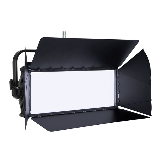
DIMENSIONAL DRAWINGS JUNIOR PIN INSTALLED BARNDOOR INSTALLED... -
Page 51: Optional Accessories | Fcc Statement
OPTIONAL ACCESSORIES ORDER CODE ITEM KLP103 KL Panel XL KLP972 KL Panel Intensifier Lens FCC STATEMENT This device complies with Part 15 of the FCC Rules. Operation is subject to the following two condi- tions: (1) this device may not cause harmful interference, and (2) this device must accept any inter- ference received, including interference that may cause undesired operation.