
Related Manuals for Elation KL Panel KLP001


Summary of Contents for Elation KL Panel KLP001
- Page 1 Black version C/50 M/50 Y/50 K/100 White version C/0 M/0 Y/0 K/0 KL Panel User Manual...
- Page 2 +31 45 546 85 66 | +31 45 546 85 96 fax | www.elationlighting.eu | info@elationlighting.eu Elation Professional Mexico | AV Santa Ana 30 | Parque Industrial Lerma, Lerma, Mexico 52000 +52 (728) 282-7070 D O C U M E N T V E R S I O N...
-
Page 3: Table Of Contents
C O N T E N T S General Information Limited Warranty (USA Only) Safety Guidelines Maintenance Guidelines Fixture Overview Installation Instructions System Menu Manual Mode DMX Channel Functions & Values Dimmer Modes CCT Table Virtual Colors Table Specifications Dimensional Drawings FCC Statement... -
Page 4: General Information
Junior Pin (1 in. – 28mm) with Mounting Hardware Locking Power Cable CUSTOMER SUPPORT Contact ELATION Service for any product related service and support needs. Also visit forums.elationlighting.com with questions, comments or suggestions. ELATION SERVICE USA - Monday - Friday 8:00am to 4:30pm PST 323-582-3322 | Fax 323-832-9142 | support@elationlighting.com... -
Page 5: Limited Warranty (Usa Only)
It is the owner’s responsibility to establish the date and place of purchase by acceptable evidence, at the time service is sought. B. For warranty service, send the product only to the Elation Professional factory. All shipping charges must be pre-paid. If the requested repairs or service (including parts replacement) are within the terms of this warranty, Elation Professional will pay return shipping charges only to a designated point within the United States. -
Page 6: Safety Guidelines
This fixture is a sophisticated piece of electronic equipment. To guarantee smooth operation, it is important to follow all instructions and guidelines in this manual. Elation Professional is not responsible for injury and/or damages resulting from the misuse of this fixture due to the disregard of the information printed in this manual. - Page 7 S A F E T Y G U I D E L I N E S DO NOT TOUCH the fixture housing during operation. Turn OFF the power and allow approximately 15 minutes for the fixture to cool down before serving. DO NOT shake fixture, and avoid brute force when installing and/or operating fixture.
-
Page 8: Maintenance Guidelines
Regular inspections are recommended to ensure proper function and extended life. There are no user serviceable parts inside this fixture, please refer all other service issues to an authorized Elation service technician. Should you need any spare parts, please order genuine parts from your local Elation dealer. -
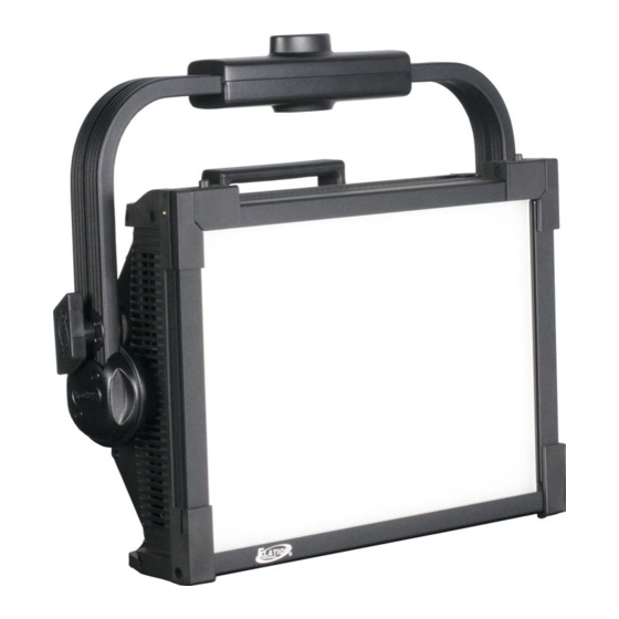
Page 9: Fixture Overview
F I X T U R E O V E R V I E W 1. Removable Diffuser 2. Yoke Adjustment Knob 3. Mounting Yoke 4. Clamp Mounting Point 5. Diffuser Frame Lock Tab 6. Carry Handle 7. Network In Connection 8. -
Page 10: Installation Instructions
I N S T A L L A T I O N I N S T R U C T I O N S FLAMMABLE MATERIAL WARNING Keep fixture minimum 5.0 feet (1.5m) away from flammable materials and/or pyrotechnics. ELECTRICAL CONNECTIONS A qualified electrician should be used for all electrical connections and/or installations. - Page 11 I N S T A L L A T I O N I N S T R U C T I O N S CLAMP INSTALLATION This fixture includes an adjustable mounting yoke with an integrated clamp mounting point, as well as two (2) safety cable rigging points attached to the body of the fixture (see the illustration below).
- Page 12 I N S T A L L A T I O N I N S T R U C T I O N S BARN DOOR 1. Unlock both diffuser frame lock tabs using the latches located on each tab. Flip the top edge of the frame upward.
- Page 13 I N S T A L L A T I O N I N S T R U C T I O N S BARN DOOR 3. Flip the top edge of the frame downwards, and engage the lock tabs. 4.
- Page 14 I N S T A L L A T I O N I N S T R U C T I O N S JUNIOR PIN 1. Loosen the yoke adjustment knobs, and adjust the mounting yoke to a position that allows access to both the top and bottom sides of the yoke.
- Page 15 I N S T A L L A T I O N I N S T R U C T I O N S JUNIOR PIN 3. Thread the junior pin bolt in through the under side of the mounting yoke, making sure that the bolt engages the threaded hole in the junior pin.
-
Page 16: System Menu
S Y S T E M M E N U The fixture includes an easy to navigate system menu. The control panel (see image below) located on the back of the fixture provides access to the main system menu, where all necessary system adjustments are made. - Page 17 S Y S T E M M E N U Elation KL Panel System Menu Supports Software Versions: 1.01 Disabled Int CCT Grn See Manual Mode MANUAL MODE section for details Int Color Sat Manual Control DMX Address 001 – 512...
- Page 18 LED Power Limit 100% Screen Saver Delay 3 – 10s Note: To unlock screen, press and hold MODE Display Screen Lock button for 3 seconds. Rotate Display 180° PERSONALITY Switch On / Off (continued from prev Univers 000 – 255 page) Network Subnet...
-
Page 19: Manual Mode
M A N U A L M O D E ENCODER KNOB DESIGNATIONS INT CCT GRN (INTENSITY, COLOR TEMPERATURE, GREEN SHIFT) Elation KL Panel Manual Mode – Intensity, Color Temperature, Green Shift Supports Software Versions: 1.01 Encoder Parameter Display Resolution/ Steps... - Page 20 M A N U A L M O D E INT COL SAT (INTENSITY, COLOR, SATURATION) Elation KL Panel Manual Mode – Intensity, Color, Saturation Supports Software Versions: 1.01 Encoder Parameter Display Resolution/ Steps Default Knob Intensity Intensity 0-100% Color White, Virtual Color 1, 2, 3, 4…...
-
Page 21: Dmx Channel Functions & Values
CHANNEL VALUE FUNCTION DEFAULT SNAP 000 – 255 Dimmer Intensity, 0 to 100% 4-CH DIMMER COLOR MODE Elation KL Panel DMX Channels / Functions (4 DMX Channels, Dimmer Color Mode) Supports Software Versions: 1.01 CHANNEL VALUE FUNCTION DEFAULT SNAP 000 – 255 Dimmer Intensity, 0 to 100% 000 –... - Page 22 7-CH DIMMER COLOR FX MODE Elation KL Panel DMX Channels / Functions (7 DMX Channels, Dimmer Color FX Mode) Supports Software Versions: 1.01 CHANNEL VALUE FUNCTION DEFAULT SNAP 000 – 255 Dimmer Intensity, 0 to 100% 000 – 255 Dimmer Fine 000 –...
- Page 23 12-CH RGBWLC 16-BIT MODE Elation KL Panel DMX Channels / Functions (12 DMX Channels, RGBWLC 16-bit Mode) Supports Software Versions: 1.01 CHANNEL VALUE FUNCTION DEFAULT SNAP 000 – 255 Red, 0 to 100% 000 – 255 Red Fine, 0 to 100% 000 –...
- Page 24 CHANNEL VALUE FUNCTION DEFAULT SNAP Color Wheel Open 001 – 179 Virtual Swatch Book (see Virtual Colors Table) Color Scroll 180 – 201 Clockwise, Fast to Slow 202 – 207 Stop 208 – 229 Counter-clockwise, Slow to Fast 230 – 234 Open Random Color Scroll 235 –...
- Page 25 CHANNEL VALUE FUNCTION DEFAULT SNAP Refresh Rate 900 Hz 910 Hz 920 Hz 930 Hz 940 Hz 950 Hz 960 Hz 970 Hz 980 Hz 990 Hz 1000 Hz 1010 Hz 1020 Hz 1030 Hz 1040 Hz 1050 Hz 1060 Hz 1070 Hz 1080 Hz 1090 Hz...
- Page 26 CHANNEL VALUE FUNCTION DEFAULT SNAP Refresh Rate (continued from prev page) 1400 Hz 1410 Hz 1420 Hz 1430 Hz 1440 Hz 1450 Hz 1460 Hz 1470 Hz 1480 Hz 1490 Hz 1500 Hz 2500 Hz 4000 Hz 5000 Hz 6000 Hz (continued 10000 Hz Snap...
- Page 27 23-CH EXTENDED MODE Elation KL Panel DMX Channels / Functions (23 DMX Channels, Extended Mode) Supports Software Versions: 1.01 CHANNEL VALUE FUNCTION DEFAULT SNAP Strobe 000 – 031 Shutter Closed 032 – 063 No Function (Shutter Open) 064 – 095 Strobe Effect, Slow to Fast 096 –...
- Page 28 CHANNEL VALUE FUNCTION DEFAULT SNAP Dim Modes 000 – 020 Standard 021 – 040 Stage 041 – 060 061 – 080 Architectural 081 – 100 Theatre 101 – 120 Stage 2 Dimmer Display Time 0.1 s 0.2 s 0.3 s 0.4 s 0.5 s 0.6 s...
- Page 29 CHANNEL VALUE FUNCTION DEFAULT SNAP Refresh Rate (continued from prev page) 1020 Hz 1030 Hz 1040 Hz 1050 Hz 1060 Hz 1070 Hz 1080 Hz 1090 Hz 1100 Hz 1110 Hz 1120 Hz 1130 Hz 1140 Hz 1150 Hz 1160 Hz 1170 Hz 1180 Hz 1190 Hz...
- Page 30 121 – 140 Random Pixel Order 141 – 255 Random Steps *Internal FX currently are not implemented. 4-CH HSI MODE Elation KL Panel DMX Channels / Functions (4 DMX Channels, HSI Mode) Supports Software Versions: 1.01 CHANNEL VALUE FUNCTION DEFAULT SNAP 000 –...
- Page 31 12-CH HSI EXTENDED MODE Elation KL Panel DMX Channels / Functions (12 DMX Channels, HSI Extended Mode) Supports Software Versions: 1.01 CHANNEL VALUE FUNCTION DEFAULT SNAP Strobe 000 – 031 Shutter Closed 032 – 063 No Function (Shutter Open) 064 – 095 Strobe Effect, Slow to Fast 096 –...
- Page 32 CHANNEL VALUE FUNCTION DEFAULT SNAP Dimmer Delay Time (continued from prev page) 0.8 s 0.9 s 1.0 s 1.5 s 2.0 s 3.0 s (continued 4.0 s Snap from prev 5.0 s page) 6.0 s 7.0 s 8.0 s 9.0 s 10.0 s 142 –...
- Page 33 CHANNEL VALUE FUNCTION DEFAULT SNAP Dimmer Delay Time (continued from prev page) 1210 Hz 1220 Hz 1230 Hz 1240 Hz 1250 Hz 1260 Hz 1270 Hz 1280 Hz 1290 Hz 1300 Hz 1310 Hz 1320 Hz 1330 Hz 1340 Hz 1350 Hz 1360 Hz 1370 Hz...
- Page 34 CHANNEL VALUE FUNCTION DEFAULT SNAP Internal Program 6 (Scene 41 – 48) (continued Internal Program 7 (Scene 49 – 56) Snap from prev 248 – 255 Idle page) 000 – 255 FX Selection* Snap 000 – 255 FX Adjustment Fade FX Offset Idle Fixture Offset, 10°...
-
Page 35: Dimmer Modes
D I M M E R M O D E S Select desired DIMMER MODE (Standard, Stage, TV, Architectural, Theatre, Stage2). 100% 100% 100% 100% DMX % DMX % DMX % DMX % LINEAR SQUARE INVERSE SQUARE S-CURVE... -
Page 36: Cct Table
C C T T A B L E Elation KL Panel Color Temperature Table VALUE COLOR TEMP VALUE COLOR TEMP 2000 K 6100 K 2100 K 6200 K 2200 K 6300 K 2300 K 6400 K 2400 K 6500 K... -
Page 37: Virtual Colors Table
V I R T U A L C O L O R S T A B L E Elation KL Panel Virtual Colors Table VALUE FILTER # NAME VALUE FILTER # NAME Pale Yellow Magenta Straw Dark Magenta Gold Tint... -
Page 38: Specifications
S P E C I F I C A T I O N S SOURCE 6-in-1 (Red, Green, Blue, White, Lime, Cyan) LED Array 50,000 Hour Average LED Life* *Test lab conditions. May vary depending on several factors including but not limited to: Environmental Conditions, Power/Voltage, Usage Patterns (On-Off Cycling), Control, and Dimming. -
Page 39: Dimensional Drawings
D I M E N S I O N A L D R A W I N G S FIXTURE ONLY Drawings not to scale. - Page 40 D I M E N S I O N A L D R A W I N G S BARN DOOR AND JUNIOR PIN INSTALLED Drawings not to scale.
-
Page 41: Fcc Statement
F C C S T A T E M E N T This device complies with Part 15 of the FCC Rules. Operation is subject to the following two conditions: (1) this device may not cause harmful interference, and (2) this device must accept any interference received, including interference that may cause undesired operation. - Page 42 SKU#: KLP001 EU#: 1237000224 UPC#: 810008261569...