
Related Manuals for CAME GGT40AGS


Summary of Contents for CAME GGT40AGS
- Page 1 Automatic road barriers FA01383-EN GGT40AGS GGT40RGS GGT40RX4 GGT40AX4 GGT40AX6 GGT40ACS English INSTALLATION MANUAL...
- Page 2 DEVICE MANUAL RELEASE Releasing the device may be dangerous for the user, if the boom fastening has been damaged or if the boom is no longer intact, as the result of an accident or installation error. In these cases, the tensioned springs no longer guarantee that the boom is balanced. The boom may suddenly rotate when being released. Manual release may cause the operator to move in an uncontrolled manner due to a mechanical fault or an imbalance.
- Page 3 GENERAL PRECAUTIONS FOR INSTALLERS Important safety instructions. Please follow all of these instructions. Improper installation may cause serious bodily harm. Before continuing, please also read the general precautions for users. Only use this product for its intended purpose. Any other use is hazardous. • The manufacturer cannot be held liable for any damage caused by improper, unreasonable or erroneous use.
-
Page 4: Dismantling And Disposal
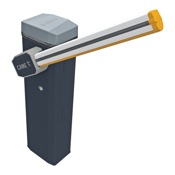
DISMANTLING AND DISPOSAL CAME S.p.A. employs an Environmental Management System at its premises. This system is certified and compliant with the UNI EN ISO 14001 standard to ensure that the environment is respected and safeguarded. Please continue safeguarding the environment. At CAME we consider it one of the fundamentals of our operating and market strategies. - Page 5 Description 803BB-0160 GGT40AGS - Automatic barrier with gearmotor 24 V DC with encoder; painted galvanised steel cabinet; accessories available. Balance spring included. 803BB-0200 GGT40RGS - Automatic barrier with irreversible gearmotor 24 V DC with encoder; painted galvanised steel cabinet; accessories available. Balance spring included.
-
Page 6: Description Of Parts
Description of parts Barrier Cover Lever arm Gear motor with encoder Boom anchoring plate Auxiliary Intermediate plate Line fuse Fastening flange Power supply terminal board Anti-shearing cover Anchoring plate DIR/DXR photocell holes Anchoring bracket Lock for release Boom profile end cap Cabinet Spring anchoring pin Inspection hatch... -
Page 7: Control Board
Terminal board for connecting the transponder selector switch Motor fuse Terminal board associated with the RSE_1 connector for paired, alternate or Connector for CAME KEY CRP connection Memory Roll card connector Terminal board associated with the RSE_2 connector for CRP connection, IO... - Page 8 Size max. 4000 Cable types and minimum thicknesses Cable length (m) up to 20 from 20 to 30 Power supply 230 V AC 3G x 1.5 mm² 3G x 2.5 mm² Power supply 120 V AC 3G x 1.5 mm² 3G x 2.5 mm²...
-
Page 9: Installation
INSTALLATION The following illustrations are examples only. The space available for fitting the operator and accessories varies depending on the area where it is installed. It is up to the installer to find the most suitable solution. In case of manual handling, have one person for every 20 kg that needs hoisting; for non-manual handling, use proper hoisting equipment in safe conditions. When the operator is being fixed in place, it may be unstable and overturn. - Page 10 Fill the hole with soil around the concrete block. Remove the nuts from the screws. Thread the electrical cables into the tubes so that they protrude by about 1500 mm. Preparing the barrier With the inspection hatch open, the operator does not work. Fastening the barrier...
-
Page 11: Boom Installation
Changing the boom opening direction Boom installation Insert the reinforcement inside the boom. Fix the flange and the intermediate plate to the boom. First install the LED strip (where applicable), ONLY THEN fix the flange and the intermediate plate. - Page 12 Fix the boom to the anchoring plate. Cut the slot-cover profiles to the same size as the boom slot minus 10 millimetres. Insert the slot-cover profiles into the grooves on both sides of the boom. Insert the anti-impact rubber profile into the groove. Cut off the excess part of the profile.
- Page 13 Choosing the hole for fixing the balance spring Passage width clearance (m) 2,25 < 2,75 2,75 < 3,25 3,25 < 3,50 3,50 < 3,75 3,75 < 4,00 Boom with LED strip Boom with LED strip and single skirt Boom with LED strip and full-height skirt Boom with LED strip and swing rest Boom with LED strip, single skirt and swing rest Boom with LED strip, full-height skirt and swing rest...
- Page 14 Assembling the balance spring Release the gearmotor. Tighten the eyelet tie rod to the lower part of the spring. Position the boom vertically. Screw the spring to the anchoring pin. Lock the gearmotor Hook the eyelet rod onto the anchoring bracket. 4 5 6 Assemble the anchoring pin and fix it on the lever arm.
- Page 15 Balancing the boom Release the gearmotor. Lock the gearmotor Manually turn the spring to increase or reduce the traction. The boom Check the proper working state of the spring. When the boom is vertical, should stabilise at 45°. the spring is not taut. When the boom is horizontal, the spring is taut. Fasten the locknut.
- Page 16 Determining the travel end points with mechanical limit switches Check that the boom is parallel to the road surface when it is in the closed position and at about 89° when it is in the open position. Correct the boom’s horizontal position Release the gearmotor.
- Page 17 Correct the boom’s vertical position Release the gearmotor. Open the inspection hatch. Turn the mechanical stop until you reach the desired boom position. Fasten the mechanical stop with a locknut. Lock the gearmotor ~1° ~89°...
-
Page 18: Electrical Connections
ELECTRICAL CONNECTIONS Passing the electrical cables The electrical cables must not touch any parts that may overheat during use (such as the motor and transformer). Make sure that the moving mechanical parts are suitably far away from the wiring. Power supply Make sure the mains power supply is disconnected during all installation procedures. -
Page 19: Cable Type
24 DC Devices with BUS CXN system The CXN CAME system is a two-wire non-polarised communication BUS which allows you to connect up all compatible CAME devices. Connection to the BUS can be in a chain, star or mixed formation. - Page 20 Command and control devices STOP button (NC contact) This stops the boom and excludes automatic closing. Use a control device to resume movement. If the contact is not used, it must be deactivated during programming. Control device (NO contact) OPEN ONLY function When the [HOLD-TO-RUN] function is active, the control device must be connected during OPENING.
-
Page 21: Signalling Devices
Signalling devices Additional light It increases the light in the manoeuvring area. Additional flashing beacon It flashes when the operator opens and closes. Operator status warning light It notifies the user of the operator status. RGB LED strip and/or RGB crown If the red LEDs are flashing, the operator is moving. - Page 22 DIR / DELTA-S photocells DIR / DELTA-S photocells Standard connection Connection with safety test Multiple photocell pairs can be connected. Multiple photocell pairs can be connected. See function [F5] Safety devices test. 10 11 E1 TS 1 3 3P 4 2 CX CY CZ 10 11 E1 TS 1 3 3P 4...
-
Page 23: Getting Started
PROGRAMMING Programming button functions ESC button The ESC button is used to perform the operations described below. Exit the menu Delete the changes Go back to the previous screen < > buttons The <> buttons are used to perform the operations described below. Navigate the menu Increase or decrease values ENTER button... - Page 24 CX input Associate a function with the CX input. CX input OFF (Default) C1 = Reopen while closing (photocells) C4 = Obstacle standby (photocells) C5 = Immediate closure at the travel end during opening C7 = Reopen while closing (sensitive edges) C9 = Immediate closure at the travel end during opening with obstacle standby during closure C10 = Immediate closure during opening with obstacle standby during closure (NO...
- Page 25 Safety devices test Check that the photocells connected to the inputs are operating correctly, after each opening and closing command. Safety devices test OFF (Default) 1 = CX 2 = CY 3 = CX+CY 4 = CZ 5 = CX+CZ 6 = CY+CZ 7 = CX+CY+CZ Hold-to-run...
-
Page 26: Automatic Closure
Light E1 Choose the type of device connected to the output. Light E1 0 =Flashing beacon (Default) 1 = Cycle light This parameter does not appear if there [Automatic Close] function is deactivated. 2 = Courtesy light. The lighting device remains on for the time set for the [Courtesy time] function. Automatic closure Set the time before automatic closure is activated, once the opening travel end point has been reached. - Page 27 Configure the function to be performed by the card inserted in the RSE_1 and RSE_2 connectors. If an RSE card – configured for paired connections – is plugged into the RSE_1 connector, use the RSE_2 connector for remote connection (CRP). In this case, a CAME KEY cannot be connected. 1 = Paired...
- Page 28 Pre-flashing Choose the type of manoeuvre that activates the flashing beacon in advance. Set how much earlier the flashing beacon is activated under the function [Pre-flashing time]. Pre-flashing 0 = when opening and closing (Default) 1 = only when closing 2 = only when opening RSE speed Set the communication speed of the remote connection system on the RSE_1 and RSE_2 ports.
- Page 29 New user Register up to a maximum of 250 users and assign a function to each one. The operation can be carried out by using a transmitter or another control device. The boards that manage the control devices (AF - R700 - R800) must be inserted into the connectors.
-
Page 30: Forgotten Password
Motor test Check the boom opens in the correct direction. If the keys do not execute the commands correctly, invert the boom opening direction. Motor test The button > makes the motor turn in clockwise direction. The button < makes the motor turn in an anticlockwise direction. Travel calibration Start the travel self-learning. -
Page 31: Import/Export Data
Photocell BUS <n> Associate a function with the photocell BUS <n> input. <n> is between 1 and 8 and corresponds to the address set on the photocell dip-switch B1-B8 Photocell BUS <n> OFF (Default) C1 = Reopen while closing (photocells) C4 = Obstacle standby (photocells) C5 = Immediate closure at the travel end during opening C9 = Immediate closure at the travel end during opening with obstacle standby during... -
Page 32: Final Operations
FINAL OPERATIONS... -
Page 33: Electrical Connections
PAIRED OPERATION Two connected operators are controlled with one command. Electrical connections Connect the two electronic boards with a UTP CAT 5 cable. Fit an RSE card on both control boards, using the RSE_1 connector. Connect up the electrics for the devices and accessories. For information on connecting the electrics for the devices and accessories, please see the “ELECTRICAL CONNECTIONS”... -
Page 34: Alternate Operation
ALTERNATE OPERATION The first barrier opens, the vehicle passes, the first barrier closes, the second barrier opens, the vehicle passes and the second barrier closes. Electrical connections Connect the two electronic boards with a UTP CAT 5 cable. Fit an RSE card on both control boards, using the RSE_1 connector. Connect up the electrics for the devices and accessories. - Page 35 ONLY OPEN command (2-3) on barrier B OPEN-CLOSE command (2-7) on barrier A or B for emergency opening...
- Page 36 MCBF Models Standard boom L = 4.2 m 3.000.000 Skirt -20% Mobile foot -20% Articulated joint -20% Full-height skirt -30% The MCBF value relates to the barrier only and does not refer to any applicable accessories. The GARD GT barrier has been designed to perform up to 3 million cycles. Thanks to its 24V DC motor, it is extremely reliable and requires very little maintenance.
-
Page 37: Error Messages
ERROR MESSAGES Calibration error Encoder failure error Service test failure error Operating time error Open release-hatch error Obstacle detected during closing Obstacle detected during opening The maximum number of obstacles detected consecutively has been exceeded Serial communication error Incompatible transmitter error Open SLAVE-motor hatch error... - Page 40 CAME S.p.A. Via Martiri della Libertà, 15 31030 Dosson di Casier Treviso - Italy Tel. (+39) 0422 4940 Fax (+39) 0422 4941...