Table of Contents
Advertisement
Quick Links
Advertisement
Table of Contents

Related Manuals for Bosch Rexroth MKE035B-144


Summary of Contents for Bosch Rexroth MKE035B-144
- Page 1 Industrial Electric Drives Linear Motion and Service Mobile Hydraulics and Controls Assembly Technologies Pneumatics Automation Hydraulics Rexroth IndraControl VCP 20 Rexroth MKE synchronous motors R911274804 Edition 01 for potentially hazardous areas Project Planning Manual...
- Page 2 MKE Digital AC Motors for potentially-explosive areas Title Project Planning Manual type of documentation DOK-MOTOR*-MKE*******-PRJ1-EN-E1,44 Document code • Drawing number: 209-0078-4301-00 Internal file reference Reference This electonic document is based on the hardcopy document with docu- ment desig.: DOK-MOTOR*-MKE*******-PRJ1-EN-P This document assists in The purpose of the documentation: •...
-
Page 3: Table Of Contents
Contents 1 Introduction to MKE digital AC motors 1.1 General features ..........................1-1 1.2 Versions ............................... 1-3 1.3 Motor feedback ............................ 1-3 2 Mechanical integration into the machine 2.1 Using the drive in potentially explosive areas..................2-1 2.2 Conditions of Use..........................2-2 Maximum installation elevation and ambient temperature............ - Page 4 5.2 Speed/torque characteristics ....................... 5-2 5.3 Determining maximum shaft load ......................5-3 5.4 Dimensions ............................5-4 5.5 Available versions and type codes....................... 5-5 6 MKE 096 6.1 Technical data............................6-1 6.2 Speed/torque characteristics ....................... 6-2 6.3 Determining maximum shaft load ......................6-3 6.4 Dimensions ............................
- Page 5 12.3 Contacting Customer Service ......................12-2 13 Index 13-1 DOK-MOTOR*-MKE*******-PRJ1-EN-E1,44 • 06.97 Introduction to MKE digital AC motors...
- Page 6 DOK-MOTOR*-MKE*******-PRJ1-EN-E1,44 • 06.97 Contents...
-
Page 7: Introduction To Mke Digital Ac Motors
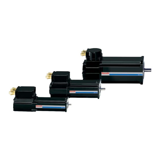
Introduction to MKE digital AC motors General features In conjunction with digital intelligent INDRAMAT drive controllers, MKE Applications digital AC motors create cost-effective drive systems with a broad range of functionalities for use in potentially explosive areas. Motors with the following continuous standstill torques and nominal Overview of performance speeds are available: Fig. - Page 8 Advantages The salient advantages of MKE motors are as follows: • motors designed with „pressure-resistant housing“ as per EN 50014 ff • extreme operating reliability • maintenance-free operation (due to the brushless design and use of lifetime lubricated bearings) • implementation even under adverse environmental conditions (due to the completely sealed motor design with protection category IP 65) •...
-
Page 9: Versions
MKE motors are intended for use with the following drive controllers: Drive controller family DIAX04 ECODRIVE Drive controller Fig. 1-2: Drive controllers for MKE motors Versions MKE motors are available in different versions: They are available with Motor feedback • relative rotor position evaluation (standard) or •... - Page 10 Feedback electronics are equipped with data memory in which motor type Feedback data storage designations, control loops and motor parameters are stored. The digital intelligent drive controllers from INDRAMAT can read this data thus guaranteeing • an easy and quick startup •...
-
Page 11: Mechanical Integration Into The Machine
Mechanical integration into the machine Using the drive in potentially explosive areas The figure below illustrates how to mount the drive in potentially explosive areas. The following components must meet the demands made for ex- plosion protection: • motor with mountable components •... -
Page 12: Conditions Of Use
Conditions of Use Maximum installation elevation and ambient temperature The power data of the motor apply to Nominal data • an ambient temperature range of 0º to +40º C • and an installation elevation of 0 to 1000 meters above sea level. If the motor is to be used above this range, then the "load factors"... -
Page 13: Maximum Vibration And Shock Requirements
The design of MKE motors meets the protection category requirements Protection category as described in DIN VDE 0470, section 1, edition 11/1992: Area of the motor Protection category Motor housing, drive shaft, power & feedback connect ions (only with proper mounting) IP 65 Fig. -
Page 14: Primary Coat And Housing Finish
According to IEC 721-3-3, edition 1987 or EN 60721-3-3, edition 06/1994, MKE motors may be operated in a stationary and weather protected man- ner under the following conditions: • longitundinal axis of the motor as per class 3M1 • lateral axis of the motor as per class 3M4 ⇒... -
Page 15: Type Of Construction And Mounting Orientation
Type of construction and mounting orientation Type of construction: B05 for flange mounting Orientation: Per DIN IEC 34-7, edition 12/1992, the following orientations are permit- ted: • IM B5 (horizontal) • IM V1 (vertical, drive shaft downward) • IM V3 (vertical, drive shaft upward) Seeping of liquids! Motors mounted as per IM V3 are susceptible to seeping liquids that collect over extended periods at the shaft and... - Page 16 Motor damage and forfeiture of guarantee! Excessive shaft loads can damage the motor and shor- ten bearing life span considerably. The guarantee is also forfeited. WARNING ⇒ Please therefore note the following instructions! Maximum permissible radial force F depends on shaft/force load. Maximum permissible radial_max It is determined in terms of distance x of the point of application of force...
- Page 17 It is proportional to the permissible radial force F Permissible axial force F axial radial The factor of proportionality can be found in sections 4 to 6 in section "Determining maximum shaft load". ⇒ Using the given formula, determine maximum permissible axial force for your application.
-
Page 18: Holding Brake
Holding brake Optional. Holds the servo axis when no power is being supplied to the machine. The holding brake works with the "electrically-released" principle. At zero current, a magnetic force acts on the brake armature disc. This means that the brake is locked and holding off the axis. With the application of 24 V DC, the electrical field cancels the permanent magnetic field and the brake opens. -
Page 19: Connection Variants And Cable Output Directions
Connection variants and cable output directions A cable connection box is generally used for the MKE motor power and feedback connections. The desired cable output direction can be set at the time of mounting by turning the cable connection box. Fig. -
Page 20: Speed And Torque
Speed and Torque The rotational speed/torque characteristics depict • the torque limit data • the rotational speed limit data and • operating characteristics A diagram for each motor can be found in sections 4 to 6 under the topic „Speed/torque characteristics“. ⇒... - Page 21 As of "peak-torque" speed, maximum achievable, usable speed depends Characteristics (1) to (5) on the torque required. Since maximum motor speed is fixed by the DC bus voltage used, separate characteristics result for the individual drive controllers in terms of their supply voltage or the power supply unit used: (1) HDS or HDD attached to supply units HVR (2) HDS or HDD with power supply unit HVE with a mains connection of 3 x AC 480 V or- DKC..-...-7 with 3 x AC 480 V...
- Page 22 2-12 DOK-MOTOR*-MKE*******-PRJ1-EN-E1,44 • 06.97 Mechanical integration into the machine...
-
Page 23: Electrical Connections
Electrical connections Overview of connections The electrical connections of INDRAMAT drives are standardized. On MKE AC motors there are • a power connection - includes connections for temperature sensors and holding brake - and • a feedback connection. Depending on the motor, both connections are conducted into the cable connection box with the use of EExd-cable leadthroughs, where they are mounted with a plug contact (see section 11.4 „Connecting the motor“, page11-2). -
Page 24: Connections For Motors With Terminal Boxes
Connections for motors with terminal boxes Terminal diagram Note: Only direct connections between motor and drive controller are depicted. The terminal diagrams, however, also apply to all other types, e.g., with intermediate connector, as the allocation of the connections of motor and drive controller never change. Fig. -
Page 25: Thermal Cutout Connection
Thermal cutout connection The use of an integrated motor temperature evaluation circuit in INDRAMAT drive controllers is urgently recommended to evaluate motor temperature in MKE motors used in areas where explosions represent a risk. The PTC resistor connection for motor temperature evaluation is illustra- ted in the terminal diagram of the relevant drive controller. - Page 26 Fig. 3-3: Different types of connecting cables ⇒ Please find the type that suits your motor/controller combination in the table below. ⇒ If type designations are specified for two cables or a cable and a flan- ged socket, then order both. DOK-MOTOR*-MKE*******-PRJ1-EN-E1,44 •...
-
Page 27: Feedback Cable
Connecting drive controller DIAX04 or ECODRIVE Motor Direct connection Connected via pluggable isolating point type motor to motor to MKE... HDD/ Terminal Flanged HDD/ Terminal 100A 75/100A strip socket 100A 75/10 strip 035B- IKG- in prep. in prep. in prep. in prep. -
Page 28: Technical Data Of The Power And Feedback Cables
⇒ Locate the cable which suits your motor/controller combination in the table below. Motor type Direct connection Connected via of motor to drive pluggable isolating controller point motor to drive controller all motor types with IKS0203 in prep. terminal box Fig. -
Page 29: Minimum Temperature Resistance Of The Connecting Leads
Minimum temperature resistance of the connecting leads To use MKE motors in potentially explosive areas, cables with a minimum temperature resistance of 80°C (176° F) must be used. The cables listed in the INDRAMAT cable selection lists meet these requirements. Individual parts Note: INDRAMAT cables can be put together by the customer. - Page 30 DOK-MOTOR*-MKE*******-PRJ1-EN-E1,44 • 06.97 Electrical connections...
-
Page 31: Mke 035
MKE 035 Technical data Designation Symbol Unit Data Motor type MKE035B-144 to run with drive controller family DIAX04, ECODRIVE drive controllers HDS, HDD, DKC nominal motor speed 9000 continuous torque at standstill 0.9 (0.8) continuous current at standstill 5.1 (4.5) theoretical maximum torque peak current 23.0... -
Page 32: Speed/Torque Characteristics
Designation Symbol Unit Holding brake data Holding torque Nominal voltage DC 24 ±10% Nennstrom Moment of inertia kgm² 0.08 x 10 Release delay Clamping delay Mass 0.25 Fig. 4-2: Technical data - holding brake - MKE035 (Optional) Speed/torque characteristics For details see section 2.7, Speed and Torque, page 2-10. Fig. -
Page 33: Determining Maximum Shaft Load
Determining maximum shaft load For details see section 2.4, section Shaft loads , page 2-5. Permissible maximum radial force F and permissible radial_max radial force F radial Fig. 4-4: MKE035: permissible maximum radial force F and permissible radial_max radial force F radial Permissible axial force F ⋅... -
Page 34: Dimensions
Dimensions Fig. 4-5: Dimensional data MKE035 DOK-MOTOR*-MKE*******-PRJ1-EN-E1,44 • 06.97 MKE 035... -
Page 35: Available Versions And Type Codes
Available versions and type codes Fig. 4-6: Type codes MKE035 DOK-MOTOR*-MKE*******-PRJ1-EN-E1,44 • 06.97 MKE 035... - Page 36 DOK-MOTOR*-MKE*******-PRJ1-EN-E1,44 • 06.97 MKE 035...
-
Page 37: Mke 045
MKE 045 Technical data Designation Symbol Unit Data Motor type MKE045B-144 to run with drive controller family DIAX04, ECODRIVE drive controllers HDS, HDD, DKC nominal motor speed 6000 continuous torque at standstill continuous current at standstill theoretical maximum torque 11.3 peak current 34.0 rotor inertia... -
Page 38: Speed/Torque Characteristics
Designation Symbol Unit Holding brake data Holding torque Nominal voltage DC 24 ±10% Nominal current 0.35 Moment of inertia kgm² 0.16 x 10 Release delay Clamping delay mass 0.25 Fig. 5-2: Technical data - holding brake - MKE045 (Optional) Speed/torque characteristics For details see section 2.7, Speed and Torque, page 2-10. -
Page 39: Determining Maximum Shaft Load
Determining maximum shaft load For details see section 2.4, Shaft loads , page 2-5. Permissible maximum radial force F and permissible radial_max radial force F radial Fig. 5-4: MKE045: Permissible maximum radial force F and permissible radial_max radial force F radial Permissible axial force F axial... -
Page 40: Dimensions
Dimensions Fig. 5-6: Dimensional data - MKE045 DOK-MOTOR*-MKE*******-PRJ1-EN-E1,44 • 06.97 MKE 045... -
Page 41: Available Versions And Type Codes
Available versions and type codes Fig. 5-7: Type codes MKE045 DOK-MOTOR*-MKE*******-PRJ1-EN-E1,44 • 06.97 MKE 045... - Page 42 DOK-MOTOR*-MKE*******-PRJ1-EN-E1,44 • 06.97 MKE 045...
- Page 43 MKE 096 Technical data Designation Symbol Unit Data Motor type MKE096B-047 to run with drive controller fa- DIAX04, ECODRIVE mily drive controllers HDS, HDD, DKC nominal motor speed 3200 continuous torque at standstill 12.0 continuous current at standstill 13.2 theoretical maximum torque 43.5 peak current 59.4...
- Page 44 Designation Symbol Unit Holding brake data Holding torque 11.0 Nominal voltage DC 24 ±10% Nominal current Moment of inertia kgm² 1.1 x 10 Release delay Clamping delay mass 0.65 Fig. 6-2: Technical data - holding brake - MKE096 (Optional) Speed/torque characteristics For details see section 2.7, Speed and Torque, page 2-10.
- Page 45 Determining maximum shaft load For details see section 2.4, Shaft loads , page 2-5. Permissible maximum radial force F and permissible radial_max radial force F radial Fig. 6-4: MKE096: Permissible maximum radial force F and permissible radial_max radial force F radial Permissible axial force F ⋅...
- Page 46 Dimensions Fig. 6-6: Dimensional data MKE096 DOK-MOTOR*-MKE*******-PRJ1-EN-E1,44 • 06.97 MKE 096...
- Page 47 Available versions and type codes Fig. 6-7: Type codes MKE096 DOK-MOTOR*-MKE*******-PRJ1-EN-E1,44 • 06.97 MKE 096...
- Page 48 DOK-MOTOR*-MKE*******-PRJ1-EN-E1,44 • 06.97 MKE 096...
-
Page 49: Condition At Delivery
Condition at delivery General information The motor and accessories, such as cables, are loaded into cartons at delivery. Depending on number or size of these cartons, they may be loa- ded onto a pallet and then fixed into place with metal bands. For protecti- on against adverse weather, an additional carton may be placed over the palette and affixed into place with metal bands attached to the pallett. - Page 50 DOK-MOTOR*-MKE*******-PRJ1-EN-E1,44 • 06.97 Condition at delivery...
-
Page 51: Identifying The Merchandise
Identifying the merchandise Delivery slip The entire delivery is acompanied by one slip in an envelope. The merchandise is listed here by name and order number. In the event that the contents are distributed over several cartons (transport containers), such will be noted in the delivery slip or the freight papers. Barcode sticker There is a barcode sticker on each motor package will lists the following information:... -
Page 52: Type Plate
Type plate The motor is delivered with a type plate. It is attached to the motor hou- Motors sing. There is a second type plate placed over the original type plate with two-sided tape. This can be removed and placed elsewhere at a visible spot on the machine if the original type plate on the motor is somehow covered or not visible due to the contours of the machine. -
Page 53: Storage , Transport And Handling
Storage , Transport and Handling Notes on the packaging Notes on storage, transport and handling are on the packaging. Please comply with the instructions. Fig. 9-1: Notes on storage, transport and handling on the packaging Storage Motor damage and forfeiture of guarantee! Motors not properly stored could be damaged. -
Page 54: Transport And Handling
Transport and Handling Motor damage and forfeiture of guarantee! Improper transport and handling can damage the motor. The guarantee is also forfeited in this case. ⇒ Please therefore follow the instructions below. WARNING Maintain the following conditions during transport and when handling: ⇒... -
Page 55: Safety Guidelines For Electrical Drives
Safety Guidelines for electrical drives 10.1 General information • The safety instructions outlined in this document must always be complied with. Improper handling of this machinery and non- compliance with the warnings can cause property damage, injury and possibly even death. INDRAMAT assumes no responsibility for dete- rimental conditions ensuing from non-compliance with the warnings. -
Page 56: Notes On "Safely-Isolated Low Voltages
High voltage! DANGER to life or severe injury! ⇒ Comply with general setup and safety guidelines when working on high voltage facilities. DANGER ⇒ After installation, check the permanent connection of the protective conductor at all electrical components for compliance with the terminal diagram. ⇒... -
Page 57: Notes On Handling And Mounting
High electrical voltages from improper connections! DANGER to life or severe injury! ⇒ Only those devices, electrical components or lines may be connected to the signal voltages of these WARNING components if they are sufficiently and safely isolated from the connected electrical circuits as complying with set standards (as per DIN EN 50178/edition 11.94, section 5.3.2.3). - Page 58 Dangerous movements! Danger to life, severe injury or property damage! ⇒ The monitoring devices within the drive components largely exclude malfunctions. This alone should not be DANGER relied upon for personnel safety. Until the built-in monitors are activated, it should be assumed that a faulty drive motion can occur, the extent of which de- pends on the nature of the problem and the oeprating mode.
-
Page 59: Mounting And Installation
Mounting and Installation 11.1 Qualified personnel All work on the machines and drives, or work within proximity of such, must be performed by trained and qualified personnel only. The user of machine or plant must ascertain that all personnel performing •... -
Page 60: Connecting The Motor
Note: In the event the motor must be replaced, the connecting cable may remain in the lid of the terminal box. Only the motor needs to be replaced and attached to the connector on the new motor. This translates into a simple, service-friendly and quick replacement of MKE motors! 11.4 Connecting the motor Once the motor has been properly mechanically mounted, then it can be... -
Page 61: Connecting Guidelines For Mke 035 And Mke 045
Indramat’s terminal diagrams should be exclusively used for developing the wiring diagrams of the machine! ⇒ connect the motor as per the machine wiring diagrams of the manu- facturer of the machine! Use the relevant terminal diagram as depicted in Fig. 3-2: Terminal diagram of MKE motor with terminal boxal box. ⇒... - Page 62 ⇒ Cap nut (5) and washer (4) must be guided over power cable (7) or feedback cable (6). ⇒ Check cable sealing ring (3) in screwed joint (2). ⇒ Feed cable end (6) and (7) through screwed joints (2) through terminal box lid (9).
-
Page 63: Connecting Guidelines For Mke 096
Note: If the terminal box must be repeatedly mounted, or has been repeatedly remounted, then it is recommended that the fa- stening screws (8) are additionally secured with Loctite 243. Connecting guidelines for MKE 096 Terminal box or cables could be damaged! Excessive tightening torques could damage screwed jo- ints or pinch cables. - Page 64 Fig. 11-4: Feeding in power and feedback cables of MKE 096 ⇒ Pull cables back to the point where the shrink sleeve extends into the interior of the terminal box starting from the end of the screwed joint for a length of about 35 mm (up to about the middle of the terminal box lid) (see Fig.
-
Page 65: Eexd Cable Screwed Joints
EExd cable screwed joints To meet the explosion requirements, it is necessary to tighten the cable screwed joints after power and feedback cables are in place. Tightening torque: 15 Nm A tightening torque of approximately 15 Nm is achieved if the cable scre- wed joints are manually tightenend and then followed by two more turns of a suitable tool (spanner or wrench). -
Page 66: Refinishing The Holding Brake
11.5 Refinishing the holding brake Check if the holding brake is functioning properly before mounting the motor. How to check the holding brake is described below as well as procedures to follow if any refinishing of such could be necessary. Premature wear of the holding brake is possible! The holding brake wears down after appropx. -
Page 67: Service Notes
Service Notes 12.1 Changing the battery If the motor is equipped "with integrated multiturn absolute encoder", then the battery must be included in regular maintenance scheduling. The nominal lifespan of the battery equals approximately 10 years. ⇒ The following tools and aids must be handy: How to change the battery •... -
Page 68: Maintenance Work
Fig. 12-1: Changing the battery ⇒ Switch power supply to drive controllers back on. Powering machine/plant up ⇒ Run an axis test. 12.2 Maintenance work The motors should be regularly cleaned (no later than one year after as- suming operations) •... - Page 69 Fig. 12-2: MKE on DKC 12-3 DOK-MOTOR*-MKE*******-PRJ1-EN-E1,44 • 06.97 Service Notes...
- Page 70 Fig. 12-3: MKE on HDS, HDD 12-4 DOK-MOTOR*-MKE*******-PRJ1-EN-E1,44 • 06.97 Service Notes...
- Page 71 Holding brake 2-8 Index Holding brakes 1-3 Housing finish 2-4 Advantages 1-2 Identification 7-1 Ambient temperature 2-2 Individual parts 3-7 Applications 1-1 Installation elevation 2-2 Available cable lengths 3-5 Axial force Faxial 2-7 Lifting belts 9-2 Load factor 2-2 Barcode sticker 8-1 Load factors 2-2 Bearing lifespan 2-7 Maintenance work 12-2...
- Page 72 Position evaluation 1-4 Power cable 3-3 Primary coat 2-4 Protection category 2-3 Qualified personnel 11-1 Radial force Fradial 2-6 Refinishing the holding brake 11-8 Removing the battery 12-1 Resolver feedback (RSF) 1-4 Rotational speed 2-10, 4-2 Safety Guidelines Connecting the motor 11-2 General information 10-1 Protecting "safely-isolated low voltages 10-2 Protection against contact with live parts 10-1...
- Page 73 Directory of Customer Service Locations Germany Sales region central Sales region east Sales region west Sales region north INDRAMAT GmbH INDRAMAT GmbH INDRAMAT GmbH INDRAMAT GmbH D-97816 Lohr am Main D-09120 Chemnitz D-40849 Ratingen D-22085 Hamburg Bgm.-Dr.-Nebel-Str. 2 Beckerstraße 31 Hansastraße 25 Fährhausstraße 11 Telefon: 09352/40-0...
- Page 74 Outside of Europe Argentina Argentina Australia Brazil Mannesmann Rexroth S.A.I.C. Nakase Australian Industrial Machenery Mannesmann Rexroth Automação Division INDRAMAT Asesoramiento Tecnico Services Pty. Ltd. Ltda. Acassusso 48 41/7 Diaz Velez 2929 Unit 3/45 Horne ST Divisão INDRAMAT 1605 Munro (Buenos Aires) 1636 Olivos Campbellfield VIC 2061 Rua Georg Rexroth, 609...
- Page 76 Bosch Rexroth AG Electric Drives and Controls P.O. Box 13 57 97803 Lohr, Germany Bgm.-Dr.-Nebel-Str. 2 97816 Lohr, Germany Phone +49 (0)93 52-40-50 60 +49 (0)93 52-40-49 41 service.svc@boschrexroth.de www.boschrexroth.com Printed in Germany R911274804 DOK-MOTOR*-MKE*******-PRJ1-EN-P...