ADTRAN NetVanta 1224 Installation And Maintenance Practice
Quad t1 ima 24-port dslam
Hide thumbs
Also See for NetVanta 1224:
- Quick start manual (2 pages) ,
- Installation manual (2 pages) ,
- Hardware installation manual (68 pages)

Related Manuals for ADTRAN NetVanta 1224


Summary of Contents for ADTRAN NetVanta 1224
- Page 1 /E 1 ® Total Access 1224 Quad T1 IMA 24-Port DSLAM Installation and Maintenance Practice Document Number: 61179621L1-5C CLEI Number: VAMA510E_ _ January 2007...
- Page 2 In no event will ADTRAN be liable for any special, incidental, or consequential damages or for commercial losses even if ADTRAN has been advised thereof as a result of issue of this publication.
-
Page 3: Revision History
Revision History Revision Date September 2005 January 2006 January 2007 Conventions The following typographical conventions are used in this document: This font indicates a cross-reference link. indicates screen menus, fields, and parameters. This font indicates keyboard keys ( HIS FONT are shown with a plus sign ( same time This font indicates references to other documentation and is also used for emphasis. - Page 4 Radio Interference Regulation of the Canadian Department of Communications. Training ADTRAN offers training courses on our products. These courses include overviews on product features and functions while covering applications of ADTRAN product lines. ADTRAN provides a variety of training options, including customized training and courses taught at our facilities or at customer sites.
-
Page 5: Table Of Contents
Section 1 Introduction ..............1-1 General . - Page 6 Total Access 1224 Quad T1 IMA 24-Port DSLAM Installation and Maintenance Practice Section 5 User Interface..............5-1 Introduction .
- Page 7 SNMP Contact Information Menu ..........5-69 SNMP Community Names Menu .
- Page 8 ADTRAN Technical Support ........
- Page 9 Figure 1-1. Total Access 1224 ............1-1 Figure 1-2.
- Page 10 Total Access 1224 Quad T1 IMA 24-Port DSLAM Installation and Maintenance Practice Figure 5-25. ATM Port Cell Count Summary Screen ......... 5-39 Figure 5-26.
- Page 11 Figure 5-72. E1 Performance Monitoring Status Screen ........5-102 Figure 5-73.
- Page 12 Total Access 1224 Quad T1 IMA 24-Port DSLAM Installation and Maintenance Practice Figure 5-119. Contact Information Screen ..........5-161 Figure 5-120.
- Page 13 Table 1-1. Front Panel LEDs ............1-4 Table 1-2.
- Page 14 Total Access 1224 Quad T1 IMA 24-Port DSLAM Installation and Maintenance Practice Table 5-37. Restore IP Factory Defaults Menu Option ........5-59 Table 5-38.
- Page 15 Table 5-84. Status/Failure Monitoring Menu Options ........5-116 Table 5-85.
- Page 16 Total Access 1224 Quad T1 IMA 24-Port DSLAM Installation and Maintenance Practice This page is intentionally blank. 61179621L1-5C...
-
Page 17: Introduction
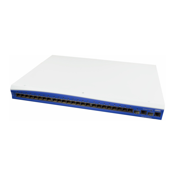
GENERAL The Total Access 1224 (see Figure (DSLAM) system that is used to further extend Asymmetrical Digital Subscriber Line (ADSL) services in the network. POTS PORTS 1-24 61179621L1-5C Section 1 Introduction 1-1) is a Digital Subscriber Line Access Multiplexer /E 1 1179621L1 ADSL+POTS PORTS 1-24 Figure 1-1. -
Page 18: Description
Total Access 1224 Quad T1 IMA 24-Port DSLAM Installation and Maintenance Practice DESCRIPTION The Total Access 1224 is a mini-DSLAM that accepts up to four T1 network feeds assigned to a single IMA group. Inverse Multiplexing over ATM (IMA) is a technology used to bond multiple (DS1) links into a single data pipe. -
Page 19: Front Panel Leds
Front Panel LEDs There are ten LEDs on the front panel of the Total Access 1224, as shown in • Two LEDs provide status information ( • Four LEDs provide the status of the four T1/E1s ( • Two LEDs provide Ethernet ( •... -
Page 20: Table 1-1. Front Panel Leds
Total Access 1224 Quad T1 IMA 24-Port DSLAM Installation and Maintenance Practice Label Status Green Yellow Yellow Green T1/E1 1–4 Green Flashing Yellow Yellow Flashing Green ETHERNET Green Flashing Yellow Green EXPANSION OUT Green Flashing Yellow Table 1-1. Front Panel LEDs Description Total Access 1224 is In Service... -
Page 21: Compliance
1. This device may not cause harmful interference. 2. This device must accept any interference received, including interference that may cause undesired operation. Changes or modifications not expressly approved by ADTRAN could void the user’s authority to operate this equipment. 61179621L1-5C Table 1-2. - Page 22 Total Access 1224 Quad T1 IMA 24-Port DSLAM Installation and Maintenance Practice This page is intentionally blank. 61179621L1-5C...
-
Page 23: Introduction
Section 2 Application Guidelines INTRODUCTION The Total Access 1224 provides 24 ADSL2+ plus POTS ports downstream to the subscriber, one to four T1 IMA ports upstream to the network, local and remote management capabilities, and ten front panel LEDs that indicate status. Figure 2-1 illustrates an operational scenario for the Total Access 1224. -
Page 24: Expansion
Total Access 1224 Quad T1 IMA 24-Port DSLAM Installation and Maintenance Practice EXPANSION Up to four Total Access 1224 systems can be connected together (see units must be a Total Access 1224 Host unit (P/N 1179621L1) and the others are Total Access 1224 Client units (P/N 1179621L5). -
Page 25: Installation
After unpacking the Total Access 1224, inspect it for damage. If damage has occurred, file a claim with the carrier and then contact ADTRAN Customer Service. Refer to Warranty” for further information. If possible, keep the original shipping container to return the Total Access 1224 for repair or for verification of shipping damage. -
Page 26: Required Tools
Total Access 1224 Quad T1 IMA 24-Port DSLAM Installation and Maintenance Practice Shipping Contents The shipping container for the Total Access 1224 includes the contents shown in Table 3-1. Total Access 1224 Shipping Contents Description Total Access 1224 Quad T1 IMA 24-Port DSLAM Total Access 1224 Quad T1 IMA 24-Port DSLAM Installation and Maintenance Practice Cable Assembly, Ground Wire... -
Page 27: Installation Prerequisites
INSTALLATION PREREQUISITES The following items should be completed prior to installing the Total Access 1224: 1. Make sure that the network feed is in place. 2. Make sure that local power is available and that the required fuses are installed. The maximum power draw for the Total Access 1224 system is 50 watts. -
Page 28: Installation Steps
Total Access 1224 Quad T1 IMA 24-Port DSLAM Installation and Maintenance Practice INSTALLATION STEPS The following steps are required to install the Total Access 1224. Each step has an associated procedure which is referenced below the step. Each procedure provides detailed information for completing the step. -
Page 29: Mounting The Total Access 1224
Mounting the Total Access 1224 The Total Access 1224 is shipped with two sets of mounting brackets that accommodate either a 19-inch or 23-inch rack. • The mounting brackets used for a 19-inch rack are part number 3265540. • The mounting brackets used for a 23-inch rack are part number 3265541. The mounting brackets provide for flush or mid-mounting configurations. -
Page 30: Flush-Mount
Total Access 1224 Quad T1 IMA 24-Port DSLAM Installation and Maintenance Practice Flush-mount For flush-mount systems, the Total Access 1224 must be mounted from the front of the rack, with mounting brackets in the flush-mounting orientation (see mounting a Total Access 1224 in the rack, use a #2 phillips-head screwdriver and attach the mounting brackets, with the flanges containing the slotted rack-mounting holes facing the front, to the mounting bracket holes closest to the front of the Total Access 1224. -
Page 31: Mid-Mount
Mid-mount For mid-mount systems, the Total Access 1224 must be mounted from the rear of the rack, with mounting brackets in the mid-mounting orientation (see Total Access 1224 in the rack, use a #2 phillips-head screwdriver and attach the mounting brackets, with the flanges containing the slotted rack-mounting holes facing the front, to the mounting bracket holes closest to the back of the Total Access 1224. -
Page 32: Ground Connection
Total Access 1224 Quad T1 IMA 24-Port DSLAM Installation and Maintenance Practice Ground Connection The ground wire must be 12 to 18 AWG, however, it must be as large or larger than the wire used for power. The Total Access 1224 must be grounded to a reliable grounding source. To connect the ground wire, perform the following steps: 1. -
Page 33: Power Connection
1. With the power disconnected at the source, remove approximately 1/4-inch of insulation from the ends of both power wires. ADTRAN recommends an external fuse rated at 3.0 amps. 2. Using a small flat-head screwdriver, loosen the setscrews on the top of the terminal block. -
Page 34: Fans/Fan Filter
Total Access 1224 Quad T1 IMA 24-Port DSLAM Installation and Maintenance Practice Fans/Fan Filter The Total Access 1224 is shipped with a pre-installed fan module (P/N 1179675L1). The fan module is located on the right side of the unit, and contains four fans (see fans move filtered air (if the filter is installed) into the Total Access 1224 chassis and out through the exhaust slots on the left side. -
Page 35: Ethernet Connection
Ethernet Connection The Total Access 1224 interfaces with networks for management through an Ethernet port (see Figure 3-7). POTS PORTS 1-24 Figure 3-7. Total Access 1224 Ethernet Port The following Ethernet protocols are supported: • IEEE 802.3, 10/100Base-T • IEEE 802.1Q •... -
Page 36: Alarm Connections
Total Access 1224 Quad T1 IMA 24-Port DSLAM Installation and Maintenance Practice Alarm Connections The Total Access 1224 provides an Type SP15 connector (see alarm inputs and three alarm outputs (Major, Minor, and Critical). If load shedding is active then the Critical alarm output will be active. Alarm inputs are activated by shorting A and B contacts (closing an externally connected relay). -
Page 37: Network Connections
Network Connections Network connections are accomplished via the 50-pin amphenol connector labeled (see Figure 3-9). See Table 3-4 POTS PORTS 1-24 Figure 3-9. Total Access 1224 Network Connection Pin Numbers 1, 26 2, 27 3, 28 4, 29 5, 30 6, 31 7, 32 8, 33... -
Page 38: Adsl2+ Plus Pots Connections
Total Access 1224 Quad T1 IMA 24-Port DSLAM Installation and Maintenance Practice ADSL2+ Plus POTS Connections The Total Access 1224 utilizes two 25-pair amphenol connectors (see used as follows: • One amphenol for connection to the POTS pairs • One amphenol for connection to the ADSL2+ plus POTS pairs POTS PORTS 1-24 POTS Connection Ports 1-24... -
Page 39: Pots Connection
POTS Connection The Total Access 1224 must be connected to a POTS source to provide POTS to the customers. In a standard configuration, the POTS will be brought in from a nearby cross-connect. The Total Access 1224 accepts the POTS signal on the amphenol connector labeled . -
Page 40: Table 3-5. Pots And Adsl+Pots Cable Pin Assignments For Left-Most Connectors
Total Access 1224 Quad T1 IMA 24-Port DSLAM Installation and Maintenance Practice Table 3-5. POTS and ADSL+POTS Cable Pin Assignments for Left-most Connectors Pair # 3-16 Pins R.T. Pair # 1, 26 2, 27 3, 28 4, 29 5, 30 6, 31 7, 32 8, 33... -
Page 41: Quick Turn-Up Steps
QUICK TURN-UP STEPS Perform the following steps to complete a basic T1 turn-up of the Total Access 1224 system: 1. Connect VT100 terminal or personal computer emulating a VT100 terminal to the Total Access 1224 craft port. For more information, refer to 2. -
Page 42: Figure 3-12. Total Access 1224 Main Menu
Total Access 1224 Quad T1 IMA 24-Port DSLAM Installation and Maintenance Practice TID: HSVL00001 Unacknowledged Alarms: None Figure 3-12. Total Access 1224 Main Menu 5. Provision the appropriate network termination. 6. From the Total Access 1224 Main menu, select The Network Port menu (see TID: HSVL00001 Unacknowledged Alarms: None 7. -
Page 43: Figure 3-14. T1 Main Menu
8. The T1 Main Menu (see TID: HSVL00001 Unacknowledged Alarms: None 9. From the T1 Main Menu, select The T1 Provisioning menu (see TID: HSVL00001 Unacknowledged Alarms: None Figure 3-15. T1 Provisioning Screen 61179621L1-5C Figure 3-14) displays. Total Access 1224 T1 Main Menu 1. - Page 44 Total Access 1224 Quad T1 IMA 24-Port DSLAM Installation and Maintenance Practice 10. From the T1 Provisioning menu, configure the setting to match the settings of the T1DS1s provided. Press to configure and continue this process until all the T1/DS1s are properly configured. 11.
-
Page 45: Figure 3-16. Test Ip Address Menu
30. Add the IP address to the network routers/servers. 31. Press until the System Management menu displays. 32. From the System Management menu, select The Test IP Address menu is displayed (see TID: HSVL00001 Unacknowledged Alarms: None 1. IP Address 2. - Page 46 Total Access 1224 Quad T1 IMA 24-Port DSLAM Installation and Maintenance Practice This page is intentionally blank. 3-22 61179621L1-5C...
-
Page 47: Provisioning Defaults
Provisioning Defaults INTRODUCTION The Total Access 1224 system default provisioning options are shown in detailed information on the Total Access 1224 menus, refer to Table 4-1. Default Provisioning Options Provisioning Option Available Options ATM Circuit Options PVCs User definable (Each ADSL connection must have at least one PVC/PVP for data flow.) Traffic Descriptors... - Page 48 Default Setting Not configured Not configured Not configured Disabled 10 minutes 30 minutes 120 minutes RFC1483 Routed Dynamic Not configured Not configured Not configured Not configured 13001 Not configured 1 second 4 pings ADTRAN, Inc. (256) 963-8000 PLEASE-SET-SID Customer specified 61179621L1-5C...
- Page 49 Table 4-1. Default Provisioning Options (Continued) Provisioning Option Available Options SNMP Community Names Name 32-character string IP Address 0–255.0–255.0–255.0–255 Privileges Read/Write; Read SNMP Trap Hosts Trap Port 1–65535 IP Address 0–255.0–255.0–255.0–255 Version SNMPv1; SNMPv2 SNMP Traps Enabled SNMP Traps Enabled Yes;...
- Page 50 Total Access 1224 Quad T1 IMA 24-Port DSLAM Installation and Maintenance Practice Table 4-1. Default Provisioning Options (Continued) Provisioning Option Available Options T1 Provisioning Options (default) T1 Type DSX; T1 T1 Framing ESF; SF T1 Line Code B8ZS; AMI T1 Line Build Out DSX Type: 0-133 ft;...
-
Page 51: User Interface
INTRODUCTION This section provides detailed information on the following: • “System Management” on page 5-1 • “Logging on to the Total Access 1224” • “Menu Structure” on page 5-4 • “Menu Navigation” on page 5-5 • “Menu Tree” on page 5-7 •... -
Page 52: Inband Management Interface
Total Access 1224 Quad T1 IMA 24-Port DSLAM Installation and Maintenance Practice Most personal computers or laptops can run communications software that emulates a VT100 terminal. Windows programs such as Terminal or HyperTerminal are two such examples in the Windows format, but there are many other adequate, commercially available software packages, virtually all of which allow the PC or laptop to emulate a VT100 terminal. -
Page 53: Logging On To The Total Access 1224
LOGGING ON TO THE TOTAL ACCESS 1224 To logon to the Total Access 1224 system, perform the following steps: 1. Establish the physical connection to the Total Access 1224. 2. If a craft port session is being used, proceed to step 3. If using a Telnet session proceed to step 4. -
Page 54: Menu Structure
Total Access 1224 Quad T1 IMA 24-Port DSLAM Installation and Maintenance Practice MENU STRUCTURE The menu structure for the Total Access 1224 is a layered menu tree. Each layer of the menu tree is displayed as a menu or a screen. Menu A menu is a display that provides numbered selections that are used to navigate to related menus, modify provisioning information, or display information screens. -
Page 55: Menu Navigation
MENU NAVIGATION Basic menu navigation is accomplished by selecting the desired option number and then pressing . To return to the previous menu, press the NTER System Help screen, press the question mark ( Hot Keys Table 5-1 shows the general keyboard commands, and keys for the Total Access 1224 system. - Page 56 Total Access 1224 Quad T1 IMA 24-Port DSLAM Installation and Maintenance Practice Table 5-2. Menu Specific Hot Keys (Continued) Hot Key Description This hot key is used to display the previous port. This hot key is used to display the next port. This hot key is used to select a specific port.
-
Page 57: Menu Tree
Table 5-2. Menu Specific Hot Keys (Continued) Hot Key Description System Event Log This hot key is used to display all events. This hot key is used to display date/time events. This hot key is used to display the first page of events. This hot key is used to display login events. -
Page 58: Figure 5-3. Total Access 1224 Main Menu Tree
Total Access 1224 Quad T1 IMA 24-Port DSLAM Installation and Maintenance Practice 1. Configuration Total Access 1224 2. ATM Circuit Management 3. System Management 4. Network Port 5. DSL Menus 6. System Alarms 7. System Event Log 8. Contact Information 9. -
Page 59: Figure 5-4. System Management Menu Tree
1. Password Control 2. IP Address 3. Test IP Address 4. Time/Date 5. Baud Rate 6. TFTP Configuration Upload/Download Figure 5-4. System Management Menu Tree 61179621L1-5C 1. Set Passwords 2. Allow SNMP Security Management 3. Set Menus Idle Logout Time 4. - Page 60 Total Access 1224 Quad T1 IMA 24-Port DSLAM Installation and Maintenance Practice 7. SNMP/TL1 8. Download New Code 9. Restore Factory Defaults 10. Reset System 11. Self Test Results 12. External Alarms 13. Expansion Menu System Uptime Figure 5-4. System Management Menu Tree (Continued) 5-10 1.
-
Page 61: Figure 5-5. Network Port Menu Tree
1. T1/E1 Provisioning 1. T1/E1 2. T1/E1 Status 3. T1/E1 Performance 4. Test 5. Restore T1/E1 Factory Defaults 1. IMA Configuration 2. IMA 2. Provisioning 3. Status/Failure Monitoring 4. Test 5. Performance Monitoring Data 1. T1 3. Select T1/E1 Mode 2. -
Page 62: Figure 5-6. Dsl Menu Tree
Total Access 1224 Quad T1 IMA 24-Port DSLAM Installation and Maintenance Practice 1. DSL Profiles 1. ADSL Provisioning 2. Alarm Profiles 3. Port Provisioning 4. Restore ADSL Provisioning 1. ADSL Status 2. ADSL Status 2. All ADSL Ports Status 3. ATU-R Information 4. -
Page 63: Menu Descriptions
MENU DESCRIPTIONS Main Menu Main Menu\ The Total Access 1224 Main menu (see The Main menu options have several functions and submenus that identify and provide access to specific operations and parameters. TID: HSVL00001 Unacknowledged Alarms: None Figure 5-7. Total Access 1224 Main Menu The Total Access 1224 Main menu options are shown in Table 5-3. - Page 64 Total Access 1224 Quad T1 IMA 24-Port DSLAM Installation and Maintenance Practice Table 5-3. Total Access 1224 Main Menu Options (Continued) Option Description System Event Log Contact Information Enter TL1 Mode Logoff 5-14 Function This option displays the “System Event Log Screen” page 5-159.
-
Page 65: Configuration Screen
The Configuration screen (see instance, the CLEI Code and Part Number can be used to search for related information on the ADTRAN web site or to order additional parts. The software revision may be required when calling the ADTRAN Technical Support. -
Page 66: Atm Circuit Management Menu
Total Access 1224 Quad T1 IMA 24-Port DSLAM Installation and Maintenance Practice ATM Circuit Management Menu ATM Circuit Management Main Menu\ATM Circuit Management\ The ATM Circuit Management menu (see maintain customer circuits. From this menu, a Permanent Virtual Circuit/Permanent Virtual Path (PVC/PVP) for each ATM circuit can be viewed, created, or modified. -
Page 67: Pvc/Pvp Management Menu
PVC/PVP Management Menu PVC/PVP Management Main Menu\ATM Circuit Management\PVC/PVP Management\ If expansion mode is enabled (refer to page 5-87), the Select Shelf menu (see or client unit must be chosen in order to access the PVC/PVP Management menu. TID: HSVL00001 Unacknowledged Alarms: None The PVC/PVP Management menu (see PVCs. -
Page 68: Table 5-6. Pvc/Pvp Management Hot Keys
Total Access 1224 Quad T1 IMA 24-Port DSLAM Installation and Maintenance Practice Page 1 of 1 Circuit ID Circuit ID: Select: Service PCR(0+1) Best Effort Endpoint 1: Port Enter # or arrow keys to pick circuit; space bar for choices or c,d,m,n,o,p,v,q Figure 5-11. -
Page 69: Create A New Pvc/Pvp Screen
Create a New PVC/PVP Screen Create New PVC/PVP Main Menu\ATM Circuit Management\PVC/PVP The Create a New PVC/PVP screen (see connections. Each ADSL connection has at least one PVC/PVP per ATM circuit provisioned for data flow. PVC/PVPs map ATM circuits from the network to the ADSL ports. Port Netw ____________________________________________________________... -
Page 70: Table 5-8. Pvc/Pvp Service Options
Total Access 1224 Quad T1 IMA 24-Port DSLAM Installation and Maintenance Practice Table 5-7. Create a New PVC/PVP Screen Fields (Continued) Field Service Circuit ID Pkt Discard Table 5-8. PVC/PVP Service Options Service Description Unspecified bit rate Constant bit rate •... -
Page 71: Delete An Existing Pvc/Pvp Screen
Delete an Existing PVC/PVP Screen Delete Existing PVC/PVP Main Menu\ATM Circuit Management\PVC/PVP When the hot key is selected to delete a PVC/PVP, a confirmation prompt at the bottom of the screen (see Figure 5-13) displays. Page 1 of 1 Circuit ID Circuit ID: Select: Service... -
Page 72: Modify An Existing Pvc/Pvp Screen
Total Access 1224 Quad T1 IMA 24-Port DSLAM Installation and Maintenance Practice Modify an Existing PVC/PVP Screen Modify Existing PVC/PVP Main Menu\ATM Circuit Management\PVC/PVP The Modify an Existing PVC/PVP screen (see PVPs. Port Netw ____________________________________________________________ Service Circuit ID ____________________________________________________________ When finished, place cursor here to select action: Modify existing circuit and return to PVC/PVP Management NOTE: No changes will take effect until an action is selected and executed. -
Page 73: Table 5-10. Pvc/Pvp Service Options
Table 5-9. Modify an Existing PVC/PVP Screen Fields (Continued) Field Service Circuit ID Pkt Discard Table 5-10. PVC/PVP Service Options Service Description Unspecified bit rate Constant bit rate • PCR • Peak Cell Rate VBR-rt Variable bit rate real time •... -
Page 74: Current Atm Oam Statistics Menu
Total Access 1224 Quad T1 IMA 24-Port DSLAM Installation and Maintenance Practice Current ATM OAM Statistics Menu Current ATM OAM Statistics Main Menu\ATM Circuit Management\PVC/PVP The Current ATM Operations and Maintenance (OAM) Statistics menu (see displays the network and line side OAM information for each ATM circuit. OAM is the group of network management functions that provide network fault indication and performance information. -
Page 75: Table 5-12. Current Atm Oam Statistics Menu Fields
The Current ATM OAM Statistics menu fields are shown in Table 5-12. Current ATM OAM Statistics Menu Fields Field Endpoint 1 Rx OAM Cells AIS State RDI State Endpoint 2 Rx OAM Cells AIS State RDI State 61179621L1-5C Table Description This field displays the total number of received OAM cells for Endpoint 1. -
Page 76: Oam Loopback Test Menu
Total Access 1224 Quad T1 IMA 24-Port DSLAM Installation and Maintenance Practice OAM Loopback Test Menu OAM Loopback Test Main Menu\ATM Circuit Management\PVC/PVP Management\Current ATM OAM The OAM Loopback Test menu (see mation for each ATM circuit. TID: HSVL00001 Unacknowledged Alarms: None Endpoint 1 Port VPI 1000... -
Page 77: Table 5-14. Oam Loopback Test Menu Fields
Table 5-13. OAM Loopback Test Menu Options (Continued) Option Description Send from Endpoint 1 to Network Send from Endpoint 2 to Customer Reset Loopback Statistics The OAM Loopback Test menu fields are shown in Table 5-14. OAM Loopback Test Menu Fields Field Endpoint 1 Port... - Page 78 Total Access 1224 Quad T1 IMA 24-Port DSLAM Installation and Maintenance Practice Table 5-14. OAM Loopback Test Menu Fields (Continued) Field Endpoint 2 (Net <-- Cust) Tx Loopback Request Rx Loopback Request Tx Loopback Response Rx Loopback Response Loopback Passed Loopback Failed Modem Status 5-28...
-
Page 79: Current Atm Pvc Performance Menu
Current ATM PVC Performance Menu Current ATM PVC Performance Main Menu\ATM Circuit Management\PVC/PVP The Current ATM PVC Performance menu (see information for each ATM circuit. TID: HSVL00001 Unacknowledged Alarms: None Endpoint 1 Port VPI 1000 Endpoint 1 (Net --> Cust) Tx Cells Discarded Queue Full Cells/Sec (Last Sec) -
Page 80: Table 5-16. Current Atm Port Performance Menu Fields
Total Access 1224 Quad T1 IMA 24-Port DSLAM Installation and Maintenance Practice The Current ATM PVC Performance menu fields are shown in Table 5-16. Current ATM Port Performance Menu Fields Field Endpoint 1 (Net --> Cust) Tx Cells Discarded Queue Full Cells/Sec (Last Sec) Cells/Sec (60 Sec Avg) Endpoint 2 (Net <-- Cust) -
Page 81: Atm Quick Provisioning Menu
ATM Quick Provisioning Menu ATM Quick Provisioning Main Menu\ATM Circuit Management\PVC/PVP The ATM Quick Provisioning menu (see based on reference circuits. TID: HSVL00001 Unacknowledged Alarms: None This screen allows quick creation of ATM circuits based on the reference circuit above. All the highlighted attributes will increment by one 47 times. Figure 5-18. -
Page 82: Figure 5-19. Atm Pvc/Pvp Management Menu With 24 Pvcs
Total Access 1224 Quad T1 IMA 24-Port DSLAM Installation and Maintenance Practice Figure 5-19 shows the ATM PVC/PVP Management menu after creating new ATM circuits using the ATM Quick Provisioning menu with the settings shown in Page 1 of 5 Circuit ID Circuit ID: Select:... -
Page 83: Atm Traffic Parameter Defaults Screen
ATM Traffic Parameter Defaults Screen ATM Traffic Parameter Defaults Main Menu\ATM Circuit Management\ATM Traffic Parameter Defaults The ATM Traffic Parameter Defaults screen (see the ATM circuits. Traffic parameters represent priorities given to ATM cell transmissions. Once traffic parameters are set from this screen, all PVC/PVPs provisioned from that point forward will use these parameter defaults. -
Page 84: Restore Atm Factory Defaults Menu
Total Access 1224 Quad T1 IMA 24-Port DSLAM Installation and Maintenance Practice Restore ATM Factory Defaults Menu Restore ATM Factory Defaults Main Menu\ATM Circuit Management\Restore ATM Factory Defaults\ The Total Access 1224 provisioning system provides the ability to restore the ATM parameters to the factory defaults. -
Page 85: Atm Performance Monitoring Mode Menu
ATM Performance Monitoring Mode Menu ATM Performance Monitoring Mode Main Menu\ATM Circuit Management\ATM Performance Monitoring Mode\ If expansion mode is enabled (refer to page 5-87), the Select Shelf menu (see or client unit must be chosen in order to access the ATM Performance Monitoring Mode menu. -
Page 86: Table 5-20. Atm Performance Monitoring Mode Menu Options
Total Access 1224 Quad T1 IMA 24-Port DSLAM Installation and Maintenance Practice TID: HSVL00001 Unacknowledged Alarms: None This screen allows you to view the ATM stats for a particular port. Enter 0 for the network port or 1 - 24 for the customer ports. Figure 5-23. -
Page 87: Atm Performance Monitoring Status Screen
ATM Performance Monitoring Status Screen ATM Performance Monitoring Status Main Menu\ATM Circuit Management\ATM Performance Monitoring The ATM Performance Monitoring Status screen (see mance for the port selected. This menu lists the cell transmitted to the Network, cells trans- mitted to the customer, discarded cells, and the HEC Error count for the selected performance period. -
Page 88: Table 5-21. Atm Performance Monitoring Status Screen Fields
Total Access 1224 Quad T1 IMA 24-Port DSLAM Installation and Maintenance Practice Table 5-21. ATM Performance Monitoring Status Screen Fields Field Port TX (to net) RX (to cust) Discarded Cells HEC Error Cnt The ATM Performance Monitoring Status hot keys are shown in Table 5-22. -
Page 89: Atm Port Cell Count Summary Screen
ATM Port Cell Count Summary Screen ATM Port Cell Count Summary Main Menu\ATM Circuit Management\ATM Performance Monitoring The ATM Port Cell Count Summary screen (see for all ports simultaneously. TID: HSVL00001 Unacknowledged Alarms: None Port NOTE: Tx is to network, Rx is to customer, Disc. is discarded cells Highlighted Port indicates the ADSL loop is trained. -
Page 90: Clear All Pm For All Ports Menu
Total Access 1224 Quad T1 IMA 24-Port DSLAM Installation and Maintenance Practice Clear All PM for All Ports Menu Clear All PM for All Ports Main Menu\ATM Circuit Management\ATM Performance Monitoring The Clear All PM for All Ports menu (see Monitoring Mode Menu. -
Page 91: Atm Oam Settings Menu
ATM OAM Settings Menu ATM OAM Settings Main Menu\ATM Circuit Management\ATM OAM Settings\ The ATM OAM Settings menu (see OAM settings and to test the Inband channel PVC for an ATM fed system. TID: HSVL00001 Unacknowledged Alarms: None 1. DSLAM OAM Loopback Location ID : 2. -
Page 92: Inband Oam Loopback Test Menu
Total Access 1224 Quad T1 IMA 24-Port DSLAM Installation and Maintenance Practice Inband OAM Loopback Test Menu Inband OAM Loopback Test Main Menu\ATM Circuit Management\ATM OAM The Inband OAM Loopback Test menu (see 1224 OAM Loopback settings and to test the Inband channel PVC for an ATM fed box. TID: HSVL00001 Unacknowledged Alarms: None Port VPI... -
Page 93: Table 5-27. Inband Oam Loopback Test Menu Fields
The Inband OAM Loopback Test menu fields are shown in Table 5-27. Inband OAM Loopback Test Menu Fields Field Port Tx Loopback Request Rx Loopback Request Tx Loopback Response Rx Loopback Response Loopback Passed Loopback Failed Rx OAM Cells AIS State RDI State 61179621L1-5C Table... -
Page 94: System Management Menu
Total Access 1224 Quad T1 IMA 24-Port DSLAM Installation and Maintenance Practice System Management Menu System Management Main Menu\System Management\ The System Management menu (see following subsections describe these settings in detail. TID: HSVL00001 Unacknowledged Alarms: None Figure 5-29. System Management Menu The System Management menu options are shown in Table 5-28. - Page 95 Table 5-28. System Management Menu Options (Continued) Option Description SNMP/TL1 Download New Code Restore Factory Defaults Reset System Self Test Results External Alarms Expansion Menu System Uptime 61179621L1-5C Function This option displays the “SNMP/TL1 Configuration Menu” on page 5-68. This option displays the “Code Download Method Menu”...
-
Page 96: Password Control Menu
Total Access 1224 Quad T1 IMA 24-Port DSLAM Installation and Maintenance Practice Password Control Menu Password Control Main Menu\System Management\Password Control\ The Password Control menu (see times, and restore default passwords. The system provides up to eleven user accounts. TID: HSVL00001 Unacknowledged Alarms: None Figure 5-30. -
Page 97: Password Control Levels Screen
Password Control Levels Screen Password Control Levels Main Menu\System Management\Password The Password Control Levels screen (see associated passwords that access the system. TID: HSVL00001 Unacknowledged Alarms: None Username Password READONLY READWRITE ADMIN Press space bar to change Status Figure 5-31. Password Control Levels Screen The password control levels for the default usernames are shown in Table 5-30. -
Page 98: Allow Snmp Security Management
Total Access 1224 Quad T1 IMA 24-Port DSLAM Installation and Maintenance Practice 5. Enter the password again when prompted to verify, and press 6. Press the key to navigate to the Access Level field. The Access Level field displays in reverse video. 7. -
Page 99: Mode Selection And Current Ip Settings Menu
Mode Selection and Current IP Settings Menu Mode Selection and Current IP Settings Main Menu\System Management\Mode Selection and Current IP Settings\ To remotely manage the Total Access 1224 system, the IP settings must be configured using the Mode Selection and Current IP Settings menu (see TID: HSVL00001 Unacknowledged Alarms: None Figure 5-32. -
Page 100: Table 5-31. Mode Selection And Current Ip Settings Menu Items
Total Access 1224 Quad T1 IMA 24-Port DSLAM Installation and Maintenance Practice Table 5-31. Mode Selection and Current IP Settings Menu Items Option Description IP Feed Mode Configure IP The Media Access Control (MAC) address, which is set at the factory, is required to configure the DHCP server. -
Page 101: Static Ip Settings - For Ip Over Atm Menu
Static IP Settings - for IP over ATM Menu Static IP Settings - for IP over ATM Main Menu\System Management\Mode Selection and Current IP The Static IP Settings - for IP over ATM menu (see all of the IP settings. TID: HSVL00001 Unacknowledged Alarms: None Figure 5-33. - Page 102 Total Access 1224 Quad T1 IMA 24-Port DSLAM Installation and Maintenance Practice Table 5-32. Static IP Settings - for IP over ATM Menu Options (Continued) Option Description Default Gateway TFTP IP address TL1 Port Number (set >1023) TL1 IP Transport type Reset IP Factory Defaults The Media Access Control (MAC) address is set at the factory.
-
Page 103: Restore Ip Factory Defaults Menu
Restore IP Factory Defaults Menu Restore IP Factory Defaults Main Menu\System Management\Mode Selection and Current IP Settings\Static IP Settings - for IP over Defaults\ The Restore IP Factory Defaults menu (see factory defaults. If Restore IP Factory Defaults is selected remotely, IP connectivity is lost. -
Page 104: Dynamic Ip Settings - For Ip Over Atm Menu
Total Access 1224 Quad T1 IMA 24-Port DSLAM Installation and Maintenance Practice Dynamic IP Settings - for IP over ATM Menu Dynamic IP Settings - for IP over ATM Main Menu\System Management\Mode Selection and Current IP The Dynamic IP Settings - for IP over ATM menu (see the IP settings. -
Page 105: Table 5-34. Dynamic Ip Settings - For Ip Over Atm Menu Items
Table 5-34. Dynamic IP Settings - for IP over ATM Menu Items Option Description IP address Subnet mask VPI/VCI Default Gateway TFTP IP address TL1 Port Number (set >1023) TL1 IP Transport type Reset IP Factory Defaults The Media Access Control (MAC) address is set at the factory. 61179621L1-5C Function This option cannot be changed. -
Page 106: Restore Ip Factory Defaults Menu
Total Access 1224 Quad T1 IMA 24-Port DSLAM Installation and Maintenance Practice Restore IP Factory Defaults Menu Restore IP Factory Defaults Main Menu\System Management\Mode Selection and Current IP Settings\Dynamic IP Settings - for IP over Defaults The Restore IP Factory Defaults menu (see defaults. -
Page 107: Static Ip Settings - For Ip Over Ethernet Menu
Static IP Settings - for IP over Ethernet Menu Static IP Settings - for IP over Ethernet Main Menu\System Management\Mode Selection and Current IP The Static IP Settings - for IP over Ethernet menu (see provision all of the IP settings. TID: HSVL00001 Unacknowledged Alarms: None Figure 5-37. -
Page 108: Table 5-36. Static Ip Settings - For Ip Over Ethernet Menu Options
Total Access 1224 Quad T1 IMA 24-Port DSLAM Installation and Maintenance Practice Table 5-36. Static IP Settings - for IP over Ethernet Menu Options Option Description IP address Subnet mask Default Gateway TFTP IP address TL1 Port Number (set >1023) TL1 IP Transport type Reset IP Factory Defaults The Media Access Control (MAC) address is set at the factory. -
Page 109: Restore Ip Factory Defaults Menu
Restore IP Factory Defaults Menu Restore IP Factory Defaults Main Menu\System Management\Mode Selection and Current IP Settings\Static IP Settings - for IP over Factory Defaults\ The Restore IP Factory Defaults menu (see factory defaults. If Restore IP Factory Defaults is selected remotely, IP connectivity is lost. -
Page 110: Dynamic Ip Settings - For Ip Over Ethernet Menu
Total Access 1224 Quad T1 IMA 24-Port DSLAM Installation and Maintenance Practice Dynamic IP Settings - for IP over Ethernet Menu Dynamic IP Settings - for IP over Ethernet Main Menu\System Management\Mode Selection and Current IP The Dynamic IP Settings - for IP over Ethernet menu (see some of the IP settings. - Page 111 Table 5-38. Dynamic IP Settings - for IP over Ethernet Menu Items Option Description IP address Subnet mask Default Gateway TFTP IP address TL1 Port Number (set >1023) TL1 IP Transport type Reset IP Factory Defaults The Media Access Control (MAC) address is set at the factory. 61179621L1-5C Function This option cannot be changed.
-
Page 112: Restore Ip Factory Defaults Menu
Total Access 1224 Quad T1 IMA 24-Port DSLAM Installation and Maintenance Practice Restore IP Factory Defaults Menu Restore IP Factory Defaults Main Menu\System Management\Mode Selection and Current IP Settings\Dynamic IP Settings - for IP over Factory Defaults\ The Restore IP Factory Defaults menu (see defaults. -
Page 113: Test Ip Address Menu
Test IP Address Menu Test IP Address Main Menu\System Management\Test IP Address\ Ping and Traceroute utilities are included on the Test IP Address menu (see testing the IP configurations. TID: HSVL00001 Unacknowledged Alarms: None 1. IP Address 2. Ping Timeout 3. -
Page 114: Time/Date Adjust Menu
Total Access 1224 Quad T1 IMA 24-Port DSLAM Installation and Maintenance Practice Time/Date Adjust Menu Time/Date Adjust Main Menu\System Management\Time/Date Adjust\ The Time/Date Adjust menu (see time and date appear on most screens and is used for performance monitoring displays. TID: HSVL00001 Unacknowledged Alarms: None Figure 5-42. -
Page 115: Current Baud Rate Menu
Current Baud Rate Menu Current Baud Rate Main Menu\System Management\Current Baud Rate\ The Current Baud Rate menu (see management port baud rate is 9600 bps. TID: HSVL00001 Unacknowledged Alarms: None Baud Rate change is instantaneous, remember to adjust your terminal Figure 5-43. -
Page 116: Tftp Configuration Storage/Retrieval Screen
Total Access 1224 Quad T1 IMA 24-Port DSLAM Installation and Maintenance Practice TFTP Configuration Storage/Retrieval Screen TFTP Configuration Storage/Retrieval Main Menu\System Management\TFTP Configuration Storage/Retrieval\ The TFTP Configuration Storage/Retrieval screen (see sioning information for the Total Access 1224 system to a remote TFTP server for possible restoration at a later time. - Page 117 Table 5-43. TFTP Configuration Storage/Retrieval Screen Fields Field TFTP Server TFTP Function TFTP Filename Error Status Update Progress For alternate methods to store or retrieve the Total Access 1224 System Configuration Archive (SCA) file see Configuration Storage and Retrieval” 61179621L1-5C Description Press the spacebar to enter the TFTP address.
-
Page 118: Snmp/Tl1 Configuration Menu
Total Access 1224 Quad T1 IMA 24-Port DSLAM Installation and Maintenance Practice SNMP/TL1 Configuration Menu SNMP/TL1 Configuration Main Menu\System Management\SNMP/TL1 Configuration\ The Simple Network Management Protocol (SNMP)/TL1 Configuration menu (see is used to provision contact information, community names, trap hosts, and the traps enabled option, which provide control to manage SNMP remote access to the system through inband management. -
Page 119: Snmp Contact Information Menu
Configuration\SNMP Contact Information\ Figure 5-46) contains contact information and can Total Access 1224 SNMP Contact Information ADTRAN, Inc. (256)963-8000 HSVL00001 Selection : '?' - System Help Screen Function This option is used to set the name, phone number, or e- mail address of a person responsible for the SNMP. -
Page 120: Snmp Community Names Menu
Total Access 1224 Quad T1 IMA 24-Port DSLAM Installation and Maintenance Practice SNMP Community Names Menu SNMP Community Names Main Menu\System Management\SNMP/TL1 The SNMP Community Names menu (see accounts which specify unique IP addresses and privileges for network management. To restrict SNMP remote access to a single IP Address, assign the IP Address to a community. - Page 121 Table 5-46. SNMP Community Names Menu Options Option Description Name IP Address Privileges Name IP Address Privileges Name IP Address Privileges 61179621L1-5C Function This option is used to configure the first SNMP community. Settings include private and public. This option is used to configure the first SNMP community IP address in decimal dot format (i.e., ###.###.###.###).
-
Page 122: Snmp Trap Hosts Menu
Total Access 1224 Quad T1 IMA 24-Port DSLAM Installation and Maintenance Practice SNMP Trap Hosts Menu SNMP Trap Hosts Main Menu\System Management\SNMP/TL1 The SNMP Trap Hosts Menu (see nations) and SNMP versions for notification of a trap. A trap is an automatic alert, or notifi- cation, sent to an IP Address. - Page 123 Table 5-47. SNMP Trap Hosts Menu Options Option Description IP Address Version IP Address Version IP Address Version Trap Port The SNMP version should match the agent used for SNMP on the network management side. 61179621L1-5C Function This option is used to configure the first SNMP trap host IP address in decimal dot format (i.e., ###.###.###.###).
-
Page 124: Code Download Method Menu
Total Access 1224 Quad T1 IMA 24-Port DSLAM Installation and Maintenance Practice Code Download Method Menu Code Download Method Main Menu\System Management\Code Download Method\ The Code Download Method menu displays two methods to download code (see TID: HSVL00001 Unacknowledged Alarms: None Figure 5-49. -
Page 125: Y-Modem Menu
The System Management menu TFTP IP address option must be configured to use TFTP. Y-Modem Menu Y-Modem Main Menu\System Management\Code Download The Y-Modem menu (see Figure Total Access 1224 through the craft port. To expedite the download time, change the baud rate to 38400 bps prior to downloading code. -
Page 126: Tftp Download Screen
Total Access 1224 Quad T1 IMA 24-Port DSLAM Installation and Maintenance Practice 4. Browse to the file containing the code, select The code begins transmitting from the terminal emulation package. When the download is complete, the unit restarts automatically. If the download is cancelled due to inactivity, press the Code Download Method menu and restart the procedure. - Page 127 Table 5-49. TFTP Download Screen Fields Field TFTP Server Get Code For TFTP Filename Update Progress Error Status 61179621L1-5C Description This field displays the IP address of the TFTP server. The TFTP IP address must be configured prior to attempting a TFTP download.
-
Page 128: Auto Upgrade Configuration (Auc) Status Menu
Total Access 1224 Quad T1 IMA 24-Port DSLAM Installation and Maintenance Practice Auto Upgrade Configuration (AUC) Status Menu Auto Upgrade Configuration (AUC) Status Main Menu\System Management\Code Download The Auto Upgrade Configuration (AUC) Status menu (see manually or automatically upgrade the Total Access 1224 firmware. When enabled, the Auto Upgrade operation performs the following tasks: •... - Page 129 Table 5-50. Auto Upgrade Configuration (AUC) Status Menu Options Option Description AUC Config File AUC Mode AUC Refresh Interval AUC Upgrade Retries AUC TFTP Server Auto Upgrade operations will not be initiated if the AUC Refresh Interval option is set to zero, the AUC Config File option is empty, the configuration file cannot be retrieved from the AUC TFTP Server, or the configuration file contains errors.
- Page 130 Total Access 1224 Quad T1 IMA 24-Port DSLAM Installation and Maintenance Practice Separate status information is provided for the file retrieval operation and the actual upgrade operation. The Auto Upgrade Configuration (AUC) Status menu status fields are defined in Table 5-51.
-
Page 131: Restore Factory Defaults Menu
Restore Factory Defaults Menu Restore Factory Defaults Main Menu\System Management\Restore Factory Defaults\ The Restore Factory Defaults menu (see factory defaults. This action is service affecting. If the system is accessed remotely through a static IP address, the system resets and access is lost. TID: HSVL00001 Unacknowledged Alarms: None All parameters will be returned to their factory defaults... -
Page 132: Reset System Menu
Total Access 1224 Quad T1 IMA 24-Port DSLAM Installation and Maintenance Practice Reset System Menu Reset System Main Menu\System Management\Reset System\ The Reset System menu (see This action is service affecting. If the system is accessed remotely through a static IP address, the system resets and access is lost until the system reboot is completed. -
Page 133: Self Test Menu
Self Test Menu Self Test Main Menu\System Management\Self Test\ If expansion mode is enabled (refer to page 5-87), the Select Shelf menu (see or client unit must be chosen in order to access the Self Test menu. TID: HSVL00001 Unacknowledged Alarms: None The Self Test menu (see Figure reboot of the Total Access 1224 system. -
Page 134: Figure 5-56. Self Test Menu
Total Access 1224 Quad T1 IMA 24-Port DSLAM Installation and Maintenance Practice TID: HSVL00001 Unacknowledged Alarms: None The Self Test menu option is shown in Option Description Run Fan Self Test 5-84 Total Access 1224 Self Test 1. Run Fan Self Test Selection : Fan #1 Test Ready to Test... -
Page 135: External Alarms Menu
External Alarms Menu External Alarms Main Menu\System Management\External Alarms\ The External Alarms menu (see external alarms. The alarms can be assigned unique names and an associated severity level (refer to “External Alarm Severity Menu” TID: HSVL00001 Unacknowledged Alarms: None 1. Alarm #1 Text - External Alarm Input #1 2. -
Page 136: External Alarm Severity Menu
Total Access 1224 Quad T1 IMA 24-Port DSLAM Installation and Maintenance Practice External Alarm Severity Menu External Alarm Severity Main Menu\System Management\External The External Alarm Severity menu (see for each of the three external alarms. TID: HSVL00001 Unacknowledged Alarms: None Figure 5-58. -
Page 137: Expansion Menu
Expansion Menu Expansion Main Menu\System Management\Expansion\ The Expansion Menu (see Figure up to four Total Access 1224 units (one host and three clients). The expansion mode can only be enabled on the host units. TID: HSVL00001 Unacknowledged Alarms: None The Expansion Menu options are shown in Table 5-59. -
Page 138: Network Port Menu
Total Access 1224 Quad T1 IMA 24-Port DSLAM Installation and Maintenance Practice Network Port Menu Network Port Main Menu\Network Port\ The Network Port menu (see Group, and access the T1 or E1 interfaces. TID: HSVL00001 Unacknowledged Alarms: None The proper mode should be selected prior to configuring a T1 or E1 circuit. -
Page 139: T1 Main Menu
T1 Main Menu T1 Main Menu Main Menu\Network Port\T1 Main Menu\ From the T1 Main Menu (see mance monitoring can be viewed. TID: HSVL00001 Unacknowledged Alarms: None The T1 Main Menu options are shown in Option Description T1 Provisioning T1 Status T1 Performance Test Restore T1 Factory Defaults... -
Page 140: T1 Provisioning Menu
Total Access 1224 Quad T1 IMA 24-Port DSLAM Installation and Maintenance Practice T1 Provisioning Menu T1 Provisioning Main Menu\Network Port\T1 Main Menu\T1 Provisioning\ The T1 Provisioning screen (see TID: HSVL00001 Unacknowledged Alarms: None The T1 Provisioning menu options are shown in 5-90 Figure 5-62) displays the current T1 settings. - Page 141 Table 5-62. T1 Provisioning Menu Options Option Description Type Framing Line Code Line Build Out 61179621L1-5C T1 Function This field displays the T1 circuit type. This field displays the framing setting for the T1 circuit. Settings include the following: • SF •...
-
Page 142: T1 Status Menu
Total Access 1224 Quad T1 IMA 24-Port DSLAM Installation and Maintenance Practice T1 Status Menu T1 Status Main Menu\Network Port\T1 Main Menu\T1 Status\ The T1 Status menu (see Figure summary of the associated alarm counts. TID: HSVL00001 Unacknowledged Alarms: None Type Framing Line Code... - Page 143 Table 5-63. T1 Status Menu Options Option Field Type Framing Line Code Line Build Out T1 Alarm Total Red Alarms Total Yellow Alarms Total Blue Alarms Reset Alarm Counts 61179621L1-5C Function This field displays the T1 circuit type. This field displays the framing setting for the T1 circuit. For more information, see Table 5-62 This field displays the line code setting for the T1 circuit.
-
Page 144: T1 Pm Main Menu
Total Access 1224 Quad T1 IMA 24-Port DSLAM Installation and Maintenance Practice T1 PM Main Menu T1 PM Main Menu\Network Port\T1 Main Menu\T1 PM\ The T1 PM Main Menu (see displays in 24-hour and 15-minute increments for the current port selected and to clear all T1 performance monitoring data. -
Page 145: T1 Performance Monitoring Status Screen
T1 Performance Monitoring Status Screen T1 Performance Monitoring Status Main Menu\Network Port\T1 Main Menu\T1 The T1 Performance Monitoring Status screen (see monitoring in 24-hour and 15-minute increments for the current port selected. To display the Abbreviations screen, press “ TID: HSVL00001 Unacknowledged Alarms: None 24 Hr - Current... -
Page 146: T1 Test Menu
Total Access 1224 Quad T1 IMA 24-Port DSLAM Installation and Maintenance Practice T1 Test Menu T1 Test Main Menu\Network Port\T1 Main Menu\T1 Test\ Figure 5-66 shows the T1 Test Menu. TID: HSVL00001 Unacknowledged Alarms: None The T1 Test Menu options are shown in Option Definition Payload Loopback... -
Page 147: Restore T1 Factory Defaults Menu
Restore T1 Factory Defaults Menu Restore T1 Factory Defaults Main Menu\Network Port\T1 Main Menu\Restore T1 Factory Defaults\ The Restore T1 Factory Defaults menu (see settings for all T1 ports. This action is service affecting. If the system is accessed remotely through a static IP address, the system resets and access is lost. -
Page 148: E1 Main Menu
Total Access 1224 Quad T1 IMA 24-Port DSLAM Installation and Maintenance Practice E1 Main Menu E1 Main Menu Main Menu\Network Port\E1 Main Menu\ From the E1 Main Menu (see mance monitoring can be viewed. TID: HSVL00001 Unacknowledged Alarms: None The E1 Main Menu options are shown in Option Description E1 Provisioning... -
Page 149: E1 Provisioning Menu
E1 Provisioning Menu E1 Provisioning Main Menu\Network Port\E1 Main Menu\E1 Provisioning\ The E1 Provisioning screen (see TID: HSVL00001 Unacknowledged Alarms: None The E1 Provisioning menu fields are shown in Table 5-69. E1 Provisioning Menu Options Option Description Framing Line Code 61179621L1-5C Figure 5-69) displays the current E1 settings. -
Page 150: E1 Status Menu
Total Access 1224 Quad T1 IMA 24-Port DSLAM Installation and Maintenance Practice E1 Status Menu E1 Status Main Menu\Network Port\E1 Main Menu\E1 Status\ The E1 Status Menu (see Figure summary of the associated alarm counts. TID: HSVL00001 Unacknowledged Alarms: None Framing Line Code E1 Alarm... -
Page 151: E1 Pm Main Menu
E1 PM Main Menu E1 PM Main Menu Main Menu\Network Port\E1 Main Menu\E1 PM Main Menu\ The E1 PM Main Menu (see displays in 24-hour and 15-minute increments for the current port selected and to clear all E1 performance monitoring data. TID: HSVL00001 Unacknowledged Alarms: None The E1 PM Main Menu options are shown in... -
Page 152: E1 Performance Monitoring Status Screen
Total Access 1224 Quad T1 IMA 24-Port DSLAM Installation and Maintenance Practice E1 Performance Monitoring Status Screen E1 Performance Monitoring Status Main Menu\Network Port\E1 Main Menu\E1 PM Main The E1 Performance Monitoring Status screen (see monitoring in 24-hour and 15-minute increments for the current port selected. To display the Abbreviations screen, press “... -
Page 153: E1 Test Menu
E1 Test Menu E1 Test Main Menu\Network Port\E1 Main Menu\E1 Test\ Figure 5-73 shows the E1 Test Menu. TID: HSVL00001 Unacknowledged Alarms: None The E1 Test Menu options are shown in Option Definition Payload Loopback Line Loopback Local Loopback No Loopback Clear E1 Loopbacks On All Ports 61179621L1-5C... -
Page 154: Restore E1 Factory Defaults Menu
Total Access 1224 Quad T1 IMA 24-Port DSLAM Installation and Maintenance Practice Restore E1 Factory Defaults Menu Restore E1 Factory Defaults Main Menu\Network Port\E1 Main Menu\Restore E1 Factory Defaults\ The Restore E1 Factory Defaults menu (see settings for all E1 ports. This action is service affecting. -
Page 155: Ima Main Menu
IMA Main Menu IMA Main Menu Main Menu\Network Port\IMA Main Menu\ The Total Access 1224 system is fed by virtual circuits using IMA. The IMA Main menu (see Figure 5-75) is the central point for managing and provisioning the Total Access 1224 IMA related options. -
Page 156: Ima Configuration Screen
Total Access 1224 Quad T1 IMA 24-Port DSLAM Installation and Maintenance Practice IMA Configuration Screen IMA Configuration Screen Main Menu\Network Port\IMA Main Menu\IMA Configuration Screen\ The IMA Configuration screen (see Link type. This screen is informational only. TID: HSVL00001 Unacknowledged Alarms: None Figure 5-76. -
Page 157: Ima Provisioning Menu
IMA Provisioning Menu IMA Provisioning Main Menu\Network Port\IMA Main Menu\IMA Provisioning\ The IMA Provisioning menu (see TID: HSVL00001 Unacknowledged Alarms: None Figure 5-77. IMA Provisioning Menu The IMA Provisioning menu options are shown in Table 5-76. IMA Provisioning Menu Options Option Description IMA Facility... -
Page 158: Ima Facility Provisioning Menu
Total Access 1224 Quad T1 IMA 24-Port DSLAM Installation and Maintenance Practice IMA Facility Provisioning Menu IMA Facility Provisioning Main Menu\Network Port\IMA Main Menu\IMA The IMA Facility Provisioning menu (see a per facility basis. TID: HSVL00001 Unacknowledged Alarms: None Figure 5-78. IMA Facility Provisioning Menu The IMA Facility Provisioning menu options are shown in Table 5-77. -
Page 159: Ima All Facilities Provisioning Screen
IMA All Facilities Provisioning Screen IMA All Facilities Provisioning Main Menu\Network Port\IMA Main Menu\IMA Provisioning\IMA Facility The IMA All Facilities Provisioning screen (see facilities. TID: HSVL00001 Unacknowledged Alarms: None Fac1 Operation Mode IMA Grp IMA Grp IMA Grp IMA Grp RX Group RX Link ID RX ATM Address... -
Page 160: Operation Mode For Facility Menu
Total Access 1224 Quad T1 IMA 24-Port DSLAM Installation and Maintenance Practice Operation Mode for Facility Menu Operation Mode for Facility Main Menu\Network Port\IMA Main Menu\IMA Provisioning\IMA Facility Provisioning\IMA All Facilities Mode for Facility\ The Operation Mode for Facility menu (see mode for each IMA facility. -
Page 161: Ima Group Provisioning Menu
IMA Group Provisioning Menu IMA Group Provisioning Main Menu\Network Port\IMA Main Menu\IMA The IMA Group Provisioning menu (see IMA Group is a collection of physical links bundled together. The IMA Group must be Out of Service-Unassigned in order to change the provisioning options. TID: HSVL00001 Unacknowledged Alarms: None Figure 5-81. - Page 162 Total Access 1224 Quad T1 IMA 24-Port DSLAM Installation and Maintenance Practice Table 5-80. IMA Group Provisioning Menu Options Option Description Group Operation Mode IMA Transmit ID IMA TX Frame Length Min. TX Active Links Min. RX Active Links Max. Link Diff. Delay Group Version 5-112 Function...
-
Page 163: Ima Shortcut Setup Menu
IMA Shortcut Setup Menu IMA Shortcut Setup Main Menu\Network Port\IMA Main Menu\IMA The IMA Shortcut Setup menu (see all of the IMA links simultaneously. To provision IMA links individually, refer to Provisioning Menu” on page 5-108. TID: HSVL00001 Unacknowledged Alarms: None Figure 5-82. -
Page 164: Ima Scrambler Menu
Total Access 1224 Quad T1 IMA 24-Port DSLAM Installation and Maintenance Practice IMA Scrambler Menu IMA Scrambler Main Menu\Network Port\IMA Main Menu\IMA The IMA Scrambler menu (see bling is designed to randomize the pattern of 1s and 0s carried in ATM cells. Randomizing the digital bits can prevent continuous, non-variable bit patterns (i.e., long strings of all 1s or all 0s). -
Page 165: Restore Ima Factory Defaults Menu
Restore IMA Factory Defaults Menu Restore IMA Factory Defaults Main Menu\Network Port\IMA Main Menu\IMA The Restore IMA Factory Defaults menu (see settings to factory defaults. Depending on the system settings, this action can be service affect- ing. If the system is accessed remotely through a static IP address, the system resets and access is lost. -
Page 166: Status/Failure Monitoring Menu
Total Access 1224 Quad T1 IMA 24-Port DSLAM Installation and Maintenance Practice Status/Failure Monitoring Menu Status/Failure Monitoring Main Menu\Network Port\IMA Main Menu\Status/Failure Monitoring\ The Total Access 1224 system tracks Failure Monitoring (FM) for the IMA group and each of the links. The Status/Failure Monitoring menu (see display information about transmitting and receiving states, receiving failure, relative delay, receiving Loss of IMA Framing (LIF) defect, receiving Link Out of Delay Synchronization (LODS), receiving defect, and the receiving link identifier for all facilities. -
Page 167: Ima Group 1 Failure Monitoring Status Screen
IMA Group 1 Failure Monitoring Status Screen IMA Group 1 Failure Monitoring Status Main Menu\Network Port\IMA Main Menu\Status/Failure The IMA Group 1 Failure Monitoring Status screen (see group state and the Near End and TID: HSVL00001 Unacknowledged Alarms: None Figure 5-86. IMA Group 1 Failure Monitoring Status Screen The IMA Group 1 Failure Monitoring Status screen fields are shown in 61179621L1-5C Monitoring\IMA Group 1 Failure Monitoring Status\... -
Page 168: Table 5-85. Ima Group 1 Failure Monitoring Status Screen Fields
Total Access 1224 Quad T1 IMA 24-Port DSLAM Installation and Maintenance Practice Table 5-85. IMA Group 1 Failure Monitoring Status Screen Fields Field NE Group State FE Group State NE Failure Status FE Failure Status Link With Least Delay Max Link Differential Delay Configured TX Links Active Tx Links Configured RX Links... -
Page 169: Ima Link Failure Monitoring Status Screen
IMA Link Failure Monitoring Status Screen IMA Link Failure Monitoring Status Main Menu\Network Port\IMA Main Menu\Status/Failure The IMA Link Failure Monitoring Status screen (see the facilities. TID: HSVL00001 Unacknowledged Alarms: None Fac1 NE Tx State: Active NE Rx State: Active FE Tx State: Active FE Rx State:... - Page 170 Total Access 1224 Quad T1 IMA 24-Port DSLAM Installation and Maintenance Practice Table 5-86. IMA Link Failure Monitoring Status Screen States and Failure Conditions (Continued) State Definition Usable Usable Active Active Near End Rx States NotInGr Not In Group, Unassigned Deleted Not In Group, Deleted Blocked...
- Page 171 Table 5-86. IMA Link Failure Monitoring Status Screen States and Failure Conditions (Continued) State Definition Deleted Not In Group, Deleted Fault Unusable, Fault Misconn Unusable, Mis-connected Inhibit Unusable, Inhibited Usable Usable Active Active Far End Rx States NotInGr Not In Group, Unassigned Deleted Not In Group, Deleted Failed...
- Page 172 Total Access 1224 Quad T1 IMA 24-Port DSLAM Installation and Maintenance Practice Table 5-86. IMA Link Failure Monitoring Status Screen States and Failure Conditions (Continued) State Definition Usable Usable Active Active Near End and Far End Rx Failure Failure Failure Loss of IMA Framing LODS Link Out of Delay...
-
Page 173: Ima Loopback Menu
IMA Loopback Menu IMA Loopback Main Menu\Network Port\IMA Main Menu\IMA Loopback\ The IMA Loopback menu (see group. Each IMA Loopback menu option can be enabled or disabled. TID: HSVL00001 Unacknowledged Alarms: None The IMA Loopback menu options are shown in Table 5-87. -
Page 174: Ima Performance Monitoring Menu
Total Access 1224 Quad T1 IMA 24-Port DSLAM Installation and Maintenance Practice IMA Performance Monitoring Menu IMA Performance Monitoring Main Menu\Network Port\IMA Main Menu\IMA Performance Monitoring\ The IMA Performance Monitoring menu (see 1224 system performance statistics for the IMA groups. TID: HSVL00001 Unacknowledged Alarms: None Figure 5-89. -
Page 175: Ima Group 1 Performance Monitoring Status Screen
IMA Group 1 Performance Monitoring Status Screen IMA Group 1 Performance Monitoring Status Main Menu\Network Port\IMA Main Menu\IMA Performance The IMA Group 1 Performance Monitoring Status screen displays IMA group performance monitoring statistics in 24-hour and 15-minute increments, as shown in The IMA Group 1 Performance Monitoring Status screen can be cleared by selecting prompting. -
Page 176: Ima Performance Monitoring Status Facility 1 Near End Pm Data Screen
Total Access 1224 Quad T1 IMA 24-Port DSLAM Installation and Maintenance Practice IMA Performance Monitoring Status Facility 1 Near End PM Data Screen IMA Performance Monitoring Status Facility 1 Near End PM Data Main Menu\Network Port\IMA Main Menu\IMA Performance Data\ The IMA Performance Monitoring Status Facility 1 Near End PM Data screen displays IMA performance monitoring for IMA facilities in 24-hour and 15-minute increments, as shown in Figure... -
Page 177: Table 5-91. Ima Facilities Hot Keys
Table 5-91. IMA Facilities Hot Keys Hot Key Description Backward (2hrs/15min PM) Clear PM Stats Forward (2hrs/15min PM) Previous Port Next Port Select Port Near/Far End PM 61179621L1-5C Function This hot key is used to display performance monitoring statistics for the last 2 hours, in 15 minute intervals. This hot key is used to clear the performance monitoring statistics. -
Page 178: T1/E1 Menu
Total Access 1224 Quad T1 IMA 24-Port DSLAM Installation and Maintenance Practice T1/E1 Menu T1/E1 Menu Main Menu\Network Port\T1/E1 Menu\ The T1/E1 menu (see Figure TID: HSVL00001 Unacknowledged Alarms: None 5-128 5-92) is used to specify either a T1 or E1 interface. Total Access 1224 T1/E1 1. -
Page 179: Dsl Menus
DSL Menus DSL Menus Main Menu\DSL Menus\ Each of the 24 DSL lines has a number of settings that can be provisioned. These settings affect the performance of the line. The class of service to be provisioned on the line and the type of modem at the distant end must be considered. -
Page 180: Dsl Provisioning Menu
Total Access 1224 Quad T1 IMA 24-Port DSLAM Installation and Maintenance Practice DSL Provisioning Menu DSL Provisioning Main Menu\DSL Menus\DSL Provisioning\ The DSL Provisioning menu (see and restore the ADSL provisioning information. TID: HSVL00001 Unacknowledged Alarms: None Figure 5-94. DSL Provisioning Menu The DSL Provisioning menu options are as shown in Table 5-93. -
Page 181: Adsl Profiles Menu
ADSL Profiles Menu ADSL Profiles Main Menu\DSL Menus\DSL Provisioning\ADSL Profiles\ The ADSL Profiles menu (see the same time. At initial setup, all lines are set to the default values using the “DEFVAL” profile, which cannot be deleted or edited. Use the hot keys at the bottom of the screen to view, create, edit, and delete additional profiles. -
Page 182: Figure 5-96. Edit Adsl Profile Menu
Total Access 1224 Quad T1 IMA 24-Port DSLAM Installation and Maintenance Practice Figure 5-96 displays an example of the Edit ADSL Profiles menu. See 132 for details on ADSL line options. The Custom Name reference indicates the user assigned profile name. - Page 183 Table 5-95. Edit ADSL Profile Menu Options (Continued) Option Description Client 3 Rate Mode Line Type Downstream Options Target SNR Margin Max SNR Margin Min SNR Margin Fast Channel Max Tx Rate Fast Channel Min Tx Rate Interleave Channel Max Tx Rate Interleave Channel Min Tx...
- Page 184 Total Access 1224 Quad T1 IMA 24-Port DSLAM Installation and Maintenance Practice Table 5-95. Edit ADSL Profile Menu Options (Continued) Option Description Interleave Channel Max Delay Upstream Options Target SNR Margin Max SNR Margin Min SNR Margin Fast Channel Max Tx Rate Fast Channel Tx Rate Interleave...
-
Page 185: Alarm Profiles Menu
Alarm Profiles Menu Alarm Profiles Main Menu\DSL Menus\DSL Provisioning\Alarm Profiles\ Alarm options for the DSL lines are completed by setting up profiles using the Alarm Profiles menu (see Figure 5-97). At initial set up all ports are set to the default values in the “DEFVAL” profile. -
Page 186: Figure 5-98. Profile Settings For: Custom Name Menu
Total Access 1224 Quad T1 IMA 24-Port DSLAM Installation and Maintenance Practice TID: HSVL00001 Unacknowledged Alarms: None Profile Settings for: 1. State: Inactive 2. Host : None 3. Client 1 : (Not Present) None 4. Client 2 : (Not Present) None 5. -
Page 187: Table 5-96. Profile Settings For: Custom Name Menu Options
Table 5-96. Profile Settings for: Custom Name Menu Options Option Description State Host Client 1 Client 2 Client 3 LOS Secs (Downstream) ES Secs (Downstream) LOS Secs (Upstream) ES Secs (Upstream) 61179621L1-5C Function This option is used to assign a state to the profile. This option is used to assign a port to the profile for the host unit. -
Page 188: Port Provisioning Menu
Total Access 1224 Quad T1 IMA 24-Port DSLAM Installation and Maintenance Practice Port Provisioning Menu Port Provisioning Main Menu\DSL Menus\DSL Provisioning\Port Provisioning\ If expansion mode is enabled (refer to page 5-87), the Select Shelf menu (see or client unit must be chosen in order to access the Port Provisioning menu. -
Page 189: Figure 5-100. Port Provisioning Menu
TID: HSVL00001 Unacknowledged Alarms: None Figure 5-100. Port Provisioning Menu The Port Provisioning options are as shown in Table 5-97. Port Provisioning Menu Options Option Description Select Port ADSL Card Service State Line Service State Service Mode Hamband Mask Cabinet Mode Link Down Alarm Ports to apply changes Apply Provisioning to Ports... -
Page 190: Service State For Adsl Card Menu
Total Access 1224 Quad T1 IMA 24-Port DSLAM Installation and Maintenance Practice for next port or provisioned. Service State for ADSL Card Menu Service State for ADSL Card Main Menu\DSL Menus\DSL Provisioning\Port The ADSL Card Service State option on the for ADSL Card menu, which refers to the ADSL card that is located on the main circuit board of the Total Access 1224 system. -
Page 191: Service Mode For Port: # Menu
Service Mode for Port: # Menu Service Mode for Port: # Main Menu\DSL Menus\DSL Provisioning\Port The Service Mode option on the menu. The # represents the value displayed for the Select Port option. The service mode refers to the data mode for the traffic between the DSLAM and the modem. The Service Mode for Port: # menu options are shown in Table 5-100. -
Page 192: Cabinet Mode For Port: # Menu
Total Access 1224 Quad T1 IMA 24-Port DSLAM Installation and Maintenance Practice Cabinet Mode for Port: # Menu Cabinet Mode for Port: # Main Menu\DSL Menus\DSL Provisioning\Port The Cabinet Mode option on the menu (see Figure 5-101). The # represents the value displayed for the Select Port option. This option permits the ADSL2+ line to only use downstream tones beginning at Tone 110, 130, and 250. -
Page 193: Link Down Alarm For Port: # Menu
Link Down Alarm for Port: # Menu Link Down Alarm for Port: # Main Menu\DSL Menus\DSL Provisioning\Port The Link Down Alarm option on the Port: # menu. The # represents the value displayed for the Select Port option. The Link Down Alarm option is used to enable and disable link down alarms. -
Page 194: Adsl Restore Menu
Total Access 1224 Quad T1 IMA 24-Port DSLAM Installation and Maintenance Practice ADSL Restore Menu ADSL Restore Menu Main Menu\DSL Menus\DSL Provisioning\ADSL Restore Menu\ The ADSL Restore menu (see or select the DSP Management menu. TID: HSVL00001 Unacknowledged Alarms: None The ADSL Restore Menu options are shown in Table 5-104. -
Page 195: Dsp Management Menu
DSP Management Menu DSP Management Menu Main Menu\DSL Menus\DSL Provisioning\ADSL Restore If expansion mode is enabled (refer to page 5-87), the Select Shelf menu (see host or client unit must be chosen in order to access the DSP Management menu. TID: HSVL00001 Unacknowledged Alarms: None The DSP Management menu (see... -
Page 196: Figure 5-104. Dsp Management Menu
Total Access 1224 Quad T1 IMA 24-Port DSLAM Installation and Maintenance Practice TID: HSVL00001 Unacknowledged Alarms: None Figure 5-104. DSP Management Menu The DSP Management menu options are shown in Table 5-105. DSP Management Menu Options Option Description Reset All DSPs and reload firmware Reset DSPs without reloading firmware... -
Page 197: Reset Dsp Menu
Reset DSP Menu Reset DSP Main Menu\DSL Menus\DSL Provisioning\ADSL Restore Menu\DSP Management The Reset DSP Menu (see Figure eight ports as listed in the menu commentary when a DSP is selected. TID: HSVL00001 Unacknowledged Alarms: None The Reset DSP Menu options are shown in Table 5-106. -
Page 198: Status Menu
Total Access 1224 Quad T1 IMA 24-Port DSLAM Installation and Maintenance Practice Status Menu Status Main Menu\DSL Menus\Status\ If expansion mode is enabled (refer to page 5-87), the Select Shelf menu (see host or client unit must be chosen in order to access the Status menu. -
Page 199: Table 5-107. Status Menu Options
TID: HSVL00001 Unacknowledged Alarms: None The Status menu options are as shown in Option Description ADSL Status All ADSL Ports Status ATU-R Information BAT/SNR Tables 61179621L1-5C Total Access 1224 Status 1. ADSL Status 2. All ADSL Ports Status 3. ATU-R Information 4. -
Page 200: Adsl Status Screen
Total Access 1224 Quad T1 IMA 24-Port DSLAM Installation and Maintenance Practice ADSL Status Screen ADSL Status Main Menu\DSL Menus\Status\ADSL Status\ An example of the report returned from selecting the ADSL Status option is shown in Figure 5-108. TID: HSVL00001 Unacknowledged Alarms: None Link Status Rate Mode... -
Page 201: Adsl Ports Status Screen
ADSL Ports Status Screen ADSL Ports Status Main Menu\DSL Menus\Status\ADSL Ports Status\ An example of the report returned from selecting the ALL ADSL Ports Status option is shown Figure 5-109. TID: HSVL00001 Unacknowledged Alarms: None Link State Mode Down Down Down Down Down... -
Page 202: Atu-R Information
Total Access 1224 Quad T1 IMA 24-Port DSLAM Installation and Maintenance Practice ATU-R Information ATU-R Information Main Menu\DSL Menus\Status\ATU-R Information\ The ATU-R Information screen (see the circuit. If the line is trained up in T1.413 mode, the screen shows a Vendor ID for the customer’s modem, and the The Provider Code is blank. -
Page 203: Bit Allocation Table - Link Up Screen
Bit Allocation Table - Link Up Screen Bit Allocation Table - Link Up Screen Main Menu\DSL Menus\Status\Bit Allocation Table - Link Up Screen\ The Bit Allocation Table - Link Up screen (see each of the tones in the ADSL signal. This information can be helpful in diagnosing line noise troubles. -
Page 204: Figure 5-112. Alternate View Of The Bit Allocation Table Screen
Total Access 1224 Quad T1 IMA 24-Port DSLAM Installation and Maintenance Practice TID: HSVL00001 Unacknowledged Alarms: None <- B - Backward ------------------------------------------------------------ 20| 12 12 12 10 11 11 11 10 60| 11 11 11 11 80| 12 11 12 11 12 11 11 12 11 11 11 11 11 11 11 100| 12 12 11 12 11 11 11 11 11 11 11 11 11 11 11 11 11 11 11 11 120| 11 11 11 11 11 11 11 11 11 11 11 11 11 11 11 11 11 11 11 11 140| 11 11 11 11 11 11 11 11 11 11 11 11 11 11 11 11 11 11 11 11... -
Page 205: Performance Menu
Performance Menu Performance Menu Main Menu\DSL Menus\Performance Menu\ If expansion mode is enabled (refer to page 5-87), the Select Shelf menu (see host or client unit must be chosen in order to access the Performance menu. TID: HSVL00001 Unacknowledged Alarms: None The Total Access 1224 provides displays to help analyze performance of the system. -
Page 206: Figure 5-115. Performance Menu
Total Access 1224 Quad T1 IMA 24-Port DSLAM Installation and Maintenance Practice TID: HSVL00001 Unacknowledged Alarms: None An example of the ADSL Performance Monitoring Status screen is shown in TID: HSVL00001 Unacknowledged Alarms: None ADSL Performance Monitoring Status - ADSL Port 1 24 Hr - Current MM/DD... -
Page 207: Table 5-108. Performance Monitoring Status Screen Fields
Table 5-108. Performance Monitoring Status Screen Fields Field The Performance Monitoring Status screen hot keys are shown in Table 5-109. Performance Monitoring Status Screen Hot Keys Hot Key Description Backward (2hrs/15min PM) Clear PM Status Forward (2hrs/15min PM) Previous Port Next Port Select Port Up/Down (Stream) PM... -
Page 208: System Alarm Log Screen
Total Access 1224 Quad T1 IMA 24-Port DSLAM Installation and Maintenance Practice System Alarm Log Screen System Alarm Log Main Menu\System Alarm Log\ The Total Access 1224 system provides a system alarm log for monitoring alarms. To view the System Alarm Log screen (see press NTER TID: HSVL00001... -
Page 209: System Event Log Screen
System Event Log Screen System Event Log Main Menu\System Event Log\ The System Event Log screen (see events. TID: HSVL00001 Unacknowledged Alarms: None System Event Log Date Time 1 MM/DD/YY 9:51:38 Login 2 MM/DD/YY 9:48:33 System Started 3 MM/DD/YY 9:48:15 System Reset 4 MM/DD/YY 9:48:09 AUC Config Complete 5 MM/DD/YY... -
Page 210: Table 5-111. System Event Log Hot Keys
Total Access 1224 Quad T1 IMA 24-Port DSLAM Installation and Maintenance Practice Table 5-111. System Event Log Hot Keys Hot Key Description Date/Time First Login Last Next Account Previous S/W Updates Time Ascending View Security 5-160 Function This hot key is used to display all events. This hot key is used to display date/time events. -
Page 211: Contact Information Screen
The Contact Information screen (see repair, and online support contact information. TID: HSVL00001 Unacknowledged Alarms: None Figure 5-119. Contact Information Screen 61179621L1-5C Figure 5-119) displays ADTRAN technical support, Total Access 1224 Contact Information Adtran Technical Support: (800)726-8663 Adtran Repair / CAPS: (256)963-8722 Online Support: www.adtran.com... -
Page 212: Tl1 Mode Screen
Total Access 1224 Quad T1 IMA 24-Port DSLAM Installation and Maintenance Practice TL1 Mode Screen TL1 Mode Main Menu\TL1 Mode\ Figure 5-120 displays the TL1 session screen. TL1 commands can be executed once the session has been activated with a proper login. All commands end with a semicolon. Type 'menus;' to return to the menu session. -
Page 213: Table 5-112. Tl1 Commands
ACT-PROFILE-ADSL ACT-USER ALW-MSG-ADSL ALW-MSG-T1 ALW-MSG-EQPT ALW-MSG-ENV ALW-MSG-ALL CANC-USER DLT-ADSL DLT-CRS-VC DLT-PROFILE-ADSL DLT-PROFILE-TRAFDSC DLT-VCL DNLD-SFWR-IM ED-ADSL ED-PROFILE-ADSLDN ED-PROFILE-ADSLUP ED-PROV-TFTP ED-SECU-USER ED-T1 ENT-ADSL ENT-CRS-VC ENT-IPPORT ENT-PROFILE-ADSL ENT-PROFILE-TRAFDSC 61179621L1-5C Table 5-112. TL1 Commands TL1 Commands ENT-T1 ENT-VCL GET-SYS-INFO INH-MSG-ADSL INH-MSG-T1 INH-MSG-EQPT INH-MSG-ENV INH-MSG-ALL INIT-SYS LOGOFF REPT-OPSTAT-ADSLDN... - Page 214 Total Access 1224 Quad T1 IMA 24-Port DSLAM Installation and Maintenance Practice This page is intentionally blank. 5-164 61179621L1-5C...
-
Page 215: Maintenance
INTRODUCTION The Total Access 1224 does not require routine maintenance for normal operation. ADTRAN does not recommend that repairs be attempted in the field. Repair services can be obtained by returning the defective unit to ADTRAN. For more troubleshooting information, refer to the Total Access 1100/1200 Series Troubleshooting Guide (P/N 61179741L1-44). -
Page 216: Tl1
Total Access 1224 Quad T1 IMA 24-Port DSLAM Installation and Maintenance Practice When accessing the Total Access 1224 via TL1, the Save and Restore commands are used to save or retrieve the SCA file. Save Use: ED-PROV-TFTP:::::FILENAME=<filename>,TFTPIPADDR=<ip_addr>,SET; Restore Use: ED-PROV-TFTP:::::FILENAME=<filename>,TFTPIPADDR=<ip_addr>,GET; TL1 commands are also executable from the Total Access 1224 Main Menu. -
Page 217: Specifications
INTRODUCTION Specifications for the Total Access 1224 are detailed in Table 7-1. Total Access 1224 Specifications Specifications Number of Pairs (ADSL + POTS): Downstream Data Rate: Upstream Data Rate: ADSL Service Range: 61179621L1-5C Section 7 Specifications Table ADSL Loop Interface Modulation Type: Discrete Multi-Tone (DMT) Mode:... - Page 218 Total Access 1224 Quad T1 IMA 24-Port DSLAM Installation and Maintenance Practice Table 7-1. Total Access 1224 Specifications (Continued) Specifications Total Access 1224 Quad T1 IMA 24-Port DSLAM: Replacement Filter Pack (Quantity 20): Environment Temperature: Operating (Standard): –40°C to +70°C Storage: –40°C to +85°C Humidity: 95% non-condensing...
-
Page 219: Warranty
Appendix A Warranty WARRANTY AND CUSTOMER SERVICE ADTRAN will replace or repair this product within the warranty period if it does not meet its published specifications or fails while in service. Warranty information can be found at www.adtran.com/warranty. Refer to the following subsections for sales, support, Customer and Product Service (CAPS) requests, or further information. - Page 220 ® Carrier Networks Division 901 Explorer Blvd. Huntsville, AL 35806...