Juniper EX3300 Quick Start Manual
Hide thumbs
Also See for EX3300:
- Hardware manual (272 pages) ,
- Complete hardware manual (218 pages) ,
- Hardware manual (156 pages)
Table of Contents
Advertisement
Quick Start Guide
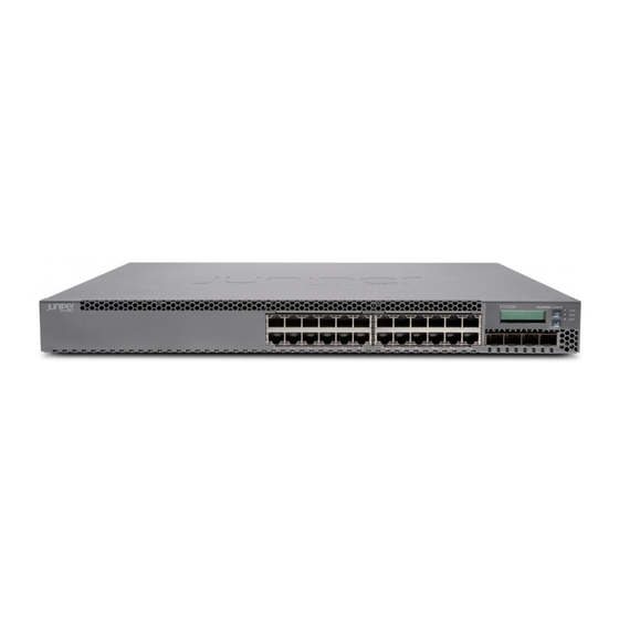
EX3300 Quick Start
IN THIS GUIDE
Step 1: Begin | 1
Step 2: Up and Running | 5
Step 3: Keep Going | 6
Step 1: Begin
IN THIS SECTION
Mount the EX3300 on Two Posts of a Rack | 2
Connect Power to the EX3300 | 2
To install and perform initial configuration of a Juniper Networks EX3300 Ethernet Switch, you need:
Two mounting brackets and eight mounting screws (provided)
Screws to secure the chassis to the rack or cabinet (not provided)
Phillips (+) screwdriver, number 2 (not provided)
For AC systems—an AC power cord with a plug appropriate for your geographical location and a power cord retainer—both
provided
For DC systems—DC power source cables (12–14 AWG—not provided) with ring lugs (Molex 0190700067 or
equivalent—not provided) attached
For grounding the switch—a grounding cable (minimum 14 AWG (2 mm²), minimum 90°C wire), a grounding lug (Panduit
LCD6-14BH-L or equivalent), a pair of 10-32x.25-in. screws, and a pair of flat washers—none provided
Ethernet cable with an RJ-45 connector attached (provided)
Advertisement
Table of Contents

Related Manuals for Juniper EX3300


Summary of Contents for Juniper EX3300
- Page 1 Mount the EX3300 on Two Posts of a Rack | 2 Connect Power to the EX3300 | 2 To install and perform initial configuration of a Juniper Networks EX3300 Ethernet Switch, you need: Two mounting brackets and eight mounting screws (provided)
- Page 2 RJ-45 to DB-9 serial port adapter (provided) Management host, such as a PC, with an Ethernet port (not provided) Mount the EX3300 on Two Posts of a Rack Two people are required for this procedure. 1. Place the rack or cabinet in its permanent location, allowing adequate clearance for airflow and maintenance, and secure it to the building structure.
- Page 3 AC power outlet using the power cord. Connecting EX3300 to AC power The AC power supply has a power cord inlet on the rear panel. 1. Squeeze the sides of the power cord retainer clip and insert the L-shaped ends of the wire clip into the holes in the brackets next to the power cord inlet on the rear panel.
- Page 4 Connecting EX3300 to DC power The DC power supply has four terminals labeled A+, B+, A–, and B– on the rear panel, covered by a clear plastic cover. WARNING: Ensure that the input circuit breaker is open so that the cable leads will not become active while you are connecting DC power.
-
Page 5: Step 2: Up And Running
To run the ezsetup script, the switch must have the factory default configuration as the active configuration. If you have configured anything on the switch and want to run ezsetup, revert to the factory default configuration. For information about reverting to the factory default configuration, see the EX3300 documentation at https://www.juniper.net/documentation/product/en_US/ex3300. - Page 6 You can now log in with the CLI to continue configuring the switch. Step 3: Keep Going IN THIS SECTION Safety Warnings Summary | 7 Power Cable Warning (Japanese) | 7 Contacting Juniper Networks | 8...
-
Page 7: Safety Warnings Summary
Before connecting the switch to a power source, read the installation instructions in the EX Series documentation. Installing an EX3300 switch requires one person to lift the switch and a second person to install the mounting screws. If the rack has stabilizing devices, install them in the rack before mounting or servicing the switch in the rack. -
Page 8: Contacting Juniper Networks
For technical support, see: http://www.juniper.net/support/requesting-support.html Juniper Networks, the Juniper Networks logo, Juniper, and Junos are registered trademarks of Juniper Networks, Inc. in the United States and other countries. All other trademarks, service marks, registered marks, or registered service marks are the property of their respective owners.