Juniper EX3300 Series Complete Hardware Manual
Hide thumbs
Also See for EX3300 Series:
- Hardware manual (272 pages) ,
- Complete hardware manual (218 pages) ,
- Quick start manual (8 pages)

Related Manuals for Juniper EX3300 Series


Summary of Contents for Juniper EX3300 Series
- Page 1 Complete Hardware Guide for EX3300 Ethernet Switches Model name: EX3300 Series Ethernet Switch Published: 2011-09-15 Revision 1 Copyright © 2011, Juniper Networks, Inc.
- Page 2 Products made or sold by Juniper Networks or components thereof might be covered by one or more of the following patents that are owned by or licensed to Juniper Networks: U.S. Patent Nos. 5,473,599, 5,905,725, 5,909,440, 6,192,051, 6,333,650, 6,359,479, 6,406,312, 6,429,706, 6,459,579, 6,493,347, 6,538,518, 6,538,899, 6,552,918, 6,567,902, 6,578,186, and 6,590,785.
- Page 3 Juniper, even if such feature, function, service, application, operation, or capability is enabled without a key; (g) distribute any key for the Software provided by Juniper to any third party; (h) use the...
- Page 4 Customer did not originally purchase from Juniper or an authorized Juniper reseller; (k) disclose the results of testing or benchmarking of the Software to any third party without the prior written consent of Juniper; or (l) use the Software in any manner other than as expressly provided herein.
- Page 5 (or services are accessed by) the Software shall be a third party beneficiary with respect to this Agreement, and such licensor or vendor shall have the right to enforce this Agreement in its own name as if it were Juniper. In addition, certain third party software may be provided with the Software and is subject to the accompanying license(s), if any, of its respective owner(s).
- Page 6 Copyright © 2011, Juniper Networks, Inc.
-
Page 7: Table Of Contents
Console Port Connector Pinout Information for an EX Series Switch ..27 Management Port Connector Pinout Information for an EX3300 Switch ..28 Copyright © 2011, Juniper Networks, Inc. - Page 8 Connecting Earth Ground to an EX2200, EX3200, or EX3300 Switch ..84 Connecting Earth Ground to an EX4200 Switch ..... . . 85 viii Copyright © 2011, Juniper Networks, Inc.
- Page 9 Packing a Switch for Shipping ........129 Packing Switch Components for Shipping ......129 Copyright © 2011, Juniper Networks, Inc.
- Page 10 United States ..........177 Copyright © 2011, Juniper Networks, Inc.
- Page 11 Compliance Statements for Acoustic Noise for EX Series Switches ..178 Declaration of Conformity for EX3300 Switches ......179 Copyright © 2011, Juniper Networks, Inc.
- Page 12 Complete Hardware Guide for EX3300 Ethernet Switches Copyright © 2011, Juniper Networks, Inc.
- Page 13 Installing the Switch ..........65 Copyright © 2011, Juniper Networks, Inc.
- Page 14 Power and Electrical Safety Information ......157 Figure 47: Place a Component into an Antistatic Bag ..... . 159 Copyright © 2011, Juniper Networks, Inc.
- Page 15 Planning Power Requirements ........55 Copyright © 2011, Juniper Networks, Inc.
- Page 16 Table 28: Port Settings ..........101 Copyright © 2011, Juniper Networks, Inc.
-
Page 17: About This Topic Collection
Component descriptions, site preparation, installation, replacement, and safety and compliance information for EX3200 Ethernet switches Complete Hardware Guide for EX3300 Ethernet Switches Component descriptions, site preparation, installation, replacement, and safety and compliance information for EX3300 Ethernet switches Copyright © 2011, Juniper Networks, Inc. xvii... - Page 18 OS for EX Series Ethernet Switches, Release 11.3: Ethernet Switching ® Junos OS for EX Series Ethernet Switches, Release 11.3: EX3300, EX4200, and EX4500 Virtual Chassis ® Junos OS for EX Series Ethernet Switches, Release 11.3: EX8200 Virtual Chassis xviii Copyright © 2011, Juniper Networks, Inc.
-
Page 19: Downloading Software
OS for EX Series Ethernet Switches, Release 11.3: User Interfaces Downloading Software You can download Junos OS for EX Series switches from the Download Software area . To download the software, you must http://www.juniper.net/customers/support/ Copyright © 2011, Juniper Networks, Inc. -
Page 20: Documentation Symbols Key
Complete Hardware Guide for EX3300 Ethernet Switches have a Juniper Networks user account. For information about obtaining an account, see http://www.juniper.net/entitlement/setupAccountInfo.do Documentation Symbols Key Notice Icons Icon Meaning Description Informational note Indicates important features or instructions. Caution Indicates a situation that might result in loss of data or hardware damage. -
Page 21: Documentation Feedback
We encourage you to provide feedback, comments, and suggestions so that we can improve the documentation. Send e-mail to techpubs-comments@juniper.net with the following: Document URL or title Page number if applicable Software version Your name and company Copyright © 2011, Juniper Networks, Inc. -
Page 22: Requesting Technical Support
7 days a week, 365 days a year. Self-Help Online Tools and Resources For quick and easy problem resolution, Juniper Networks has designed an online self-service portal called the Customer Support Center (CSC) that provides you with the following features: Find CSC offerings: http://www.juniper.net/customers/support/... -
Page 23: Switch And Components Overview And Specifications
PART 1 Switch and Components Overview and Specifications EX3300 Switch Overview on page 3 Component Descriptions on page 11 Component Specifications on page 25 Copyright © 2011, Juniper Networks, Inc. - Page 24 Complete Hardware Guide for EX3300 Ethernet Switches Copyright © 2011, Juniper Networks, Inc.
-
Page 25: Ex3300 Switch Overview
Layer 2 and Layer 3 switching, routing, and security services. The same Junos OS code base that runs on EX Series switches also runs on all Juniper Networks J Series, M Series, MX Series, and T Series routers and SRX Series services gateways. -
Page 26: Uplink Ports
The EX3300 switch models are available: With 24 or 48 network ports With or without PoE+ capability With front-to-back or back-to-front airflow With AC or DC power supplies Table 1 on page 5 lists the EX3300 switch models. Copyright © 2011, Juniper Networks, Inc. -
Page 27: Chassis Physical Specifications For Ex3300 Switches
EX3300-48T-BF: 10.8 lb (4.9 kg) EX3300-48P: 12.8 lb (5.8 kg) Related Rack Requirements for EX3300 Switches on page 47 Documentation Cabinet Requirements for EX3300 Switches on page 48 Mounting an EX3300 Switch on page 68 Copyright © 2011, Juniper Networks, Inc. -
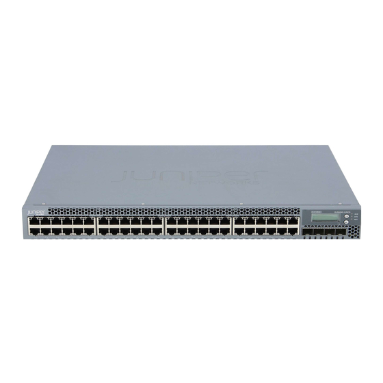
Page 28: Front Panel Of An Ex3300 Switch
EX3300 switch with 24 Gigabit Ethernet ports. Figure 1: Front Panel of an EX3300 Switch with 48 Gigabit Ethernet Ports LCD panel Menu button Chassis EX3300 PoE+ status LEDs Network ports SFP+ uplink ports Enter button Copyright © 2011, Juniper Networks, Inc. -
Page 29: Rear Panel Of An Ex3300 Switch
AC power cord inlet or DC power terminal block Figure 3 on page 8 shows the rear panel of an EX3300 switch with AC power supply. The power cord retainer extends out of the chassis by 3 in. (7.62 cm). Copyright © 2011, Juniper Networks, Inc. -
Page 30: Ex3300 Switch Hardware And Cli Terminology Mapping
EX3300 Switch Hardware and CLI Terminology Mapping This topic describes the hardware terms used in EX3300 switch documentation and the corresponding terms used in the Junos OS command line interface (CLI). See Table 3 on page Copyright © 2011, Juniper Networks, Inc. -
Page 31: Table 3: Cli Equivalents Of Terms Used In Documentation For Ex3300
24x 10/100/1000 the switch page 6 BASE-T 48x 10/100/1000 BASE-T 4x GE/XE SFP+ PIC 1 Built-in uplink ports on “Front Panel of an the front panel of the EX3300 Switch” on switch page 6 Copyright © 2011, Juniper Networks, Inc. - Page 32 Built-in fan tray – Fan tray “Cooling System and Airflow in an EX3300 Switch” on page 22 Related EX Series Switches Hardware and CLI Terminology Mapping Documentation EX3300 Switches Hardware Overview on page 3 Copyright © 2011, Juniper Networks, Inc.
-
Page 33: Component Descriptions
You can turn on the backlight by pressing the Menu Enter button once. After turning on the backlight, you can toggle between the LCD panel menus by pressing the Menu button and navigate through the menu options by pressing the button. Enter Copyright © 2011, Juniper Networks, Inc. -
Page 34: Lcd Panel Modes
Version of Junos OS for EX Series switches loaded on the switch In the maintenance mode, the second line displays one of the following options that you can use to configure and troubleshoot the switch: System halt System reboot Load rescue Copyright © 2011, Juniper Networks, Inc. -
Page 35: Lcd Panel Menus
POE (Power over Ethernet) “Network Port and Uplink Port LEDs in EX3300 Switches” on page 17 for information on the Status LED modes. Press to exit the Idle menu and go to the Status menu. Menu Copyright © 2011, Juniper Networks, Inc. - Page 36 This option is available only for an EX3300 switch that is a member of a Virtual Chassis configuration. If you do not want users to use Status menu options, disable the entire menu or individual menu options. See Configuring the LCD Panel on EX Series Switches (CLI Procedure). Copyright © 2011, Juniper Networks, Inc.
- Page 37 See Configuring the LCD Panel on EX Series Switches (CLI Procedure). Related Front Panel of an EX3300 Switch on page 6 Documentation Connecting and Configuring an EX Series Switch (CLI Procedure) on page 110 Copyright © 2011, Juniper Networks, Inc.
-
Page 38: Chassis Status Leds In Ex3300 Switches
SYS (System) Green On steadily—Junos OS for EX Series switches has been loaded on the switch. Blinking—The switch is booting. Copyright © 2011, Juniper Networks, Inc. -
Page 39: Network Port And Uplink Port Leds In Ex3300 Switches
Figure 7: LEDs on the Network Ports on the Front Panel Link/Activity LED Status LED Figure 8: LEDs on the Uplink Ports Port 0 Port 1 EX3300 PoE+ Status Link/Activity Port 2 Port 3 Copyright © 2011, Juniper Networks, Inc. -
Page 40: Table 6: Link/Activity Led On The Network Ports And Uplink Ports In Ex3300
Power over Ethernet Plus (PoE+) status. From the Idle menu of the LCD, use the button on the LCD panel to toggle between the SPD, ADM, DPX, and POE, indicators. Enter Table 7 on page 19 describes the Status LED. Copyright © 2011, Juniper Networks, Inc. -
Page 41: Table 7: Status Led On The Network Ports And Uplink Ports In Ex3300
Unlit—PoE is not enabled on the port. Related Front Panel of an EX3300 Switch on page 6 Documentation Configuring Gigabit Ethernet Interfaces (CLI Procedure) Copyright © 2011, Juniper Networks, Inc. -
Page 42: Management Port Leds In Ex3300 Switches
Indicates the duplex mode. The status indicators are: On steadily—Port is set to full-duplex mode. Off—Port is set to half-duplex mode. Related Connecting an EX Series Switch to a Network for Out-of-Band Management on page 95 Documentation Copyright © 2011, Juniper Networks, Inc. -
Page 43: Power Supply In Ex3300 Switches
Power Specifications for EX3300 Switches on page 55 Connecting AC Power to an EX3300 Switch on page 91 Connecting DC Power to an EX3300 Switch on page 92 Connecting Earth Ground to an EX Series Switch on page 83 Copyright © 2011, Juniper Networks, Inc. -
Page 44: Cooling System And Airflow In An Ex3300 Switch
Hot air exhausts from the rear of the chassis. See Figure 10 on page Figure 10: Front-to-Back Airflow Through the EX3300 Switch Chassis Chassis front Air intake Air intake Air exhaust Fan air exhaust Chassis rear Copyright © 2011, Juniper Networks, Inc. -
Page 45: Figure 11: Back-To-Front Airflow Through The Ex3300 Switch Chassis
Rear Panel of an EX3300 Switch on page 7 Documentation Chassis Status LEDs in EX3300 Switches on page 16 Understanding Alarm Types and Severity Levels on EX Series Switches Prevention of Electrostatic Discharge Damage on page 158 Copyright © 2011, Juniper Networks, Inc. - Page 46 Complete Hardware Guide for EX3300 Ethernet Switches Copyright © 2011, Juniper Networks, Inc.
-
Page 47: Component Specifications
SFP+ Direct Attach Cables for EX Series Switches on page 35 USB Port Specifications for an EX Series Switch The following Juniper Networks USB flash drives have been tested and are officially supported for the USB port on all EX Series switches:... -
Page 48: Network Port Connector Pinout Information For An Ex3300 Switch
Positive Vport (in PoE models) TRP3+ Transmit/receive data pair 3 TRP3- Transmit/receive data pair 3 TRP2- Transmit/receive data pair 2 Positive Vport (in PoE models) TRP4+ Transmit/receive data pair 4 TRP4- Transmit/receive data pair 4 Copyright © 2011, Juniper Networks, Inc. -
Page 49: Console Port Connector Pinout Information For An Ex Series Switch
See Rear Panel of an EX3200 Switch for port location. Rear Panel of an EX3300 Switch on page 7 for port location. See Rear Panel of an EX4200 Switch for port location. See Front Panel of an EX4500 Switch for port location. Copyright © 2011, Juniper Networks, Inc. -
Page 50: Management Port Connector Pinout Information For An Ex3300 Switch
Transmit/receive data pair 4 This pin is used only when the port is operating at 1000 Mbps. TRP4- Transmit/receive data pair 4 This pin is used only when the port is operating at 1000 Mbps. Copyright © 2011, Juniper Networks, Inc. -
Page 51: Optical Interface Support In Ex3300 Switches
NOTE: Use only optical transceivers and optical connectors purchased from Juniper Networks for your EX Series switches. The Gigabit Ethernet SFP and SFP+ transceivers installed in EX3300 switches support digital optical monitoring (DOM): you can view the diagnostic details for these transceivers... -
Page 52: Table 15: Optical Interface Support For Gigabit Ethernet Sfp Transceivers
500 MHz/km Distance 220 m 275 m 500 m 550 m (722 ft) (902 ft) (1640 ft) (1804 ft) DOM Support Available Software Required Junos OS for EX Series switches, Release 11.3 or later Copyright © 2011, Juniper Networks, Inc. - Page 53 Maximum Input Power –3 dBm Fiber Type Core/Cladding Size 9/125 µm Modal Bandwidth – Distance 10 km (6.2 miles) DOM Support Available Software Required Junos OS for EX Series switches, Release 11.3 or later Copyright © 2011, Juniper Networks, Inc.
-
Page 54: Table 16: Optical Interface Support For Sfp+ Gigabit Ethernet Transceivers
Modal Bandwidth 1500 MHz/km MHz/km MHz/km Distance 10 m 30 m 100 m (32.8 ft) (98.4 ft) (328 ft) DOM Support Available Software Required Junos OS for EX Series switches, Release 11.3 or later Copyright © 2011, Juniper Networks, Inc. - Page 55 26 m 33 m 66 m 82 m 300 m (85 ft) (108 ft) (216 ft) (269 ft) (984 ft) DOM Support Available Software required Junos OS for EX Series switches, Release 11.3 or later Copyright © 2011, Juniper Networks, Inc.
- Page 56 FDDI/OM1 Modal Bandwidth MHz/km MHz/km MHz/km Distance 220 m 220 m 220 m (722 ft) (722 ft) (722 ft) DOM Support Available Software required Junos OS for EX Series switches, Release 11.3 or later Copyright © 2011, Juniper Networks, Inc.
-
Page 57: Sfp+ Direct Attach Cables For Ex Series Switches
Twinax cables, are suitable for in-rack connections between servers and switches. They are suitable for short distances up to 7 m, making them ideal for highly cost-effective networking connectivity within a rack and between adjacent racks. Copyright © 2011, Juniper Networks, Inc. -
Page 58: Cable Specifications
Standards Supported by These Cables on page 37 Cable Specifications Juniper Networks SFP+ direct attach cables are available in four lengths: 1 m (3.3 ft)—Supported on SFP+ uplink module ports in EX3200, EX4200, and EX4500 switches, on uplink ports in EX3300 switches, and on 8-port SFP+ line cards and 40-port SFP+ line cards in EX8200 switches 3 m (9.9 ft)—Supported on SFP+ uplink module ports in EX3200, EX4200, and EX4500... -
Page 59: Standards Supported By These Cables
EX-SFP-10GE-DAC-5m—5 m (16.4 ft) EX-SFP-10GE-DAC-7m—7 m (23 ft) Standards Supported by These Cables The cables comply with the following standards: SFP mechanical standard SFF-843—see ftp://ftp.seagate.com/sff/SFF-8431.PDF Electrical interface standard SFF-8432—see ftp://ftp.seagate.com/sff/SFF-8432.PDF SFP+ Multi-Source Alliance (MSA) standards Copyright © 2011, Juniper Networks, Inc. - Page 60 Optical Interface Support in EX4500 Switches Optical Interface Support in EX8200 Switches Installing a Transceiver in an EX Series Switch on page 79 Removing a Transceiver from an EX Series Switch on page 115 Copyright © 2011, Juniper Networks, Inc.
-
Page 61: Planning For Switch Installation
Planning for Switch Installation Site Preparation on page 41 Mounting and Clearance Requirements on page 47 Cable Specifications on page 53 Planning Power Requirements on page 55 Planning the Virtual Chassis on page 59 Copyright © 2011, Juniper Networks, Inc. - Page 62 Complete Hardware Guide for EX3300 Ethernet Switches Copyright © 2011, Juniper Networks, Inc.
-
Page 63: Site Preparation
Calculate the power consumption and “Power Specifications for EX3300 requirements. Switches” on page 55 Hardware Configuration Choose the number and types of switches you “EX3300 Switches Hardware want to install. Overview” on page 3 Rack or Cabinet Copyright © 2011, Juniper Networks, Inc. -
Page 64: General Site Guidelines
General Site Guidelines This topic applies to hardware devices in the EX Series product family, which includes switches and the XRE200 External Routing Engine. This topic also applies to hardware devices in the QFX Series. Copyright © 2011, Juniper Networks, Inc. -
Page 65: Site Electrical Wiring Guidelines
XRE200 External Routing Engine. This topic also applies to hardware devices in the QFX Series. Table 20 on page 44 describes the factors you must consider while planning the electrical wiring at your site. Copyright © 2011, Juniper Networks, Inc. -
Page 66: Table 20: Site Electrical Wiring Guidelines
AC Power Supply in an EX6200 Switch DC Power Supply in an EX6200 Switch AC Power Supply in an EX8200 Switch DC Power Supply in an EX8200 Switch AC Power Supply in a QFX3500 Switch Copyright © 2011, Juniper Networks, Inc. -
Page 67: Environmental Requirements And Specifications For Ex Series Switches
40° C) XRE200 External Routing Engines: Normal operation ensured in temperature range of 41° F through 104° F (5° C through 40° C) Seismic Complies with Zone 4 earthquake requirements as per GR-63, Issue Copyright © 2011, Juniper Networks, Inc. - Page 68 Clearance Requirements for Airflow and Hardware Maintenance for EX4500 Switches Clearance Requirements for Airflow and Hardware Maintenance for an EX6210 Switch Clearance Requirements for Airflow and Hardware Maintenance for an EX8208 Switch Clearance Requirements for Airflow and Hardware Maintenance for an EX8216 Switch Copyright © 2011, Juniper Networks, Inc.
-
Page 69: Mounting And Clearance Requirements
The holes in the mounting brackets are spaced at 1 U (1.75 in. or 4.45 cm), so that the switch can spacing be mounted in any rack that provides holes spaced at that distance. Copyright © 2011, Juniper Networks, Inc. -
Page 70: Cabinet Requirements For Ex3300 Switches
You can mount the switch in a cabinet that contains a 19-in. rack. Cabinet requirements consist of: Cabinet size Clearance requirements Cabinet airflow requirements Table 23 on page 49 provides the cabinet requirements and specifications for the switch. Copyright © 2011, Juniper Networks, Inc. -
Page 71: Table 23: Cabinet Requirements And Specifications For The Switch
Rack-Mounting and Cabinet-Mounting Warnings on page 146 Mounting an EX3300 Switch on Two Posts in a Rack or Cabinet on page 68 Mounting an EX3300 Switch on Four Posts in a Rack or Cabinet on page 71 Copyright © 2011, Juniper Networks, Inc. -
Page 72: Requirements For Mounting An Ex3300 Switch On A Desktop Or Wall
Insert the screws into wall studs wherever possible to provide added support for the chassis. Use the wall-mount kit from Juniper Networks to mount the switch on a wall. The wall-mount kit is not part of the standard package and must be ordered separately. -
Page 73: Figure 13: Front-To-Back Airflow Through The Ex3300 Switch Chassis
Figure 13: Front-to-Back Airflow Through the EX3300 Switch Chassis Chassis front Air intake Air intake Air exhaust Fan air exhaust Chassis rear Figure 14 on page 52 shows airflow through a back-to-front airflow model. Copyright © 2011, Juniper Networks, Inc. -
Page 74: Figure 14: Back-To-Front Airflow Through The Ex3300 Switch Chassis
Rack Requirements for EX3300 Switches on page 47 Documentation Cabinet Requirements for EX3300 Switches on page 48 General Site Guidelines on page 42 Rack-Mounting and Cabinet-Mounting Warnings on page 146 Cooling System and Airflow in an EX3300 Switch on page 22 Copyright © 2011, Juniper Networks, Inc. -
Page 75: Cable Specifications
Management Port Connector Pinout Information for an EX3300 Switch on page 28 Documentation Console Port Connector Pinout Information for an EX Series Switch on page 27 Front Panel of an EX3300 Switch on page 6 Rear Panel of an EX3300 Switch on page 7 Copyright © 2011, Juniper Networks, Inc. - Page 76 Complete Hardware Guide for EX3300 Ethernet Switches Copyright © 2011, Juniper Networks, Inc.
-
Page 77: Planning Power Requirements
Table 25: DC Power Supply Electrical Specifications for EX3300 Switches Item Specification DC input voltage 43 through 75 VDC DC input current 2 A maximum Power supply output 100 W Output holdup time 1 ms minimum Copyright © 2011, Juniper Networks, Inc. -
Page 78: Ac Power Cord Specifications For Ex3300 Switches
250 VAC, 10 A, 50 Hz GB2099 and GB1002 Europe (except Italy, Switzerland, and 250 VAC, 10 A, 50 Hz CEE (7) VII United Kingdom) Italy 250 VAC, 10 A, 50 Hz CEI 23-16 Copyright © 2011, Juniper Networks, Inc. -
Page 79: Figure 15: Ac Plug Types
Power Supply in EX3300 Switches on page 21 Documentation General Safety Guidelines and Warnings on page 133 General Electrical Safety Guidelines and Warnings on page 157 Prevention of Electrostatic Discharge Damage on page 158 Copyright © 2011, Juniper Networks, Inc. - Page 80 Complete Hardware Guide for EX3300 Ethernet Switches Copyright © 2011, Juniper Networks, Inc.
-
Page 81: Planning The Virtual Chassis
Virtual Chassis Cabling Configuration Examples for EX3300 Switches on page 60 Understanding EX3300 Virtual Chassis Hardware Configuration Virtual Chassis is a feature in Juniper Networks EX3300 Ethernet Switches that allows you to interconnect two or more EX3300 switches, enabling them to operate as a unified, single, high bandwidth switch. -
Page 82: Planning Ex3300 Virtual Chassis
EX3300 switch is 6.2 miles (10 km). The following illustrations show various Virtual Chassis cabling configuration examples. NOTE: For increased availability and redundancy, we recommend that you always configure your Virtual Chassis in a ring topology. Copyright © 2011, Juniper Networks, Inc. -
Page 83: Figure 16: Ex3300 Switches Mounted On A Single Rack And Connected In A Ring
EX3300 PoE+ EX3300 PoE+ EX3300 PoE+ Figure 17: EX3300 Switches Mounted on a Single Rack and Connected in a Ring Topology: Option 2 EX3300 PoE+ EX3300 PoE+ EX3300 PoE+ EX3300 PoE+ EX3300 PoE+ EX3300 PoE+ Copyright © 2011, Juniper Networks, Inc. -
Page 84: Figure 18: Ex3300 Switches Mounted On A Single Rack And Connected In A Ring
Ring Topology Using Medium and Long Cables: Option 2 EX3300 PoE+ EX3300 PoE+ Related Understanding EX3300 Virtual Chassis Hardware Configuration on page 59 Documentation Understanding EX3300, EX4200, and EX4500 Virtual Chassis Components Planning EX3300 Virtual Chassis on page 60 Copyright © 2011, Juniper Networks, Inc. -
Page 85: Installing And Connecting The Switch And Switch Components
PART 3 Installing and Connecting the Switch and Switch Components Installing the Switch on page 65 Installing Switch Components on page 79 Connecting the Switch on page 83 Performing Initial Configuration on page 105 Copyright © 2011, Juniper Networks, Inc. - Page 86 Complete Hardware Guide for EX3300 Ethernet Switches Copyright © 2011, Juniper Networks, Inc.
-
Page 87: Installing The Switch
(using the rubber feet provided) “Mounting an EX3300 Switch on a Wall” on page 75 (using the separately orderable wall-mount kit) Follow instructions in “Connecting Earth Ground to an EX Series Switch” on page Copyright © 2011, Juniper Networks, Inc. -
Page 88: Unpacking An Ex3300 Switch
Save the shipping carton and packing materials in case you need to move or ship the switch later. Related Mounting an EX3300 Switch on page 68 Documentation Installing and Connecting an EX3300 Switch on page 65 Copyright © 2011, Juniper Networks, Inc. -
Page 89: Parts Inventory (Packing List) For An Ex3300 Switch
If any part on the packing list is missing, contact your customer service representative or contact Juniper customer care from within the U.S. or Canada by telephone at 1–800–638–8296. For international-dial or direct-dial options in countries without toll-free numbers, see http://www.juniper.net/support/requesting-support.html... -
Page 90: Mounting An Ex3300 Switch
You can mount the switch on four posts of a four-post rack by using the mounting brackets provided with the separately orderable four-post rack-mount kit. See “Mounting an EX3300 Switch on Four Posts in a Rack or Cabinet” on page Copyright © 2011, Juniper Networks, Inc. - Page 91 Align the mounting brackets along the front or rear of the side panels of the switch chassis depending on how you want to mount the switch. For example, if you want to front-mount the switch, align the brackets along the front of the chassis. See Figure 21 on page Copyright © 2011, Juniper Networks, Inc.
-
Page 92: Figure 21: Attaching The Mounting Bracket Along The Front Of The Switch
Have a second person secure the switch to the rack by using the appropriate screws. Tighten the screws. Ensure that the switch chassis is level by verifying that all screws on one side of the rack are aligned with the screws on the other side. Copyright © 2011, Juniper Networks, Inc. -
Page 93: Mounting An Ex3300 Switch On Four Posts In A Rack Or Cabinet
One pair each of flush or 2-in.-recess front brackets One pair of side-rail brackets One pair of rear brackets Screws to secure the chassis and the rear brackets to the rack (not provided) Copyright © 2011, Juniper Networks, Inc. -
Page 94: Figure 23: Attaching The Front Bracket To The Side-Rail Bracket
Ensure that the two holes in the rear of the side-rail brackets are aligned with the remaining two holes in the side panel. See Figure 24 on page Figure 24: Attaching the Side-Rail Bracket to the Switch Chassis Copyright © 2011, Juniper Networks, Inc. -
Page 95: Figure 25: Mounting The Switch To The Front Posts In A Rack
Attach the rear brackets to the rear post by using the appropriate screws for your rack. Tighten the screws. Ensure that the switch chassis is level by verifying that all the screws on the front of the rack are aligned with the screws at the back of the rack. Copyright © 2011, Juniper Networks, Inc. -
Page 96: Mounting An Ex3300 Switch In A Recessed Position In A Rack Or Cabinet
Read “General Safety Guidelines and Warnings” on page 133, with particular attention “Chassis Lifting Guidelines for EX3300 Switches” on page 144. Ensure that you have the following parts and tools available: Copyright © 2011, Juniper Networks, Inc. -
Page 97: Mounting An Ex3300 Switch On A Wall
Install the wall-mount baffle above the units to reduce the risk of objects or substances falling into the air exhaust or power supply, which could cause a fire. Copyright © 2011, Juniper Networks, Inc. -
Page 98: Figure 28: Attaching Wall-Mount Brackets To A Switch Chassis
Install six mounting screws in the wall for the wall-mount brackets and baffle as shown in Figure 29 on page Use hollow wall anchors rated to support up to 75 lb (34 kg) if you are not inserting the mounting screws directly into wall studs. Copyright © 2011, Juniper Networks, Inc. -
Page 99: Figure 29: Measurements For Installing Mounting Screws
Lift the unit (one switch or two) by grasping each side, and hang the unit by attaching the brackets to the mounting screws as shown in Figure 30 on page Tighten all mounting screws. Copyright © 2011, Juniper Networks, Inc. -
Page 100: Figure 30: Mounting The Switch On A Wall
Connecting AC Power to an EX3300 Switch on page 91 Documentation Connecting DC Power to an EX3300 Switch on page 92 Connecting and Configuring an EX Series Switch (CLI Procedure) on page 110 Wall-Mounting Warning for EX3300 Switches on page 150 Copyright © 2011, Juniper Networks, Inc. -
Page 101: Installing Switch Components
After you insert a transceiver or when you change the media-type configuration, wait for 6 seconds for the interface to appear in operational commands. Use only optical transceivers and optical connectors purchased from Juniper Networks for your EX Series switches. NOTE:... -
Page 102: Figure 31: Installing A Transceiver In An Ex Series Switch
Do not look directly into a fiber-optic transceiver or into the ends of fiber-optic cables. Fiber-optic transceivers and fiber-optic cables connected to transceivers emit laser light that can damage your eyes. Figure 31: Installing a Transceiver in an EX Series Switch Copyright © 2011, Juniper Networks, Inc. - Page 103 Optical Interface Support in EX3200 Switches Optical Interface Support in EX3300 Switches on page 29 Optical Interface Support in EX4200 Switches Optical Interface Support in EX4500 Switches Optical Interface Support in EX6200 Switches Optical Interface Support in EX8200 Switches Copyright © 2011, Juniper Networks, Inc.
- Page 104 Complete Hardware Guide for EX3300 Ethernet Switches Copyright © 2011, Juniper Networks, Inc.
-
Page 105: Connecting The Switch
Figure 32: Connecting a Grounding Cable to an EX Series Switch Before you connect earth ground to the protective earthing terminal of an EX Series switch, ensure that a licensed electrician has attached an appropriate grounding lug to the grounding cable. Copyright © 2011, Juniper Networks, Inc. -
Page 106: Connecting Earth Ground To An Ex2200, Ex3200, Or Ex3300 Switch
NOTE: Some early models of EX3200 switches require 10-24x.25-in. screws rather than 10-32x.25-in. screws. If the Juniper Networks product number on the label next to the protective earthing terminal is from 750-021xxx through 750-030xxx, the switch requires 10-24x.25-in. screws. -
Page 107: Connecting Earth Ground To An Ex4200 Switch
NOTE: Some early models of EX4200 switches require 10-24x.25-in. screws rather than 10-32x.25-in. screws. If the Juniper Networks product number on the label next to the protective earthing terminal is from 750-021xxx through 750-030xxx, the switch requires 10-24x.25-in. screws. -
Page 108: Connecting Earth Ground To An Ex4500 Switch
See Mounting an EX4500 Switch on Four Posts in a Rack or Cabinet Ensure that you have the following parts and tools available: Copyright © 2011, Juniper Networks, Inc. -
Page 109: Connecting Earth Ground To An Ex6210 Switch
The protective earthing terminal is located on the rear of the chassis on the lower left side in an EX6210 switch. See Figure 34 on page 88 for the location of the earthing terminal on an Ex6210 switch. Copyright © 2011, Juniper Networks, Inc. -
Page 110: Figure 34: Location Of Protective Earthing Terminal On An Ex6210 Switch
Specifications for EX6200 Switches. Two ¼-20x0.5-in. screws and two flat washers to secure the grounding lug to the protective earthing terminal (provided) Phillips (+) screwdriver, number 2 (not provided) To connect earth ground to an EX6210 switch: Copyright © 2011, Juniper Networks, Inc. -
Page 111: Connecting Earth Ground To An Ex8208 Switch
There are two protective earthing terminals on an EX8216 switch: one on the left side of the chassis and the other on the rear of the chassis. Only one of the two protective earthing terminals needs to be permanently connected to earth ground. Copyright © 2011, Juniper Networks, Inc. - Page 112 Connecting DC Power to an EX4500 Switch Connecting AC Power to an EX6200 Switch Connecting DC Power to an EX6200 Switch Connecting AC Power to an EX8200 Switch Connecting DC Power to an EX8200 Switch Copyright © 2011, Juniper Networks, Inc.
-
Page 113: Connecting Ac Power To An Ex3300 Switch
Turn the nut until it is tight against the base of the coupler and the slot in the nut is turned 90° from the top of the switch (see Figure 36 on page 92). If the AC power source outlet has a power switch, set it to the OFF (0) position. Copyright © 2011, Juniper Networks, Inc. -
Page 114: Connecting Dc Power To An Ex3300 Switch
For installations that require a separate grounding conductor to the chassis, use the protective earthing terminal on Copyright © 2011, Juniper Networks, Inc. - Page 115 Connect the power supply to the power sources. Secure power source cables to the power supply by screwing the ring lugs attached to the cables to the appropriate terminals by using the screw from the terminals (see Figure 37 on page 94). Copyright © 2011, Juniper Networks, Inc.
-
Page 116: Figure 37: Securing Ring Lugs To The Terminals On The Dc Power Supply
Hook the plastic cover on one side of the terminal block and gently flex it inwards to hook it on the other side also. Close the input circuit breaker. Related Connecting and Configuring an EX Series Switch (CLI Procedure) on page 110 Documentation Copyright © 2011, Juniper Networks, Inc. -
Page 117: Connecting An Ex Series Switch To A Network For Out-Of-Band Management
See Switch Fabric and Routing Engine (SRE) Module in an EX8208 Switch. See Routing Engine (RE) Module in an EX8216 Switch. See Front Panel of an XRE200 External Routing Engine. Connect the other end of the Ethernet cable to the management device. Copyright © 2011, Juniper Networks, Inc. -
Page 118: Connecting An Ex Series Switch To A Management Console
Console. Connecting an EX Series Switch to a Management Console Using RJ-45 Console Port on page 97 Connecting an EX2200 Series Switch to a Management Console Using Mini-USB Type-B Console Port on page 98 Copyright © 2011, Juniper Networks, Inc. -
Page 119: Console Port
See Switch Fabric and Routing Engine (SRE) Module in an EX6200 Switch. See Switch Fabric and Routing Engine (SRE) Module in an EX8208 Switch. See Routing Engine (RE) Module in an EX8216 Switch. See Front Panel of an XRE200 External Routing Engine. Copyright © 2011, Juniper Networks, Inc. -
Page 120: Connecting An Ex2200 Series Switch To A Management Console Using Mini-Usb Type-B Console Port
Ensure that the prolific driver is installed on the host machine. You can download the prolific driver from http://www.juniper.net/support/products/junos/ww/11.3/ http://www.juniper.net/support/products/junos/dom/11.3/ Ensure that you have the following parts and tools available: Copyright © 2011, Juniper Networks, Inc. -
Page 121: Connecting An Ex Series Switch To A Modem
If your computer does not have a DB-9 male connector pin, a USB to DB-9 male adapter (not provided) An adapter to connect the RS-232 DB-25 connector on the modem to the RJ-45 to DB-9 adapter on the switch (not provided) Copyright © 2011, Juniper Networks, Inc. -
Page 122: Setting The Serial Console Speed For The Switch
Boot the software: loader> boot The boot process proceeds as normal and ends with a login prompt. Configuring the Modem Before you connect the modem, you must configure the modem with the required port settings. Copyright © 2011, Juniper Networks, Inc. -
Page 123: Table 28: Port Settings
You must set the serial port to the fixed speed so that the modem will not adjust the serial port speed to the negotiated line speed. To save the new modem settings, type at&w0 at the prompt. Press Enter. Copyright © 2011, Juniper Networks, Inc. -
Page 124: Connecting The Modem To The Console Port
See Switch Fabric and Routing Engine (SRE) Module in an EX8208 Switch. See Routing Engine (RE) Module in an EX8216 Switch. Connect the other end of the cable to the RJ-45 to DB-9 serial port adapter supplied with your switch. Copyright © 2011, Juniper Networks, Inc. -
Page 125: Connecting A Fiber-Optic Cable To An Ex Series Switch
If the fiber-optic cable connector is covered by a rubber safety cap, remove the cap. Save the cap. Remove the rubber safety cap from the optical transceiver. Save the cap. Insert the cable connector into the optical transceiver (see Figure 44 on page 104). Copyright © 2011, Juniper Networks, Inc. -
Page 126: Figure 44: Connecting A Fiber-Optic Cable To An Optical Transceiver Installed
Optical Interface Support in EX3200 Switches Optical Interface Support in EX3300 Switches on page 29 Optical Interface Support in EX4200 Switches Optical Interface Support in EX4500 Switches Optical Interface Support in EX6200 Switches Optical Interface Support in EX8200 Switches Copyright © 2011, Juniper Networks, Inc. -
Page 127: Performing Initial Configuration
If your model has 48 ports, the file contains more interfaces, which correspond to the additional network ports. If your model is not PoE+-capable, the file does not include the stanza. Copyright © 2011, Juniper Networks, Inc. - Page 128 { unit 0 { family ethernet-switching; ge-0/0/2 { unit 0 { family ethernet-switching; ge-0/0/3 { unit 0 { family ethernet-switching; ge-0/0/4 { unit 0 { family ethernet-switching; ge-0/0/5 { unit 0 { Copyright © 2011, Juniper Networks, Inc.
- Page 129 { unit 0 { family ethernet-switching; ge-0/0/13 { unit 0 { family ethernet-switching; ge-0/0/14 { unit 0 { family ethernet-switching; ge-0/0/15 { unit 0 { family ethernet-switching; ge-0/0/16 { unit 0 { family ethernet-switching; Copyright © 2011, Juniper Networks, Inc.
- Page 130 { unit 0 { family ethernet-switching; ge-0/1/0 { unit 0 { family ethernet-switching; xe-0/1/0 { unit 0 { family ethernet-switching; ge-0/1/1 { unit 0 { family ethernet-switching; xe-0/1/1 { unit 0 { family ethernet-switching; Copyright © 2011, Juniper Networks, Inc.
- Page 131 { interface all; Related Configuration Files Terms Documentation Connecting and Configuring an EX Series Switch (CLI Procedure) on page 110 Understanding Configuration Files for EX Series Switches EX3300 Switches Hardware Overview on page 3 Copyright © 2011, Juniper Networks, Inc.
-
Page 132: Connecting And Configuring An Ex Series Switch (Cli Procedure)
See Reverting to the Default Factory Configuration for the EX Series Switch. Before you begin connecting and configuring an EX Series switch through the console using the CLI: Set the following parameter values in the console server or PC: Baud rate—9600 Flow control—None Data—8 Parity—None Copyright © 2011, Juniper Networks, Inc. - Page 133 Root login is allowed root only for SSH access. Use the Management Options page to select the management scenario: NOTE: On EX4500, EX6200, and EX8200 switches, only the out-of-band management option is available. Copyright © 2011, Juniper Networks, Inc.
- Page 134 Installing and Connecting an EX3300 Switch on page 65 Installing and Connecting an EX4200 Switch Installing and Connecting an EX4500 Switch Installing and Connecting an EX6210 Switch Installing and Connecting an EX8208 Switch Installing and Connecting an EX8216 Switch Copyright © 2011, Juniper Networks, Inc.
-
Page 135: Removing Switch Components
PART 4 Removing Switch Components Removing Switch Components on page 115 Copyright © 2011, Juniper Networks, Inc. - Page 136 Complete Hardware Guide for EX3300 Ethernet Switches Copyright © 2011, Juniper Networks, Inc.
-
Page 137: Removing Switch Components
To remove a transceiver from an EX Series switch: Place the antistatic bag or antistatic mat on a flat, stable surface. Label the cable connected to the transceiver so that you can reconnect it correctly. Copyright © 2011, Juniper Networks, Inc. - Page 138 Using your fingers, grasp the body of the transceiver and pull it straight out of the port. Place the transceiver in the antistatic bag or on the antistatic mat placed on a flat, stable surface. Place the dust cover over the empty port. Copyright © 2011, Juniper Networks, Inc.
-
Page 139: Disconnecting A Fiber-Optic Cable From An Ex Series Switch
“Laser and LED Safety Guidelines and Warnings for EX Series Switches” on page 139). Ensure that you have the following parts and tools available: A rubber safety cap to cover the transceiver A rubber safety cap to cover the fiber-optic cable connector Copyright © 2011, Juniper Networks, Inc. - Page 140 Optical Interface Support in EX3200 Switches Optical Interface Support in EX3300 Switches on page 29 Optical Interface Support in EX4200 Switches Optical Interface Support in EX4500 Switches Optical Interface Support in EX6200 Switches Optical Interface Support in EX8200 Switches Copyright © 2011, Juniper Networks, Inc.
-
Page 141: Switch And Component Maintenance
PART 5 Switch and Component Maintenance Routine Maintenance on page 121 Copyright © 2011, Juniper Networks, Inc. - Page 142 Complete Hardware Guide for EX3300 Ethernet Switches Copyright © 2011, Juniper Networks, Inc.
-
Page 143: Routine Maintenance
Fiber Cleaner. Follow the directions in the cleaning kit you use. Related Connecting a Fiber-Optic Cable to an EX Series Switch on page 103 Documentation Laser and LED Safety Guidelines and Warnings for EX Series Switches on page 139 Copyright © 2011, Juniper Networks, Inc. - Page 144 Optical Interface Support in EX3200 Switches Optical Interface Support in EX3300 Switches on page 29 Optical Interface Support in EX4200 Switches Optical Interface Support in EX4500 Switches Optical Interface Support in EX6200 Switches Optical Interface Support in EX8200 Switches Copyright © 2011, Juniper Networks, Inc.
-
Page 145: Returning Hardware
PART 6 Returning Hardware Returning the Switch or Switch Components on page 125 Copyright © 2011, Juniper Networks, Inc. - Page 146 Complete Hardware Guide for EX3300 Ethernet Switches Copyright © 2011, Juniper Networks, Inc.
-
Page 147: Returning The Switch Or Switch Components
Packing an EX3300 Switch or Component for Shipping on page 128 Returning an EX3300 Switch or Component for Repair or Replacement If you need to return an EX3300 switch or hardware component to Juniper Networks for repair or replacement, follow this procedure: Determine the serial number of the component. -
Page 148: Locating The Serial Number On An Ex3300 Switch Or Component
Complete Hardware Guide for EX3300 Ethernet Switches Locating the Serial Number on an EX3300 Switch or Component If you are returning an EX3300 switch or hardware component to Juniper Networks for repair or replacement, you must locate the serial number of the switch or component. -
Page 149: Locating The Chassis Serial Number Id Label On An Ex3300 Switch
Contacting Customer Support to Obtain Return Materials Authorization for EX Series Switches If you are returning a switch or hardware component to Juniper Networks for repair or replacement, obtain a Return Materials Authorization (RMA) from Juniper Networks Technical Assistance Center (JTAC). -
Page 150: Packing An Ex3300 Switch Or Component For Shipping
Returning an EX3300 Switch or Component for Repair or Replacement on page 125 Packing an EX3300 Switch or Component for Shipping If you are returning an EX3300 switch or component to Juniper Networks for repair or replacement, pack the item as described in this topic. -
Page 151: Packing A Switch For Shipping
To pack and ship switch components: Place individual components in antistatic bags. Ensure that the components are adequately protected with packing materials and packed so that the pieces are prevented from moving around inside the carton. Copyright © 2011, Juniper Networks, Inc. - Page 152 Close the top of the cardboard shipping carton and seal it with packing tape. Write the RMA number on the exterior of the carton to ensure proper tracking. Related Returning an EX3300 Switch or Component for Repair or Replacement on page 125 Documentation Copyright © 2011, Juniper Networks, Inc.
-
Page 153: Safety Information
PART 7 Safety Information General Safety Information on page 133 Radiation and Laser Warnings on page 139 Installation and Maintenance Safety Information on page 143 Power and Electrical Safety Information on page 157 Copyright © 2011, Juniper Networks, Inc. - Page 154 Complete Hardware Guide for EX3300 Ethernet Switches Copyright © 2011, Juniper Networks, Inc.
-
Page 155: General Safety Information
Do not perform any actions that create a potential hazard to people or make the equipment unsafe. Never attempt to lift an object that is too heavy for one person to handle. Never install or manipulate wiring during electrical storms. Copyright © 2011, Juniper Networks, Inc. -
Page 156: Definitions Of Safety Warning Levels
The documentation uses the following levels of safety warnings (there are two “Warning” formats): NOTE: You might find this information helpful in a particular situation, or you might overlook this important information if it was not highlighted in a Note. Copyright © 2011, Juniper Networks, Inc. - Page 157 å unngå ulykker. Aviso Este símbolo de aviso indica perigo. Encontra-se numa situação que lhe poderá causar danos físicos. Antes de começar a trabalhar com qualquer equipamento, familiarize-se com os perigos relacionados com circuitos Copyright © 2011, Juniper Networks, Inc.
-
Page 158: Fire Safety Requirements
In addition, you should establish procedures to protect your equipment in the event of a fire emergency. Juniper Networks products should be installed in an environment suitable for electronic equipment. We recommend that fire suppression equipment be available in the event of a fire in the vicinity of the equipment and that all local fire, safety, and electrical codes and ordinances be observed when you install and operate your equipment. -
Page 159: Qualified Personnel Warning
To keep warranties effective, do not use a dry chemical fire extinguisher to control a fire at or near a Juniper Networks switch or other network device provided by Juniper. If a dry chemical fire extinguisher is used, the unit is no longer eligible for coverage under a service agreement. -
Page 160: Warning Statement For Norway And Sweden
The equipment must be connected to an earthed mains socket-outlet. Advarsel Apparatet skal kobles til en jordet stikkontakt. Varning! Apparaten skall anslutas till jordat nätuttag. Related General Safety Guidelines and Warnings on page 133 Documentation Copyright © 2011, Juniper Networks, Inc. -
Page 161: Radiation And Laser Warnings
The lens in the human eye focuses all the laser power on the retina, so focusing the eye directly on a laser source—even a low-power laser—could permanently damage the eye. Class 1 Laser Product Warning WARNING: Class 1 laser product. Copyright © 2011, Juniper Networks, Inc. -
Page 162: Laser Beam Warning
à l'aide d'instruments optiques. WARNING: Warnung Nicht direkt in den Strahl blicken und ihn nicht direkt mit optischen Geräten prüfen. WARNING: Avvertenza Non fissare il raggio con gli occhi né usare strumenti ottici per osservarlo direttamente. Copyright © 2011, Juniper Networks, Inc. -
Page 163: Radiation From Open Port Apertures Warning
This topic also applies to hardware devices in the QFX Series. WARNING: Because invisible radiation might be emitted from the aperture of the port when no fiber cable is connected, avoid exposure to radiation and do not stare into open apertures. Copyright © 2011, Juniper Networks, Inc. - Page 164 Laser and LED Safety Guidelines and Warnings for EX Series Switches on page 139 Installation Instructions Warning on page 143 Grounded Equipment Warning on page 150 Laser and LED Safety Guidelines and Warnings for the QFX Series Copyright © 2011, Juniper Networks, Inc.
-
Page 165: Installation And Maintenance Safety Information
Warnung Lesen Sie die Installationsanweisungen, bevor Sie das System an die Stromquelle anschließen. Avvertenza Consultare le istruzioni di installazione prima di collegare il sistema all'alimentatore. Advarsel Les installasjonsinstruksjonene før systemet kobles til strømkilden. Copyright © 2011, Juniper Networks, Inc. -
Page 166: Chassis Lifting Guidelines For Ex3300 Switches
Connecting AC Power to a QFX3500 Switch Chassis Lifting Guidelines for EX3300 Switches The weight of a fully loaded EX3300 switch chassis is approximately 10 lb (4.5 kg). Observe the following guidelines for lifting and moving an EX3300 switch: Copyright © 2011, Juniper Networks, Inc. -
Page 167: Ramp Warning
Varning! Använd inte ramp med en lutning på mer än 10 grader. Related General Safety Guidelines and Warnings on page 133 Documentation Installation Instructions Warning on page 143 Grounded Equipment Warning on page 150 Copyright © 2011, Juniper Networks, Inc. -
Page 168: Rack-Mounting And Cabinet-Mounting Warnings
De onderstaande richtlijnen worden verstrekt om uw veiligheid te verzekeren: De Juniper Networks switch moet in een stellage worden geïnstalleerd die aan een bouwsel is verankerd. Dit toestel dient onderaan in het rek gemonteerd te worden als het toestel het enige in het rek is. - Page 169 Les directives ci-dessous sont destinées à assurer la protection du personnel: Le rack sur lequel est monté le Juniper Networks switch doit être fixé à la structure du bâtiment. Si cette unité constitue la seule unité montée en casier, elle doit être placée dans le bas.
- Page 170 Complete Hardware Guide for EX3300 Ethernet Switches Il Juniper Networks switch deve essere installato in un telaio, il quale deve essere fissato alla struttura dell'edificio. Questa unità deve venire montata sul fondo del supporto, se si tratta dell'unica unità da montare nel supporto.
- Page 171 Chapter 18: Installation and Maintenance Safety Information El Juniper Networks switch debe instalarse en un bastidor fijado a la estructura del edificio. Colocar el equipo en la parte inferior del bastidor, cuando sea la única unidad en el mismo. Cuando este equipo se vaya a instalar en un bastidor parcialmente ocupado, comenzar la instalación desde la parte inferior hacia la superior colocando...
-
Page 172: Wall-Mounting Warning For Ex3300 Switches
¡Atención! Este equipo debe conectarse a tierra. Asegurarse de que el equipo principal esté conectado a tierra durante el uso normal. Varning! Denna utrustning är avsedd att jordas. Se till att värdenheten är jordad vid normal användning. Copyright © 2011, Juniper Networks, Inc. -
Page 173: Maintenance And Operational Safety Guidelines And Warnings
Warnung Vor der Arbeit an Geräten, die an das Netz angeschlossen sind, jeglichen Schmuck (einschließlich Ringe, Ketten und Uhren) abnehmen. Metallgegenstände erhitzen sich, wenn sie an das Netz und die Erde angeschlossen werden, und können schwere Verbrennungen verursachen oder an die Anschlußklemmen angeschweißt werden. Copyright © 2011, Juniper Networks, Inc. -
Page 174: Lightning Activity Warning
Warnung Arbeiten Sie nicht am System und schließen Sie keine Kabel an bzw. trennen Sie keine ab, wenn es gewittert. Avvertenza Non lavorare sul sistema o collegare oppure scollegare i cavi durante un temporale con fulmini. Copyright © 2011, Juniper Networks, Inc. -
Page 175: Operating Temperature Warning
6 in. (15.2 cm) of clearance around the ventilation openings. Waarschuwing Om te voorkomen dat welke switch van de Juniper Networks router dan ook oververhit raakt, dient u deze niet te bedienen op een plaats waar de maximale aanbevolen omgevingstemperatuur van 40°... -
Page 176: Product Disposal Warning
15,2 cm à volta das aberturas de ventilação. ¡Atención! Para impedir que un encaminador de la serie Juniper Networks switch se recaliente, no lo haga funcionar en un área en la que se supere la temperatura ambiente máxima recomendada de 40°... - Page 177 Laser and LED Safety Guidelines and Warnings for EX Series Switches on page 139 Installation Instructions Warning on page 143 Grounded Equipment Warning on page 150 Laser and LED Safety Guidelines and Warnings for the QFX Series Copyright © 2011, Juniper Networks, Inc.
- Page 178 Complete Hardware Guide for EX3300 Ethernet Switches Copyright © 2011, Juniper Networks, Inc.
-
Page 179: Power And Electrical Safety Information
The intrabuilding ports on the device are suitable for connection to intrabuilding or unexposed wiring or cabling only. The addition of primary protectors is not sufficient protection for connecting these interfaces metallically to OSP wiring. Copyright © 2011, Juniper Networks, Inc. -
Page 180: Prevention Of Electrostatic Discharge Damage
Prevention of Electrostatic Discharge Damage This topic applies to hardware devices in the EX Series product family, which includes switches and the XRE200 External Routing Engine. This topic also applies to hardware devices in the QFX Series. Copyright © 2011, Juniper Networks, Inc. -
Page 181: Figure 47: Place A Component Into An Antistatic Bag
ANSI/TIA/EIA-568 cables such as Category 5e and Category 6 can get electrostatically charged. To dissipate this charge, always ground the cables to a suitable and safe earth ground before connecting them to the system. Copyright © 2011, Juniper Networks, Inc. -
Page 182: Ac Power Electrical Safety Guidelines
The socket outlet must be near the AC-powered device and be easily accessible. For devices that have more than one power supply connection, you must ensure that all power connections are fully disconnected so that power to the device is completely Copyright © 2011, Juniper Networks, Inc. -
Page 183: Ac Power Disconnection Warning
AC switch. Waarschuwing Voordat u aan een frame of in de nabijheid van voedingen werkt, dient u bij wisselstroom toestellen de stekker van het netsnoer uit het stopcontact te halen. Copyright © 2011, Juniper Networks, Inc. -
Page 184: Dc Power Electrical Safety Guidelines
AC Power Electrical Safety Guidelines on page 160 DC Power Electrical Safety Guidelines This topic applies to hardware devices in the EX Series product family, which includes switches and the XRE200 External Routing Engine. Copyright © 2011, Juniper Networks, Inc. - Page 185 RTN, the negative lead to the terminal labeled –48 VDC, and the earth ground to the device grounding points. Related General Safety Guidelines and Warnings on page 133 Documentation General Electrical Safety Guidelines and Warnings on page 157 DC Power Disconnection Warning on page 164 Copyright © 2011, Juniper Networks, Inc.
-
Page 186: Dc Power Disconnection Warning
(OFF) et, à l'aide d'un ruban adhésif, bloquer la poignée du disjoncteur en position OFF. Warnung Vor Ausführung der folgenden Vorgänge ist sicherzustellen, daß die Gleichstromschaltung keinen Strom erhält. Um sicherzustellen, daß Copyright © 2011, Juniper Networks, Inc. - Page 187 General Electrical Safety Guidelines and Warnings on page 157 DC Power Electrical Safety Guidelines on page 162 DC Power Grounding Requirements and Warning on page 166 DC Power Wiring Sequence Warning on page 167 DC Power Wiring Terminations Warning on page 168 Copyright © 2011, Juniper Networks, Inc.
-
Page 188: Dc Power Grounding Requirements And Warning
General Electrical Safety Guidelines and Warnings on page 157 DC Power Electrical Safety Guidelines on page 162 DC Power Disconnection Warning on page 164 DC Power Wiring Sequence Warning on page 167 DC Power Wiring Terminations Warning on page 168 Copyright © 2011, Juniper Networks, Inc. -
Page 189: Dc Power Wiring Sequence Warning
Al conectar potencia, la secuencia apropiada del cableado se muele para moler, +RTN a +RTN, entonces –48 V a –48 V. Al desconectar potencia, la secuencia apropiada del cableado es Copyright © 2011, Juniper Networks, Inc. -
Page 190: Dc Power Wiring Terminations Warning
Varoitus Jos säikeellinen johdin on tarpeen, käytä hyväksyttyä johdinliitäntää, esimerkiksi suljettua silmukkaa tai kourumaista liitäntää, jossa on ylöspäin käännetyt kiinnityskorvat. Tällaisten liitäntöjen tulee olla kooltaan johtimiin sopivia ja niiden tulee puristaa yhteen sekä eristeen että johdinosan. Copyright © 2011, Juniper Networks, Inc. - Page 191 General Electrical Safety Guidelines and Warnings on page 157 DC Power Electrical Safety Guidelines on page 162 DC Power Disconnection Warning on page 164 DC Power Grounding Requirements and Warning on page 166 DC Power Wiring Sequence Warning on page 167 Copyright © 2011, Juniper Networks, Inc.
-
Page 192: Tn Power Warning
Action to Take After an Electrical Accident This topic applies to hardware devices in the EX Series product family, which includes switches and the XRE200 External Routing Engine. This topic also applies to hardware devices in the QFX Series. Copyright © 2011, Juniper Networks, Inc. - Page 193 General Safety Guidelines and Warnings on page 133 Documentation General Electrical Safety Guidelines and Warnings on page 157 AC Power Electrical Safety Guidelines on page 160 DC Power Electrical Safety Guidelines on page 162 Copyright © 2011, Juniper Networks, Inc.
- Page 194 Complete Hardware Guide for EX3300 Ethernet Switches Copyright © 2011, Juniper Networks, Inc.
-
Page 195: Compliance Information
PART 8 Compliance Information Compliance Information on page 175 Copyright © 2011, Juniper Networks, Inc. - Page 196 Complete Hardware Guide for EX3300 Ethernet Switches Copyright © 2011, Juniper Networks, Inc.
-
Page 197: Compliance Information
FCC 47CFR Part 15 Class A (USA) EN 55022 Class A Emissions (Europe) ICES-003 Class A VCCI Class A (Japan) AS/NZS CISPR 22 Class A (Australia/New Zealand) CISPR 22 Class A EN 55024 Copyright © 2011, Juniper Networks, Inc. -
Page 198: Compliance Statements For Emc Requirements For Ex Series Switches
The equipment must also be installed using an acceptable method of connection. In some cases, the inside wiring associated with a single line individual service may be extended by means Copyright © 2011, Juniper Networks, Inc. -
Page 199: European Community
This equipment has been tested and found to comply with the limits for a Class A digital device pursuant to Part 15 of the FCC Rules. These limits are designed to provide reasonable protection against harmful interference in a residential installation. This Copyright © 2011, Juniper Networks, Inc. -
Page 200: Non-Regulatory Environmental Standards
Compliance Statements for Acoustic Noise for EX Series Switches on page 178 Compliance Statements for Acoustic Noise for EX Series Switches This topic applies to hardware devices in the EX Series product family, which includes switches and the XRE200 External Routing Engine. Copyright © 2011, Juniper Networks, Inc. -
Page 201: Declaration Of Conformity For Ex3300 Switches
Compliance Statements for EMC Requirements for EX Series Switches on page 176 Declaration of Conformity for EX3300 Switches Related Agency Approvals for EX Series Switches on page 175 Documentation Compliance Statements for EMC Requirements for EX Series Switches on page 176 Copyright © 2011, Juniper Networks, Inc. - Page 202 Complete Hardware Guide for EX3300 Ethernet Switches Compliance Statements for Acoustic Noise for EX Series Switches on page 178 Copyright © 2011, Juniper Networks, Inc.